HP ProOne 600 Hardware Reference Manual
Hardware reference guide
Hide thumbs
Also See for ProOne 600:
- Illustrated parts & service map (4 pages) ,
- Hardware reference manual (40 pages) ,
- Hardware reference manual (49 pages)
Table of Contents
Advertisement
Advertisement
Table of Contents

Related Manuals for HP ProOne 600


Summary of Contents for HP ProOne 600
- Page 1 Hardware Reference Guide HP ProOne 600 G1 All-in-One...
- Page 2 Intel and Core are trademarks of Intel Corporation in the U.S. and other countries. Bluetooth is a trademark owned by its proprietor and used by Hewlett-Packard Company under license. The only warranties for HP products and services are set forth in the express warranty statements accompanying such products and services.
-
Page 3: About This Book
About This Book This guide provides basic information for upgrading this computer model. WARNING! Text set off in this manner indicates that failure to follow directions could result in bodily harm or loss of life. CAUTION: Text set off in this manner indicates that failure to follow directions could result in damage to equipment or loss of information. - Page 4 About This Book...
-
Page 5: Table Of Contents
Table of contents 1 Product features ....................... 1 Overview ..........................1 Front components ........................3 Side components ........................4 Rear components ........................5 Keyboard features ........................6 Positioning the computer ......................7 Adjusting the height-adjustable/recline stand (optional) ..........7 Adjusting the tilt/swivel stand (optional) ............... 8 2 Hardware repair and upgrade .................. - Page 6 Connecting a second display ....................24 Locating internal components ....................27 Removing and installing memory ....................28 SODIMMs ......................28 DDR3-SDRAM SODIMMs ..................28 Populating SODIMM sockets ..................29 Installing SODIMMs ....................29 Replacing the battery ......................32 Replacing drives ........................35 Replacing a hard disc drive ..................
-
Page 7: Product Features
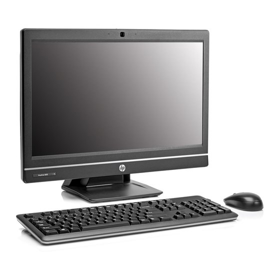
Product features Overview Figure 1-1 HP ProOne 600 G1 All-in-One The HP ProOne 600 G1 All-in-One offers the following features: Integrated All-in-One form factor ● Full HD IPS, LCD display (1920 x 1080) with LED backlighting ● 54.6-cm (21.5-inch) diagonal ◦... - Page 8 Optional Tray-load HP SuperMulti DVD+/-RW SATA Optical Disc Drive, DVD-ROM Disc Drive, or ● Slim BDXL Blu-ray Writer Intel Q85 Express chipset ● Two SODIMM slots with up to 16 GB of DDR3 SDRAM memory and dual channel memory support ●...
-
Page 9: Front Components
Front components Figure 1-2 Front components Table 1-1 Front components Component Component Webcam (optional) with privacy shutter Mute speaker Dual microphone array (optional) Reduce volume Webcam activity LED (with optional webcam) Increase volume 16:9 widescreen LED-backlit LCD display Mute microphone Power LED Decrease brightness High-performance stereo speakers... -
Page 10: Side Components
Side components Figure 1-3 Side components Table 1-2 Side components Component Component Hard disc drive activity LED Headset/line out jack HP 6-in-1 media card reader (optional) Tray-load optical disc drive USB 3.0 port, fast-charging Optical disc drive eject button USB 3.0 port Optical disc drive activity LED Microphone/line in jack Power button... -
Page 11: Rear Components
Rear components Figure 1-4 Rear components Table 1-3 Rear components Component Component Access panel RJ-45 Gigabit Ethernet port Access panel latches (2) USB 3.0 ports Security lock slot DisplayPort connector Power connector Stereo audio line out (2) PS/2 mouse and keyboard connectors Access panel security screw (2) USB 2.0 ports Serial port (optional) -
Page 12: Keyboard Features
Keyboard features Figure 1-5 Keyboard features Table 1-4 Keyboard features Component Component Sleep Mute Volume Fast Reverse Decrease Volume Play/Pause Increase Volume Stop Function Fast Forward Chapter 1 Product features... -
Page 13: Positioning The Computer
Positioning the computer This computer may be shipped with no stand, with a height-adjustable stand, or a tilt/swivel stand. The computer may be placed in the landscape position with the HP logo on the bottom bezel or it may be placed in the portrait position with the HP logo on the right side, as you face the computer. -
Page 14: Adjusting The Tilt/Swivel Stand (Optional)
WARNING! If the height-adjustable/recline stand is installed, before laying the computer down for service, first grasp the sides of the display and raise the display to the highest position. Do not lay the computer down with the sliding stand in the low position. The stand may suddenly release, which could cause injury or damage to equipment. - Page 15 Figure 1-10 Adjusting swivel Positioning the computer...
-
Page 16: Hardware Repair And Upgrade
Hardware repair and upgrade Warnings and cautions Before performing upgrades be sure to carefully read all of the applicable instructions, cautions, and warnings in this guide. WARNING! To reduce the risk of personal injury from electrical shock, hot surfaces, or fire: Disconnect the power cord from the wall outlet and allow the internal system components to cool before touching. -
Page 17: Additional Information
CAUTION: Static electricity can damage the electrical components of the computer or optional equipment. Before beginning these procedures, be sure that you are discharged of static electricity by briefly touching a grounded metal object. See Electrostatic discharge on page 49 for more information. -
Page 18: Disconnecting Power
If the tilt/swivel stand is installed on the computer, attach the cable management cover: Position the cable management cover under the cables and align the cover hooks with the slots in the stand. insert the cover hooks into the stand and slide the cover down to secure it. Figure 2-2 Installing the cable management cover Replace the rear port cover. -
Page 19: Installing And Removing The Rear Port Cover
Installing and removing the rear port cover Installing the rear port cover Be sure that all cables are connected. Place the cover against the computer, lining up the cable lock slot in the cover about 12 mm (0.5 inch) below the cable lock slot in the computer. Slide the cover up and into position. Figure 2-3 Installing the rear port cover Removing the rear port cover... -
Page 20: Installing A Security Lock
Installing a security lock The optional security lock enables you to secure your computer. A cable lock is a key lock device that has a wire cable attached. You attach one end of the cable to your desk (or other stationary object) and the other end of the cable to the cable lock slot on the computer. -
Page 21: Synchronizing The Optional Wireless Keyboard And Mouse
Synchronizing the optional wireless keyboard and mouse The optional wireless keyboard and mouse are easy to set up. Just remove the battery tabs on both the keyboard and the mouse to activate the preinstalled batteries. Also, make sure the Power switch on the bottom of the mouse is in the On position (the keyboard does not have a Power switch). -
Page 22: Removing Batteries From The Optional Wireless Keyboard Or Mouse
Removing batteries from the optional wireless keyboard or mouse NOTE: The wireless keyboard and mouse are optional components. To remove batteries from the wireless keyboard, remove the battery door on the underside of the keyboard (1) and lift the batteries out of the battery compartment (2). Figure 2-8 Removing batteries from the wireless keyboard To remove batteries from the wireless mouse, remove the battery door on the underside of the mouse... -
Page 23: Attaching The Computer To A Mounting Fixture
Attaching the computer to a mounting fixture You can remove the computer from the stand and install it on a wall, monitor arm, or other mounting fixture. There is a VESA mount under the computer stand that is used for mounting the computer. Table 2-1 Computer dimensions (without stand) Computer dimensions (without stand) -
Page 24: Installing And Removing A Stand
Installing and removing a stand Two stands are available for the computer: Height-adjustable/recline stand ● Tilt/swivel stand ● Installing and removing a height-adjustable/recline stand (optional) Installing a height-adjustable/recline stand To install the stand: Place the computer face down on a soft flat surface. HP recommends that you set down a blanket, towel, or other soft cloth to protect the bezel and screen surface from scratches or other damage. -
Page 25: Removing A Height-Adjustable/Recline Stand
Tighten the four captive screws to secure the stand to the chassis. Figure 2-12 Securing the stand Removing a height-adjustable/recline stand To remove the stand: Remove all removable media, such as compact discs or USB flash drives, from the computer. Turn off the computer properly through the operating system, then turn off any external devices. - Page 26 Place the computer face down on a soft flat surface. HP recommends that you set down a blanket, towel, or other soft cloth to protect the bezel and screen surface from scratches or other damage. WARNING! Before laying the computer down for service, first grasp the sides of the display and raise the display to the highest position.
-
Page 27: Installing And Removing A Tilt/Swivel Stand (Optional)
Lift the stand up and off the computer. Figure 2-15 Removing the stand Installing and removing a tilt/swivel stand (optional) Installing a tilt/swivel stand To install the stand: Place the computer face down on a soft flat surface. HP recommends that you set down a blanket, towel, or other soft cloth to protect the bezel and screen surface from scratches or other damage. -
Page 28: Removing A Tilt/Swivel Stand
Tighten the captive screws to secure the stand to the chassis. Figure 2-17 Securing the stand Align the top of the back of the stand with the stand, and press it into place, working along the sides until it is in place. Figure 2-18 Installing the back of the stand Removing a tilt/swivel stand... - Page 29 Remove/disengage any security devices that prohibit opening the computer. Place the computer face down on a soft flat surface. HP recommends that you set down a blanket, towel, or other soft cloth to protect the bezel and screen surface from scratches or other damage. Push the release button (1) on the bottom of the stand and pull the back of the stand off (2) the computer.
-
Page 30: Connecting A Second Display
Lift the stand up and off the computer. Figure 2-21 Removing the stand Connecting a second display The DisplayPort connector on the rear of the computer allows you to connect a second display to the computer. If you are adding a second display that has a DisplayPort connector, then no DisplayPort video adapter is required. - Page 31 If your second display has a DisplayPort connector, connect a DisplayPort cable directly between the DisplayPort connector on the rear of the computer and the DisplayPort connector on the second display. Figure 2-22 Connecting a DisplayPort cable Figure 2-23 Connecting a second display Connecting a second display...
- Page 32 If your second display does not have a DisplayPort connector, connect a DisplayPort video adapter to the DisplayPort connector of the computer. Then connect a cable (VGA, DVI. or HDMI, depending on your application) between the adapter and a second display. NOTE: When a DisplayPort adaptor is used, the rear port cover cannot be installed unless a DisplayPort extender cable is used in conjunction with the adaptor.
-
Page 33: Locating Internal Components
Locating internal components The following sections contain procedures for removing and replacing these internal components: Memory ● Battery ● Hard disc drive, solid state drive, or self-encrypting drive ● Optical disc drive ● Figure 2-25 Locating internal components Component Component Optical disc drive Memory Hard disc drive... -
Page 34: Removing And Installing Memory
Removing and installing memory The computer comes with double data rate 3 synchronous dynamic random access memory (DDR3- SDRAM) small outline dual inline memory modules (SODIMMs). SODIMMs The memory sockets on the system board can be populated with up to two industry-standard SODIMMs. -
Page 35: Populating Sodimm Sockets
Populating SODIMM sockets The system will automatically operate in single channel mode, dual channel mode, or flex mode, depending on how the SODIMMs are installed. Refer to the following table to identify the SODIMM channel locations. Table 2-2 Identifying SODIMM locations Location System board label Channel... - Page 36 Slide the access panel latches toward the edges of the unit, then slide the access panel toward the top of the computer until it slides off the unit. Figure 2-26 Removing the access panel To remove a memory module, press outward on the two latches on each side of the SODIMM (1), then pull the SODIMM out of the socket (2).
- Page 37 To install a memory module, slide the SODIMM into the socket at approximately a 30° angle (1), then press the SODIMM down (2) so that the latches lock it in place. Figure 2-28 Installing a memory module NOTE: A memory module can be installed in only one way. Match the notch on the module with the tab on the memory socket.
-
Page 38: Replacing The Battery
Replacing the battery The battery is located on the system board on the lower right side of the fan. The battery that comes with the computer provides power to the real-time clock. When replacing the battery, use a battery equivalent to the battery originally installed in the computer. The computer comes with a 3-volt lithium coin cell battery. - Page 39 Slide the access panel latches toward the edges of the chassis, then slide the access panel toward the top of the computer until it slides off the chassis. Figure 2-30 Removing the access panel The battery can now be seen on the lower right side of the fan. Figure 2-31 Locating the battery To release the battery from its holder, squeeze the metal clamp that extends above one edge of...
- Page 40 To insert the new battery, slide one edge of the replacement battery under the holder’s lip with the positive side up. Push the other edge down until the clamp snaps over the other edge of the battery (2). Figure 2-32 Removing and replacing a coin cell battery To replace the access panel, set the panel on the back of the computer, slightly above the stand, and slide it down into place.
-
Page 41: Replacing Drives
Replacing drives Replacing a hard disc drive The hard disc drive is located behind the access panel on the lower left side of the computer (when viewed from behind). The drive is housed in a removable cage. Any one of the following may be installed in the computer: One 3.5-inch hard disc drive ●... - Page 42 Slide the access panel latches toward the edges of the chassis, then slide the access panel toward the top of the computer until it slides off the chassis. Figure 2-34 Removing the access panel Pull the latch next to the lower side of the drive cage away from the cage to release it, then slide the cage toward the edge of the chassis and lift it out.
-
Page 43: Removing A 2.5-Inch Hard Disc Drive
Lift the latch on one side of the drive cage and pull the hard disc drive out of the cage. Figure 2-36 Removing the 3.5-inch hard disc drive from the cage Remove the four mounting screws from the 3.5-inch hard disc drive. Be sure to keep the screws together with the blue rubber grommets to use to install a replacement disc drive. - Page 44 Place the computer face down on a soft flat surface. HP recommends that you set down a blanket, towel, or other soft cloth to protect the bezel and screen surface from scratches or other damage. Slide the access panel latches toward the edges of the chassis, then slide the access panel toward the top of the computer until it slides off the chassis.
- Page 45 Slide the drive adapter holding the 2.5-inch drive or drives out of the drive cage. Figure 2-40 Removing the 2.5-inch drive adapter from the drive cage Remove the four mounting screws from the 2.5-inch hard disc drive adapter. Be sure to keep the screws together with the blue rubber grommets to use to install a replacement drive.
-
Page 46: Installing A Hard Disc Drive
Installing a hard disc drive Installing a 3.5-inch hard disc drive ● Installing 2.5-inch hard disc drives ● Installing a 3.5-inch hard disc drive Screw the four mounting screws into the 3.5-inch hard disc drive. Be sure to keep the blue rubber grommets behind each screw. - Page 47 With the 3.5-inch hard disc drive connector facing toward the center of the chassis, place the hard disc drive cage into the chassis and slide it toward the center until it snaps into place. Figure 2-44 Installing the 3.5-inch hard disc drive cage To replace the access panel, set the panel on the back of the computer, slightly above the stand, and slide it down into place.
-
Page 48: Installing 2.5-Inch Hard Disc Drives
Installing 2.5-inch hard disc drives Insert the 2.5-inch hard disc drive or drives into the 2.5-inch disc drive adapter. Be sure that the connectors are at the opening of the adapter. NOTE: The primary drive is the lower position in the drive adapter. If only one drive is to be installed, it must occupy this position. - Page 49 Slide the drive adapter holding the 2.5-inch drive or drives into the drive cage. Figure 2-47 inserting the 2.5-inch drive adapter into the drive cage Replacing drives...
- Page 50 Position the drive cage above its final site with the hard disc drive connectors facing toward the center of the chassis. If the drive cage contains a secondary (upper) drive, connect the SATA cable to the right of the drive cage to the secondary drive. Figure 2-48 Connecting the secondary 2.5-drive Place the drive cage into the chassis and slide it toward the center until it snaps into place.
-
Page 51: Replacing The Optical Disc Drive
To replace the access panel, set the panel on the back of the computer, slightly above the stand, and slide it down into place. Figure 2-50 Replacing the access panel Reconnect the power cord and external devices. Lock any security devices that were disengaged when the access panel was removed. Place the computer in the upright position. - Page 52 Slide the access panel latches toward the edges of the chassis, then slide the access panel toward the top of the computer until it slides off the chassis. Figure 2-51 Removing the access panel Lift the tab at the back of the optical disc drive enclosure to release the drive. Figure 2-52 Removing the optical disc drive Chapter 2 Hardware repair and upgrade...
- Page 53 Remove the two screws securing the optical disc drive bracket to the drive. Figure 2-53 Removing the optical disc drive bracket Secure the optical disc drive bracket to the new drive with the two screws. Figure 2-54 Attaching the optical disc drive bracket Replacing drives...
- Page 54 Align the new optical disc drive with the opening in the side of the computer. Push the drive in firmly until it snaps into place. NOTE: The optical disc drive can be installed in only one way. Figure 2-55 Installing the optical disc drive To replace the access panel, set the panel on the back of the computer, slightly above the stand, and slide it down into place.
-
Page 55: Appendix A Electrostatic Discharge
Electrostatic discharge A discharge of static electricity from a finger or other conductor may damage system boards or other static-sensitive devices. This type of damage may reduce the life expectancy of the device. Preventing electrostatic damage To prevent electrostatic damage, observe the following precautions: Avoid hand contact by transporting and storing products in static-safe containers. -
Page 56: Appendix B Computer Operating Guidelines, Routine Care, And Shipping Preparation
Computer operating guidelines, routine care, and shipping preparation Computer operating guidelines and routine care Follow these guidelines to properly set up and care for the computer: Keep the computer away from excessive moisture, direct sunlight, and extremes of heat and cold. ●... -
Page 57: Optical Disc Drive Precautions
Wipe the screen with a soft, clean antistatic cloth. For more difficult cleaning situations, use a ◦ 50/50 mix of water and Isopropyl alcohol. Spray the cleaner onto a cloth and use the damp cloth to gently wipe the screen surface. Never spray the cleaner directly on the screen surface. -
Page 58: Index
Index additional information 11 hard disc drive memory 2.5-inch 35 installing 29 2.5-inch, installing 42 removing 29 battery replacement 32 2.5-inch, removing 37 SODIMMs specifications 28 3.5-inch 35 specifications 28 3.5-inch, installing 40 mounting the computer 17 components 3.5-inch, removing 35 mouse front 3 replacing 35... - Page 59 security access panel security screw location 14 cable lock slot location 14 shipping preparation 51 side components 4 SODIMM identification 29 location 29 specifications 28 specifications, memory 28 stand height-adjustable/recline, installing 18 height-adjustable/recline, removing 19 tilt/swivel stand, installing 21 tilt/swivel stand, removing 22 swivel adjustment 8 synchronizing wireless keyboard and mouse 15...