Table of Contents
Advertisement
Advertisement
Table of Contents

Related Manuals for Asus Z87-A


Summary of Contents for Asus Z87-A
- Page 1 Z87-A...
- Page 2 Product warranty or service will not be extended if: (1) the product is repaired, modified or altered, unless such repair, modification of alteration is authorized in writing by ASUS; or (2) the serial number of the product is defaced or missing.
-
Page 3: Table Of Contents
Contents Safety information ...................... iv About this guide ......................iv Z87-A specifications summary ................. vi Chapter 1: Product introduction Before you proceed ................... 1-1 Motherboard overview ................1-2 Central Processing Unit (CPU) ..............1-4 System memory ..................1-8 Expansion slots..................1-22 Onboard buttons .................. -
Page 4: Safety Information
Safety information Electrical safety • To prevent electrical shock hazard, disconnect the power cable from the electrical outlet before relocating the system. • When adding or removing devices to or from the system, ensure that the power cables for the devices are unplugged before the signal cables are connected. If possible, disconnect all power cables from the existing system before you add a device. -
Page 5: Conventions Used In This Guide
Refer to the following sources for additional information and for product and software updates. ASUS websites The ASUS website provides updated information on ASUS hardware and software products. Refer to the ASUS contact information. Optional documentation Your product package may include optional documentation, such as warranty flyers, that may have been added by your dealer. -
Page 6: Z87-A Specifications Summary
Z87-A specifications summary LGA1150 socket for the 4th Generation Intel Core™ i7/Intel Core™i5/ ® ® Intel Core™ i3, Pentium and Celeron processors ® ® ® Supports 22nm CPU Supports Intel Turbo Boost Technology 2.0* ® * The Intel Turbo Boost Technology 2.0 support depends on the CPU types. - Page 7 - ASUS EZ Flash 2 ASUS Q-Design - ASUS Q-LED (CPU, DRAM, VGA, Boot Device LED) - ASUS Q-Slot - ASUS Q-DIMM - ASUS Q-Connector* * The 1 x 2-in-1 ASUS Q-Connector kit is for retailer version only. (continues on the next page)
- Page 8 SFS (Stepless Frequency Selection) � BCLK/PCI� frequency tuning from 8���z up to �����z at �.1��z increment Overclocking Protection - ASUS C.P.R. (CPU Parameter Recall) Rear Panel I/O Ports 1 x PS/2 Keyboard/mouse combo port 1 x Mini DisplayPort 1 x HDMI port...
- Page 9 1 x ASUS SLI bridge connector* ASUS I/O shield 2 in 1 Q-connector** User’s manual * (Optional) SLI bridge connector is only available for the standard Z87-A edition. ** The 1 x 2-in-1 ASUS Q-Connector kit is for retailer version only. Support DVD Drivers...
-
Page 11: Chapter 1: Product Introduction
Chapter 1 Product introduction Chapter 1: Product introduction Thank you for buying an ASUS Z87-A motherboard! ® Before you start installing the motherboard, and hardware devices on it, check the items in your motherboard package. Refer to the specification list on page ix for the list of accessories. -
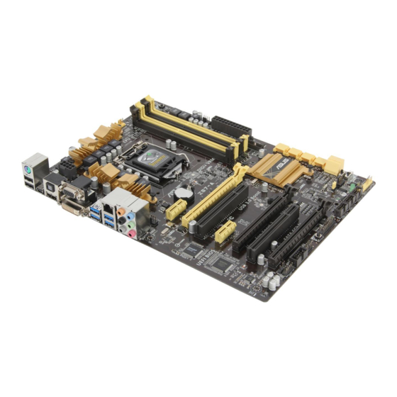
Page 12: Motherboard Overview
Screw holes Place eight screws into the holes indicated by circles to secure the motherboard to the chassis. Do not overtighten the screws! Doing so can damage the motherboard. Place this side towards the rear of the chassis ASUS Z87-A... -
Page 13: Motherboard Layout
1.2.3 Motherboard layout Chapter 1: Product introduction... -
Page 14: Central Processing Unit (Cpu)
The motherboard comes with a surface mount LGA1150 socket designed for the 4th generation Intel Core™ i7 / Intel Core™ i5 / Intel Core™ i3, Pentium and Celeron ® ® ® ® ® processors. . Ensure that all power cables are unplugged before installing the CPU. ASUS Z87-A... -
Page 15: Installing The Cpu
Contact your retailer immediately if the PnP cap is missing, or if you see any damage to the PnP cap/socket contacts/motherboard components. ASUS will shoulder the cost of repair only if the damage is shipment/ transit-related. - Page 16 Apply the Thermal Interface Material to the CPU heatsink and CPU before you install the heatsink and fan, if necessary. ASUS Z87-A...
-
Page 17: Installing The Cpu Heatsink And Fan
1.3.2 Installing the CPU heatsink and fan To install the CPU heatsink and fan assembly To uninstall the CPU heatsink and fan assembly Chapter 1: Product introduction... -
Page 18: System Memory
A DDR3 module is notched differently from a DDR or DDR2 module. DO NOT install a DDR or DDR2 memory module to the DDR3 slot. Recommended memory configurations Install one memory module in slot A2 first as a single�channel operation. ASUS Z87-A... -
Page 19: Memory Configurations
1.4.2 Memory configurations You may install 2GB, 4GB and 8GB unbuffered and non-ECC DDR3 DIMMs into the DIMM sockets. • You may install varying memory sizes in Channel A and Channel B. The system maps the total size of the lower�sized channel for the dual�channel configuration. Any excess memory from the higher�sized channel is then mapped for single�channel operation. - Page 20 Z87-A Motherboard Qualified Vendors Lists (QVL) DDR3 2800(O.C.) MHz capability Vendors Part No. Size Chip Chip Timing Voltage DIMM socket Brand support (Optional) G.SKILL F3-2800C11Q-16GTXD(XMP) 16GB (4x4GB) 11-13-13-35 1.65 • • • G.SKILL F3-2800C12Q-32GTXD(XMP) 32GB (4x8GB) 12-13-13-35 1.65 • •...
- Page 21 DDR3 2400(O.C.) MHz capability Vendors Part No. Size Chip Chip Timing Voltage DIMM socket Brand support (Optional) A-DATA AX3U2400GC4G10(XMP) 10-12-12-31 1.65 • • • Apacer 78.BAGFL.AFD0C(XMP) 8GB (2x4GB) 11-12-12-30 • • • Apacer 783BAGF3.AFD0C(XMP) 8GB (2x4GB) 11-11-11-30 • • • CORSAIR CMGTX8(XMP) 8GB (4x2GB)
- Page 22 • Patriot PXD38G2133C1 1K(XMP) 8GB (2x4GB) 9-9-9-24 1.65 • • • Patriot PXD38G2133C11 K(XMP) 8GB (2x4GB) 2133 11-11-11-27 • • • Team TLD38G2133HC11A BK(XMP) 11-11-11-31 1.65 • • • Team TXD34096M2133HC11A- 11-11-11-31 1.65 • • • V(XMP) ASUS Z87-A 1-12...
- Page 23 DDR3 2000(O.C.) MHz capability Vendors Part No. Size Chip Chip NO. Timing Voltage DIMM socket Brand support (Optional) AEXEA AXA3ES2G2000LG28V(XMP) 1.65 • • • AEXEA AXA3ES4GK2000LG28V(XMP) 4GB (2x2GB) 1.65 • • • Apacer 78.AAGD5.9KD(XMP) 6GB (3x2GB) 9-9-9-27 • • • Asint SLA302G08-ML2HB(XMP) Hynix...
- Page 24 • • AE34G1609U2-U 23EY4587MB6H • • • AP38G1608U 8GB (2x4GB) 9-9-9-28 1.65 • • • 2K(XMP) Apacer 78.B1GE3.9L10C Apacer AM5D5908DEQSCK 1.65 • • • Apacer 78.B1GET.9K00C Apacer AM5D6008BQQSCK 11-11-11-28 • • • (continued on the next page) ASUS Z87-A 1-14...
- Page 25 DDR3 1600 MHz capability Vendors Part No. Size Chip Chip NO. Timing Voltage DIMM socket Brand support (Optional) Apacer 78.C1GET.9K10C Apacer AM5D6008 11-11- • • • BQQSCK 11-31 Apacer AHU04GFA60C9Q1D(XMP) 9-9-9-27 1.65 • • • Apacer AHU04GFA60C9Q3R(XMP) 11-11- • • •...
- Page 26 8GB (2x4GB) 9-9-9-24 1.35 • • • 8GX(XMP) KINGSTON KHX1600C9D3P1K2/ 8GB (2x4GB) • • • KINGSTON KHX1600C9D3T 12GB (3x4GB) 1.65 • • 1BK3/12GX(XMP) KINGSTON KHX1600C9D3T1K3/ 6GB (3x2GB) 1.65 • • • 6GX(XMP) (continued on the next page) ASUS Z87-A 1-16...
- Page 27 DDR3 1600 MHz capability Vendors Part No. Size Chip Chip NO. Timing Voltage DIMM socket Brand support (Optional) KINGSTON KHX16C10B1K2/ 16GB • • • 16X(XMP) (2x8GB) KINGSTON KHX16C9K2/16 16GB 1333-9- • • (2x8GB) 9-9-24 KINGSTON KHX16C9P1K2/16 16GB • • • (2x8GB) KINGSTON KVR16N11/4...
- Page 28 3C9A EK Memory EKM324L28B 4GB (2x2GB) • • • P8-I13 G.SKILL 4GB (2x2GB) G.SKILL D3 128M8CE9 2GB 9-9-9-24 • • • 10600CL9D- 4GBNT G.SKILL 8GB (2x4GB) 9-9-9-24 • • • 10666CL9D- 8GBRL (continued on the next page) ASUS Z87-A 1-18...
- Page 29 DDR3 1333 MHz capability Vendors Part No. Size Chip Brand Chip NO. Timing Voltage DIMM socket support (Optional) G.SKILL F3-10666CL9D- 8GB (2x4GB) 9-9-9-24 • • • 8GBRL G.SKILL F3-10666CL9D- 8GB (2x4GB) 9-9-9-24 • • • 8GBXL GEIL GB34GB1333C7DC 4GB (2x2GB) GEIL GL1L128M8 7-7-7-24...
- Page 30 • Power 33V02 Silicon SP004GBLTU1 S-POWER 20YT3NG 9-9-9-24 • • • Power 33V02 Team TED34096M1 Team T3D2568LT-13 • • • 333HC9 Transcend JM1333KLH-8 Transcend TK963EBF3 • • • G(623654) Transcend TS1GLK64V3 MICRON D9QBJ • • • H(620053) ASUS Z87-A 1-20...
-
Page 31: Dimm Installation
Hyper DIMM support is subject to the physical characteristics of individual CPUs. Load the X.M.P. or D.O.C.P. settings in the BIOS for the hyper DIMM support. • Visit the ASUS website for the latest QVL. 2.3.4 DIMM installation Chapter 1: Product introduction... -
Page 32: Expansion Slots
Remove the bracket opposite the slot that you intend to use. Keep the screw for later use. Align the card connector with the slot and press firmly until the card is completely seated on the slot. Secure the card to the chassis with the screw you removed earlier. Replace the system cover. ASUS Z87-A 1-22... -
Page 33: Configuring An Expansion Card
1.5.2 Configuring an expansion card After installing the expansion card, configure it by adjusting the software settings. Turn on the system and change the necessary BIOS settings, if any. See Chapter 2 for information on BIOS setup. Assign an IRQ to the card. Install the software drivers for the expansion card. -
Page 34: Onboard Buttons
Installing DIMMs that are not compatible with the motherboard may cause system boot failure, and the DRAM_LED near the MemOK! switch lights continuously. Press and hold the MemOK! button until the DRAM_LED starts blinking to begin automatic memory compatibility tuning for successful boot. ASUS Z87-A 1-24... - Page 35 • We recommend that you download and update to the latest BIOS version from the ASUS website at www.asus.com after using the MemOK! function. DirectKey button This feature allows your system to go to the BIOS Setup program with the press of a button.
- Page 36 You may use the 4�Way Optimization and TPU feature in the AI Suite � application, adjust the BIOS setup program or enable the TPU switch at the same time. However, the system will use the last setting you have made. ASUS Z87-A 1-26...
-
Page 37: Onboard Leds
EPU switch Enable this switch to automatically detect the current PC loadings and intelligently moderate the power consumption. Enable this switch when the system is powered off. • The EPU LED (OLED2) near the EPU switch lights up when the EPU switch is enabled. - Page 38 The POST State LEDs provide the status of these key components during POST (Power-On-Self Test): CPU, memory modules, VGA card, and hard disk drives. If an error is found, the critical component’s LED stays lit up until the problem is solved. ASUS Z87-A 1-28...
-
Page 39: Jumpers
Jumpers Clear RTC RAM (3-pin CLRTC) This jumper allows you to clear the Real Time Clock (RTC) RAM in CMOS. You can clear the CMOS memory of date, time, and system setup parameters by erasing the CMOS RTC RAM data. The onboard button cell battery powers the RAM data in CMOS, which include system setup information such as system passwords. -
Page 40: Connectors
Due to the design of the Intel 8 series chipset, all USB devices connected to the ® USB 2.0 and USB 3.0 ports are controlled by the xHCI controller. Some legacy USB devices must update their firmware for better compatibility. ASUS Z87-A 1-30... -
Page 41: Lan Port Led Indications
• Multi-VGA output supports up to three displays under Windows OS environment, two ® displays under BIOS, and one display under DOS. • Intel display architecture design supports the following maximum supported pixel clocks (Pixel Clock = H total x V Total x Frame Rate (Screen refresh rate)): �... -
Page 42: Internal Connectors
If you want to use two or more high-end PCI Express x16 cards, use a PSU with 1000W power or above to ensure the system stability. • If you are uncertain about the minimum power supply requirement for your system, refer to the Recommended Power Supply Wattage Calculator at http://support.asus. com/PowerSupplyCalculator/PSCalculator.aspx?SLanguage=en-us for details. ASUS Z87-A 1-32... - Page 43 Intel Intel Z87 Serial ATA 6.0 Gb/s connectors (7-pin SATA6G_1-6 [yellow]) ® These connectors connect to Serial ATA 6.0 Gb/s hard disk drives via Serial ATA 6.0 Gb/s signal cables. If you installed Serial ATA hard disk drives, you can create a RAID 0, 1, 5, and 10 configuration with the Intel Rapid Storage Technology through the onboard Intel ®...
- Page 44 Ensure that the CPU fan is securely installed to the CPU fan connector. • The CPU_FAN connector supports the CPU fan of maximum 1A (12 W) fan power. • The CPU_FAN connector and CHA_FAN connectors support the ASUS FAN Xpert 2 feature. ASUS Z87-A 1-34...
- Page 45 USB 3.0 connector (20-1 pin USB3_12) USB 3.0 connector (20-1 pin USB3_12) This connector allows you to connect a USB 3.0 module for additional USB 3.0 front or rear panel ports. With an installed USB �.� module, you can enjoy all the benefits of USB 3.0 including faster data transfer speeds of up to 5Gbps, faster charging time for USB�chargeable devices, optimized power efficiency, and backward compatibility with USB 2.0.
- Page 46 Never connect a 1394 cable to the USB connectors. Doing so will damage the motherboard! You can connect the front panel USB cable to the ASUS Q�Connector (USB, blue) first, and then install the Q-Connector (USB) to the USB connector onboard if your chassis supports front panel USB ports.
- Page 47 Serial port connectors (10-1 pin COM) The connector is for a serial (COM) port. Connect the serial port module cable to the connector, then install the module to a slot opening at the back of the system chassis. The serial port bracket (COM) is purchased separately. Digital audio connector (4-1 pin SPDIF_OUT) This connector is for an additional Sony/Philips Digital Interface (S/PDIF) port.
- Page 48 Connect the button cable that supports DirectKey, from the chassis to this connector on the motherboard. Ensure that your chassis comes with the extra button cable that supports the DirectKey feature. Refer to the technical documentation that came with the chassis for details. ASUS Z87-A 1-38...
-
Page 49: System Panel Connector
Pressing the power switch for more than four seconds while the system is ON turns the system OFF. • Reset button (2-pin RESET) This 2-pin connector is for the chassis-mounted reset button for system reboot without turning off the system power. To install ASUS Q-Connector Chapter 1: Product introduction 1-39... -
Page 50: Software Support
The contents of the support DVD are subject to change at any time without notice. Visit the ASUS website at www.asus.com for updates. Running Support DVD Place the support DVD into the optical drive. The DVD automatically displays the Drivers menu if Autorun is enabled in your computer. -
Page 51: Chapter 2: Bios Information
Inappropriate BIOS updating may result in the system’s failure to boot. Carefully follow the instructions of this chapter to update your BIOS if necessary. Visit the ASUS website at www.asus.com to download the latest BIOS file for this motherboard. The following utilities allow you to manage and update the motherboard BIOS setup program. -
Page 52: Asus Ez Flash
2.1.2 ASUS EZ Flash 2 The ASUS EZ Flash 2 feature allows you to update the BIOS without using an OS-based utility or a bootable floppy disk. Before you start using this utility, download the latest BIOS file from the ASUS website at www.asus.com. -
Page 53: Asus Crashfree Bios 3 Utility
2.1.3 ASUS CrashFree BIOS 3 utility The ASUS CrashFree BIOS � is an auto recovery tool that allows you to restore the BIOS file when it fails or gets corrupted during the updating process. You can restore a corrupted BIOS file using the motherboard support DVD or a USB flash drive that contains the updated BIOS file. -
Page 54: Asus Bios Updater
2.1.4 ASUS BIOS Updater The ASUS BIOS Updater allows you to update BIOS in DOS environment. This utility also allows you to copy the current BIOS file that you can use as a backup when the BIOS fails or gets corrupted during the updating process. -
Page 55: Updating The Bios File
At the FreeDOS prompt, type bupdater /pc /g and press <Enter>. D:\>bupdater /pc /g The BIOS Updater screen appears as below. ASUSTek BIOS Updater for DOS V1.30 [2013/02/22] FLASH TYPE: MX1C 25L1065A Current ROM Update ROM BOARD: Z87-A BOARD: UNKNOWN VER: 0204 VER: UNKNOWN DATE: 01/01/2013... -
Page 56: Bios Setup Program
The BIOS setup program does not support the bluetooth devices. BIOS menu screen The BIOS Setup program can be used under two modes: EZ Mode and Advanced Mode. You can change modes from the Exit menu or from the Exit/Advanced Mode screen. ASUS Z87-A... - Page 57 2.2.1 EZ Mode By default, the EZ Mode screen appears when you enter the BIOS setup program. The EZ Mode provides you an overview of the basic system information, and allows you to select the display language, system performance mode and boot device priority. To access the Advanced Mode, click Exit/Advanced Mode, then select Advanced Mode or press F7 hot key for the advanced BIOS settings.
-
Page 58: Advanced Mode
For changing the advanced system settings For displaying the system temperature, power status, and changing the Monitor fan settings. Boot For changing the system boot configuration Tool For configuring options for special functions Exit For selecting the exit options and loading default settings ASUS Z87-A... -
Page 59: Menu Items
Menu items The highlighted item on the menu bar displays the specific items for that menu. For example, selecting Main shows the Main menu items. The other items (Ai Tweaker, Advanced, Monitor, Boot, Tool, and Exit) on the menu bar have their respective menu items. -
Page 60: My Favorites
Favorites page. You cannot add the following items to My Favorite page: • Items with submenu options • User-managed items such as language and boot order • Configuration items such as �emory SPD Information, system time and date. ASUS Z87-A 2-10... -
Page 61: Main Menu
Main menu The Main menu screen appears when you enter the Advanced Mode of the BIOS Setup program. The Main menu provides you an overview of the basic system information, and allows you to set the system date, time, language, and security settings. 2.4.1 System Language [English] Allows you to choose the BIOS language version from the options. -
Page 62: Administrator Password
To clear the user password, follow the same steps as in changing a user password, but press <�nter> when prompted to create/confirm the password. After you clear the password, the User Password item on top of the screen shows Not Installed. ASUS Z87-A 2-12... -
Page 63: Ai Tweaker Menu
Ai Tweaker menu The Ai Tweaker menu items allow you to configure overclocking�related items. Be cautious when changing the settings of the Ai Tweaker menu items. Incorrect field values can cause the system to malfunction. The configuration options for this section vary depending on the CPU and DI�� model you installed on the motherboard. - Page 64 Memory Profile Allows you to select the X.M.P. mode supported by your memory module. Configuration options: [Profile #1] [Profile #2] 2.5.2 ASUS MultiCore Enhancement [Enabled] Default set to [Enabled] for maximum performance under XMP/Manual/ [Enabled] User�defined memory frequency mode.
- Page 65 3-Core Ratio Limit [Auto] Select [Auto] to apply the CPU default Turbo Ratio setting or manually assign a 3-Core Limit value that must be higher than or equal to the 4-Core Ratio Limit. If you assign a value for 3-Core Ratio Limit, do not set the 1-Core Ratio Limit and 2-Core Ratio Limit to [Auto].
-
Page 66: Dram Timing Control
The following item appears only when you set the CPU Voltage Frequency to [Manual]. CPU Fixed Frequency [300] This item allows you to set a fixed CPU Voltage frequency. Use the <+> or <�> keys to adjust the value. The values range from ���k�z to 5��k�z with a 5�k�z interval. ASUS Z87-A 2-16... - Page 67 The following items appear only when you set the CPU Voltage Frequency to [Auto]. VRM Spread Spectrum [Disabled] Enable the VRM Spread Spectrum to enhance system stability. Configuration options: [Disabled] [�nabled] Active Frequency Mode [Disabled] Set this item to Enabled to help enhance the power saving condition while switching frequencies.
-
Page 68: Cpu Power Management
Allows you to increase or decrease the switching frequency of the internal regulator. Decrease to help consume less power or increase to help votlage stability. When this item is set to [+] or [-], the Frequency Tuning Offset appears and allows you to set its value. ASUS Z87-A 2-18... - Page 69 CPU Internal Power Fault Control Thermal Feedback [Auto] Allows your system to take precautionary actions to be taken by the CPU when the thermal conditions of the external regulator exceeds the threshold. Configuration options: [Auto] [Disabled] [�nabled] CPU Integrated VR Fault Management [Auto] Disable this item to prevent tripping the Fully Integrated Voltage Regulator when doing over-voltage.
- Page 70 To offset the voltage by a positive value. [–] To offset the voltage by a negative value. CPU Core Voltage Offset Use the <+> or <-> keys to adjust the value. The values range from 0.001V to 0.999V with a 0.001V interval. ASUS Z87-A 2-20...
- Page 71 2.5.17 CPU Cache Voltage [Auto] Allows you to configure the amount of voltage fed to the uncore of the processor including its cache. Increase the voltage when increasing Ring frequency. Configuration options: [Auto] [�anual �ode] [Offset �ode] [Adaptive �ode] [Adaptive Mode] The following item appears only when you set the CPU Cache Voltage to [Manual Mode].
- Page 72 By default, this item takes the standard value of the installed CPU. Increase the amount of voltage when increasing DRAM frequency. You can use the <+> or <-> keys to adjust the value. The values range from 0.001V to 0.999V with a 0.001V interval. ASUS Z87-A 2-22...
- Page 73 2.5.21 CPU Digital I/O Voltage Offset Mode Sign [+] To offset the voltage by a positive value. [–] To offset the voltage by a negative value. CPU Digital I/O Voltage Offset [Auto] Allows you to configure the amount of voltage fed to the digital portion of the I/O on the processor.
- Page 74 BCLK DN is equal to the falling edge of the BCLK DP. You can use the <+> or <-> keys to adjust the value. The values range from 0.1V to 1.9V with a 0.10625V interval. 2.5.33 CPU Spread Spectrum [Auto] [Auto] Automatic configuration. [Disabled] Enhances the BCLK overclocking ability. [Enabled] Sets to [Enabled] for EMI control. ASUS Z87-A 2-24...
-
Page 75: Advanced Menu
Advanced menu The Advanced menu items allow you to change the settings for the CPU and other system devices. Be cautious when changing the settings of the Advanced menu items. Incorrect field values can cause the system to malfunction. 2.6.1 CPU Configuration The items in this menu show the CPU-related information that the BIOS automatically detects. - Page 76 The system controls the CPU speed. Turbo Mode [Enabled] Allows you to automatically set the processor cores to run faster than the base frequency when operating below power, current and temperature specification limit. Configuration options: [�nabled] [Disabled] ASUS Z87-A 2-26...
-
Page 77: Pch Configuration
CPU C States [Auto] Allows you to enable or disable the CPU C states. Configuration options: [Auto] [�nabled] [Disabled] The following items appear only when you set the CPU C States to [Enabled]. Enhanced C1 state [Enabled] Allows your processor to reduce power when the system is in idle mode. Configuration options: [�nabled] [Disabled] CPU C3 Report [Enabled] Allows you to disable or enable the CPU C3 report to the operating system. -
Page 78: Intel Smart Connect Technology
Allows you to enable or disable the hybrid hard disk support. Configuration options: [�nabled] [Disabled] Intel Smart Connect Technology ISCT Support [Disabled] Allow you to enable or disable the Intel Smart Connect Technology. ® Configuration options: [�nabled] [Disabled] ASUS Z87-A 2-28... -
Page 79: Sata Configuration
2.6.3 SATA Configuration While entering Setup, the BIOS automatically detects the presence of SATA devices. The SATA Port items show Not Present if no SATA device is installed to the corresponding SATA port. SATA Mode Selection [AHCI] Allows you to set the SATA configuration. [Disabled] Disables the SATA function. -
Page 80: Graphics Configuration
Allows you to enable or disable the control of Active State Power Management on SA side of the DMI Link. Configuration options: [Auto] [Disabled] [L�s] [L1] [L�sL1] PEG - ASPM [Disabled] Allows you to control ASPM support for the PEG device. Configuration options: [Disabled] [Auto] [ASP� L�s] [ASP� L1] [ASP� L�sL1] ASUS Z87-A 2-30... -
Page 81: Memory Configuration
Memory Configuration Allows you to configure the memory configuration parameters. Memory Scrambler [Enabled] Allows you to enable or disable the Memory Scrambler support. Configuration options: [�nabled] [Disabled] Memory Remap [Enabled] Allows you to enable remapping the memory above 4GB. Configuration options: [�nabled] [Disabled] 2.6.5 USB Configuration The items in this menu allow you to change the USB-related features. -
Page 82: Platform Misc Configuration
® The following item appears only when you set the Realtek LAN Controller to [Enabled]. Realtek PXE OPROM [Disabled] Allows you to enable or disable the PXE OptionRom of the Realtek LAN controller. Configuration options: [�nabled] [Disabled] ASUS Z87-A 2-32... -
Page 83: Serial Port Configuration
Serial Port Configuration Allows you to set the parameters of the serial ports. This item only functions only if there is a serial port (COM1) connector connected to the motherboard. Serial Port [Enabled] Allows you to enable or disable the serial port. Configuration options: [Disabled] [�nabled] The following item appears only if you set the Serial Port to [Enabled]. -
Page 84: Monitor Menu
The Monitor menu displays the system temperature/power status, and allows you to change the fan settings. 2.7.1 CPU Temperature / MB Temperature [xxxºC/xxxºF] The onboard hardware monitor automatically detects and displays the CPU and motherboard temperatures. Select [Ignore] if you do not wish to display the detected temperatures. ASUS Z87-A 2-34... - Page 85 2.7.2 CPU Fan Speed [Ignore] or [Monitor] / [N/A], CPU OPT [Ignore] or [Monitor] / [N/A], CPU OPT or [Monitor] / [N/A], CPU OPT Speed [xxxx RPM] or [Ignore] / [N/A], Chassis Fan 1/3 Speed [xxxx RPM] or [Ignore] / [N/A] The onboard hardware monitor automatically detects and displays the CPU, chassis, and power fan speed in rotations per minute (RPM).
- Page 86 0% to 100%. When the chassis temperature is under 40ºC, the chassis fan will operate at the minimum duty cycle. 2.7.6 Anti Surge Support [Enabled] This item allows you to enable or disable the Anti Surge function. Configuration options: [Disabled] [�nabled] ASUS Z87-A 2-36...
-
Page 87: Boot Menu
Boot menu The Boot menu items allow you to change the system boot options. Boot Configuration 2.8.1 Fast Boot [Enabled] [Disabled] Allows your system to go back to its normal boot speed. [Enabled] Allows your system to accelerate the boot speed. The following items appear only when you set the Fast Boot to [Enabled]. - Page 88 Disables the full screen boot logo display during POST. The following items appear only when you set the Boot Logo Display to [Enabled]. Boot Logo Size Control [Auto] [Auto] Automatically adjusts for Windows requirements. ® [Full Screen] �aximizes the boot logo size. ASUS Z87-A 2-38...
- Page 89 Post Delay Time [3 sec] This item allows you to select a desired additional POST waiting time to easily enter the BIOS Setup. You can only execute the POST delay time during normal boot. The values range from 0 to 10 seconds. This feature will only work when set under normal boot.
-
Page 90: Secure Boot
[Other OS] Get the optimized function when booting on Windows non-UEFI ® mode, Windows Vista/ Windows XP, or other Microsoft Secure Boot ® ® ® non compliant OS. Microsoft Secure Boot only supports Windows ® ® UEFI mode. ASUS Z87-A 2-40... - Page 91 The following item appears only when you set the OS Type to [Windows UEFI mode]. Key Management This item appears only when you set OS Type to [Windows UEFI Mode]. It allows you to manage the Secure Boot keys. Install Default Secure Boot keys Allows you to immediately load the default Security Boot keys, Platform key (PK), Key-exchange Key (KEK), Signature database (db), and Revoked Signatures (dbx).
-
Page 92: Boot Option Priorities
• Press <F5> when ASUS Logo appears. Press <F5> when ASUS Logo appears. • Press <F8> after POST. Press <F8> after POST. • To select the boot device during system startup, press <F8> when ASUS Logo appears. ASUS Z87-A 2-42... -
Page 93: Tools Menu
2.9.1 ASUS EZ Flash 2 Utility Allows you to run ASUS �Z Flash 2. When you press <�nter>, a confirmation message appears. Use the left/right arrow key to select between [Yes] or [No], then press <Enter> to confirm your choice. -
Page 94: Asus Spd Information
We recommend that you update the BIOS file only coming from the same memory/ CPU configuration and BIOS version. 2.9.3 ASUS SPD Information Allows you to view the DRAM SPD information. DIMM Slot # [Slot 2] Displays the Serial Presence Detect (SPD) information of the DIMM module installed on the selected slot. -
Page 95: Exit Menu
<�sc>, a confirmation window appears. Select Yes to discard changes and exit. 2.10.4 ASUS EZ Mode This option allows you to enter the EZ Mode screen. 2.10.5 Launch EFI Shell from filesystem device This option allows you to attempt to launch the �FI Shell application (shellx64.efi) from one of... - Page 96 ASUS Z87-A 2-46...
-
Page 97: Appendices
Appendices Appendices Notices Federal Communications Commission Statement This device complies with Part 15 of the FCC Rules. Operation is subject to the following two conditions: • This device may not cause harmful interference. • This device must accept any interference received including interference that may cause undesired operation. -
Page 98: Canadian Department Of Communications Statement
ASUS Recycling/Takeback Services ASUS recycling and takeback programs come from our commitment to the highest standards for protecting our environment. We believe in providing solutions for you to be able to responsibly recycle our products, batteries, other components as well as the packaging materials. -
Page 99: Asus Contact Information
+1-812-282-3777 +1-510-608-4555 Web site usa.asus.com Technical Support Telephone +1-812-282-2787 Support fax +1-812-284-0883 Online support support.asus.com ASUS COMPUTER GmbH (Germany and Austria) Address Harkort Str. 21-23, D-40880 Ratingen, Germany +49-2102-959911 Web site www.asus.de Online contact www.asus.de/sales Technical Support Telephone +49-1805-010923* Support Fax... - Page 100 Z87-A...