Table of Contents
Advertisement
Quick Links
Intel® Desktop Board
DQ87PG
Technical Product Specification
May 2013
Part Number: G89983-001
The Intel Desktop Board DQ87PG may contain design defects or errors known as errata that may cause the product to deviate from published specifications.
Current characterized errata are documented in the Intel Desktop Board DQ87PG Specification Update.
Advertisement
Table of Contents

Related Manuals for Intel DQ87PG


Summary of Contents for Intel DQ87PG
- Page 1 Part Number: G89983-001 The Intel Desktop Board DQ87PG may contain design defects or errors known as errata that may cause the product to deviate from published specifications. Current characterized errata are documented in the Intel Desktop Board DQ87PG Specification Update.
-
Page 2: Revision History
“undefined.” Intel reserves these for future definition and shall have no responsibility whatsoever for conflicts or incompatibilities arising from future changes to them. Intel desktop boards may contain design defects or errors known as errata, which may cause the product to deviate from published specifications. Current characterized errata are available on request. - Page 3 Board Identification Information Basic Desktop Board DQ87PG Identification Information AA Revision BIOS Revision Notes G74154 PGQ8710H.86A Notes: The AA number is found on a small label on the component side of the board. The Q87 chipset used on this AA revision consists of the following component:...
- Page 4 Intel Desktop Board DQ87PG Technical Product Specification...
-
Page 5: Intended Audience
Intended Audience The TPS is intended to provide detailed, technical information about Intel Desktop Board DQ87PG and its components to the vendors, system integrators, and other engineers and technicians who need this level of information. It is specifically not intended for general audiences. - Page 6 Intel Desktop Board DQ87PG Technical Product Specification Other Common Notation Used after a signal name to identify an active-low signal (such as USBP0#) Gigabyte (1,073,741,824 bytes) GB/s Gigabytes per second Gb/s Gigabits per second Kilobyte (1024 bytes) Kilobit (1024 bits)
-
Page 7: Table Of Contents
1.10.3 Chassis Intrusion and Detection ..........30 1.10.4 Thermal Monitoring ............... 31 ® 1.10.5 Intel vPro™ Technology ............32 ® ® 1.11 Intel Management Engine (Intel ME) Software and Drivers ....37 1.12 Power Management ................39 1.12.1 ACPI ..................39 1.12.2 Hardware Support ..............41... - Page 8 Intel Desktop Board DQ87PG Technical Product Specification 2 Technical Reference 2.1 Memory Resources ................47 2.1.1 Addressable Memory.............. 47 2.2 Connectors and Headers ..............48 2.2.1 Back Panel Connectors ............49 2.2.2 Component-side Connectors and Headers ......... 50 2.3 BIOS Security Jumper ............... 59 ®...
- Page 9 Back Panel Audio Connectors ............. 27 LAN Connector LED Locations ............. 29 Thermal Sensors and Fan Headers ............31 Location of the Intel ME “M” State LED ..........38 Location of the Enhanced Standby Power LED ........45 Back Panel Connectors ..............49 10.
- Page 10 12. Component-side Connectors and Headers Shown in Figure 10 ....51 13. Serial Port Connector ................ 52 14. Front Panel Audio Connector for Intel HD Audio ........52 15. Front Panel Audio Connector for AC ’97 Audio ........52 16. Front Panel USB 2.0 Connectors ............52 17.
-
Page 11: Product Description
• Integrated graphics support for processors with Intel Graphics Technology: Graphics ― VGA ― DVI-D ― DisplayPort* v1.2 • Support for a PCI Express 3.0 x16 add-in graphics card Audio 8-channel (6+2) Intel High Definition Audio via the Realtek* ALC662 audio codec continued... - Page 12 Intel Desktop Board DQ87PG Technical Product Specification Table 1. Feature Summary (continued) • USB 3.0 ports: Peripheral Interfaces ― Four USB 3.0 ports are implemented with stacked back panel connectors ― Two front panel USB 3.0 ports are implemented through one internal connector •...
-
Page 13: Board Layout
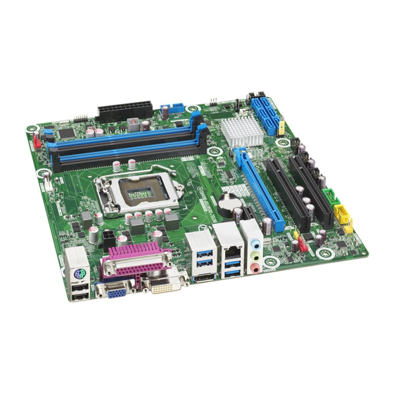
Product Description 1.1.2 Board Layout Figure 1 shows the location of the major components on Intel Desktop Board DQ87PG. Figure 1. Major Board Components... -
Page 14: Components Shown In Figure 1
Intel Desktop Board DQ87PG Technical Product Specification Table 2 lists the components identified in Figure 1. Table 2. Components Shown in Figure 1 Item/callout from Figure 1 Description Conventional PCI add-in card connector Conventional PCI add-in card connector Rear fan header... -
Page 15: Block Diagram
Product Description 1.1.3 Block Diagram Figure 2 is a block diagram of the major functional areas of the board. Figure 2. Block Diagram... -
Page 16: Online Support
This board supports processors with a maximum wattage of 95 W Thermal Design Power (TDP). The processors listed above are only supported when falling within the wattage requirements of Intel Desktop Board DQ87PG. See the Intel web site listed below for the most up-to-date list of supported processors. -
Page 17: Processor Graphics Subsystem
Product Description 1.3.1 Processor Graphics Subsystem The board supports graphics through either the processor Intel HD Graphics or a PCI Express x16 add-in graphics card. The board supports integrated graphics for processors with Intel HD Graphics. ® ® 1.3.1.1 Intel... -
Page 18: Audio Formats Supported By The Displayport Interface
Intel Desktop Board DQ87PG Technical Product Specification 1.3.1.3 Integrated Audio Provided by the DisplayPort Interface The DisplayPort interface from the PCH supports audio. The processor supports two High Definition audio streams on two digital ports simultaneously. Table 4 shows the specific audio technologies supported by the PCH. - Page 19 Product Description 1.3.1.8 PCI Express Graphics generation Intel Core processors support PCI Express 3.0, 2.x, and 1.x: PCI Express 3.0 with a raw bit rate of 8.0 GT/s results in an effective bandwidth of • 1 GB/s each direction per lane. The maximum theoretical bandwidth of the x16 interface is 16 GB/s in each direction, simultaneously, for a total bandwidth of 32 GB/s.
-
Page 20: System Memory
Intel Desktop Board DQ87PG Technical Product Specification System Memory The board has four DIMM sockets and supports the following memory features: • 1.5 V DDR3 SDRAM DIMMs with gold plated contacts, with the option to raise the voltage to support higher performance DDR3 SDRAM DIMMs. -
Page 21: Memory Configurations
/CS-025414.htm 1.4.1 Memory Configurations generation Intel Core processors support the following types of memory organization: Dual channel (Interleaved) mode. This mode offers the highest throughput for • real world applications. Dual channel mode is enabled when the installed memory capacities of both DIMM channels are equal. -
Page 22: Memory Channel And Dimm Configuration
Intel Desktop Board DQ87PG Technical Product Specification Figure 3 illustrates the memory channel and DIMM configuration. Figure 3. Memory Channel and DIMM Configuration NOTE For best memory performance always install memory in the blue DIMM sockets if installing only two DIMMs on your board. -
Page 23: Intel ® Q87 Express Chipset
USB 3.0 ports. This controller allows data transfers up to 5 Gb/s. The controller supports SuperSpeed (SS), high-speed (HS), full-speed (FS), and low-speed (LS) traffic on the bus. The Intel Q87 Express Chipset provides the USB controller for the USB 2.0/3.0 ports. The port arrangement is as follows: •... -
Page 24: Sata Interfaces
SSD performance levels. For more information on Intel Smart Response Technology, go to http://www.intel.com/support/chipsets/sb/CS-032826.htm NOTE In order to use supported RAID and Intel Smart Response Technology features, you must first enable RAID in the BIOS. -
Page 25: Real-Time Clock Subsystem
Product Description Real-Time Clock Subsystem A coin-cell battery (CR2032) powers the real-time clock and CMOS memory. When the computer is not plugged into a wall socket, the battery has an estimated life of three years. When the computer is plugged in, the standby current from the power supply extends the life of the battery. -
Page 26: Audio Subsystem
Intel Desktop Board DQ87PG Technical Product Specification Audio Subsystem The board supports Intel HD Audio via the Realtek ALC662 audio codec. The audio subsystem supports the following features: Advanced jack sense for the back panel audio jacks that enables the audio codec to •... -
Page 27: Audio Connectors And Headers
Product Description 1.8.2 Audio Connectors and Headers The board contains audio connectors and headers on both the back panel and the component side of the board. The component-side audio headers include front panel audio (a 2 x 5-pin header that provides mic in and line out signals for front panel audio connectors). -
Page 28: Lan Subsystem
LAN software and drivers http://downloadcenter.intel.com ® 1.9.1 Intel I217LM Gigabit Ethernet Controller The Intel I217LM Gigabit Ethernet Controller supports the following features: Network Features: Compliant with the 1 Gb/s Ethernet 802.3, 802.3u, 802.3z, 802.3ab specifications • • Multi-speed operation: 10/100/1000 Mb/s Full-duplex operation at 10/100/1000 Mb/s;... -
Page 29: Lan Subsystem Software
• Provides lower power usage to meet ENERGY STAR 5.2 and ErP specifications 1.9.2 LAN Subsystem Software LAN software and drivers are available from Intel’s World Wide Web site. For information about Refer to Obtaining LAN software and drivers http://downloadcenter.intel.com 1.9.3... -
Page 30: 1.10 Hardware Management Subsystem
Intel Desktop Board DQ87PG Technical Product Specification 1.10 Hardware Management Subsystem The hardware management features enable the board to be compatible with the Wired for Management (WfM) specification. The board has several hardware management features, including the following: • Thermal and voltage monitoring •... -
Page 31: Thermal Monitoring
Figure 6 shows the locations of the thermal sensors and fan headers. Item Description Rear chassis fan header Thermal diode, located on the processor die Processor fan header Front chassis fan header Thermal diode, located on the Intel Q87 PCH Figure 6. Thermal Sensors and Fan Headers... -
Page 32: Intel Vpro™ Technology
Intel I217LM Gigabit (10/100/1000 Mb/s) Ethernet LAN controller • BIOS/SPI Flash (96 Mb/s) • NOTE Software with AMT capability is required to take advantage of Intel AMT platform management capabilities. 1.10.5.1.1 Intel AMT Features The key features of Intel AMT include: Secure Out of Band (OOB) system management that allows remote management •... - Page 33 System Defense 2. In addition to the in-bound and out-bound packet filtering of • the previous generation, System Defense 2 is an Intel AMT feature that uses advanced heuristics to help protect against the propagation of worms through the use of preset packet filters. The number of new connections made to a specific port or IP address are counted over a specific time window.
- Page 34 Intel Active Management Technology (Intel AMT) technology/intel-amt/index.htm 1.10.5.1.2 Intel AMT Software and Drivers Intel AMT software and drivers are available from Intel’s World Wide Web site. The package usually consists of the following components: ® ® Intel Management Engine Interface (Intel ME Interface) •...
- Page 35 It accomplishes this by using a measured launch and leveraging Intel VT to produce a protected environment for the execution of sensitive applications.
- Page 36 Inside the firewall, this feature adapts Client Initiated Local Access (CILA); outside the firewall it uses Client Initiated Remote Access (CIRA). Many of the features of Intel AMT are available with Intel Fast Call for Help. These include Serial-over-LAN, IDE Redirection, KVM Remote Control, and PC Alarm Clock.
-
Page 37: Management Engine (Intel ® Me) Software And Drivers
1.11.1.1 Intel Management Engine “M” State LED The board has a blue-colored Intel ME “M” state LED (see Figure 7). The “M” state is based on Intel ME status, as follows: M0 = Intel ME is in full control in S0 •... -
Page 38: Location Of The Intel Me "M" State Led
Intel Desktop Board DQ87PG Technical Product Specification Figure 7. Location of the Intel ME “M” State LED... -
Page 39: 1.12 Power Management
Product Description 1.12 Power Management Power management is implemented at several levels, including: Software support through Advanced Configuration and Power Interface (ACPI) • Hardware support: • Power connector Fan headers LAN wake capabilities Instantly Available PC technology ... -
Page 40: Power States And Targeted System Power
Intel Desktop Board DQ87PG Technical Product Specification 1.12.1.1 System States and Power States Under ACPI, the operating system directs all system and device power state transitions. The operating system puts devices in and out of low-power states based on user preferences and knowledge of how devices are being used by applications. -
Page 41: Hardware Support
Product Description 1.12.1.2 Wake-up Devices and Events Table 11 lists the devices or specific events that can wake the computer from specific states. Table 11. Wake-up Devices and Events These devices/events can wake up the computer… …from this state Note 1) Power switch S3, S4, S5 (Note 1) -
Page 42: Power Connector
Intel Desktop Board DQ87PG Technical Product Specification LAN wake capabilities and Instantly Available PC technology require power from the +5 V standby line. NOTE The use of Wake from USB from an ACPI state requires an operating system that provides full ACPI support. -
Page 43: Lan Wake Capabilities
Product Description 1.12.2.3 LAN Wake Capabilities CAUTION For LAN wake capabilities, the +5 V standby line for the power supply must be capable of providing adequate +5 V standby current. Failure to provide adequate standby current when implementing LAN wake capabilities can damage the power supply. LAN wake capabilities enable remote wake-up of the computer through a network. -
Page 44: Wake From Usb
Intel Desktop Board DQ87PG Technical Product Specification 1.12.2.5 Wake from USB USB bus activity wakes the computer from an ACPI S3 state. NOTE Wake from USB requires the use of a USB peripheral that supports Wake from USB. 1.12.2.6 PME# Signal Wake-up Support When the PME# signal on the Conventional PCI bus is asserted, the computer wakes from an ACPI S3, S4, or S5 state (with Wake on PME enabled in the BIOS). -
Page 45: Location Of The Enhanced Standby Power Led
Product Description 3. During the next power on, a message will be displayed on the screen to notify the user that the power supply voltage rails have deviated outside the current ATX power supply specification and safe operating levels. 4. A message will be added to the BIOS Event Log for each event that takes place until the BIOS Event Log is cleared. - Page 46 Intel Desktop Board DQ87PG Technical Product Specification...
-
Page 47: Technical Reference
Technical Reference Memory Resources 2.1.1 Addressable Memory The board utilizes 32 GB of addressable system memory. Typically the address space that is allocated for Conventional PCI bus add-in cards, PCI Express configuration space, BIOS (SPI Flash device), and chipset overhead resides above the top of DRAM (total system memory). -
Page 48: Connectors And Headers
Intel Desktop Board DQ87PG Technical Product Specification Connectors and Headers CAUTION Only the following connectors and headers have overcurrent protection: back panel and front panel USB, and PS/2. The other internal connectors and headers are not overcurrent protected and should connect only to devices inside the computer’s chassis, such as fans and internal... -
Page 49: Back Panel Connectors
Technical Reference 2.2.1 Back Panel Connectors Figure 9 shows the location of the back panel connectors for the board. Item Description PS/2 port USB 2.0 ports VGA connector Parallel port DVI-D connector USB 3.0 connectors DisplayPort connector LAN port USB 3.0 connectors Line-in (surround) Line-out (front speakers) Mic-in (center/sub) -
Page 50: Component-Side Connectors And Headers
Intel Desktop Board DQ87PG Technical Product Specification 2.2.2 Component-side Connectors and Headers Figure 10 shows the locations of the component-side connectors and headers. Figure 10. Component-side Connectors and Headers... -
Page 51: Component-Side Connectors And Headers Shown In Figure 10
Technical Reference Table 12 lists the component-side connectors and headers identified in Figure 10. Table 12. Component-side Connectors and Headers Shown in Figure 10 Item/callout f rom Figure 10 Description Conventional PCI add-in card connector Conventional PCI add-in card connector Rear fan header S/PDIF out header PCI Express x16 add-in card connector... -
Page 52: Serial Port Connector
DSR (Data Set Ready) RTS (Request To Send) CTS (Clear To Send) RI (Ring Indicator) Key (no pin) Table 14. Front Panel Audio Connector for Intel HD Audio Signal Name Signal Name [Port 1] Left channel Ground [Port 1] Right channel... -
Page 53: Front Panel Usb 3.0 Connector
Technical Reference Table 17. Front Panel USB 3.0 Connector Signal Name Description Vbus Power IntA_P1_SSRX− USB3 ICC Port1 SuperSpeed Rx− IntA_P1_SSRX+ USB3 ICC Port1 SuperSpeed Rx+ Ground IntA_P1_SSTX− USB3 ICC Port1 SuperSpeed Tx− IntA_P1_SSTX+ USB3 ICC Port1 SuperSpeed Tx+ Ground IntA_P1_D−... -
Page 54: Chassis Intrusion Header
Intel Desktop Board DQ87PG Technical Product Specification Table 20. Chassis Intrusion Header Signal Name Intruder# Ground Table 21. Processor, Front, and Rear Chassis (4-Pin) Fan Headers Signal Name (Note) Ground +12 V FAN_TACH FAN_CONTROL Note: These fan headers use Pulse Width Modulation control for fan speed. -
Page 55: Processor Core Power Connector
Main power – a 2 x 12 connector. This connector is compatible with 2 x 10 • connectors previously used on Intel Desktop boards. The board supports the use of ATX12V power supplies with either 2 x 10 or 2 x 12 main power cables. When using a power supply with a 2 x 10 main power cable, attach that cable to the main power connector, leaving pins 11, 12, 23, and 24 unconnected. -
Page 56: Connection Diagram For Front Panel Connector
Intel Desktop Board DQ87PG Technical Product Specification 2.2.2.4 Front Panel Connector This section describes the functions of the front panel connector. Table 25 lists the signal names of the front panel connector. Figure 11 is a connection diagram for the front panel connector. -
Page 57: States For A One-Color Power Led
Technical Reference 2.2.2.4.3 Power/Sleep LED Header Pins 2 and 4 can be connected to a one- or two-color LED. Table 26 shows the possible states for a one-color LED. Table 27 shows the possible states for a two-color LED. Table 26. States for a One-Color Power LED LED State Description Power off/sleeping... -
Page 58: Connection Diagram For Front Panel Usb 2.0 Connectors
Intel Desktop Board DQ87PG Technical Product Specification 2.2.2.6 Front Panel USB Connectors Figure 12 and Figure 13 are connection diagrams for the front panel USB connectors. NOTE The +5 V DC power on the USB connectors is fused. • Use only a front panel USB connector that conforms to the USB 2.0 specification for •... -
Page 59: Bios Security Jumper
Technical Reference BIOS Security Jumper CAUTION Do not move the jumper with the power on. Always turn off the power and unplug the power cord from the computer before changing a jumper setting. Otherwise, the board could be damaged. Figure 14 shows the location of the jumper. The 3-pin jumper determines the BIOS Security program’s mode. -
Page 60: Bios Setup Security Jumper Settings
Intel Desktop Board DQ87PG Technical Product Specification Table 29. BIOS Setup Security Jumper Settings Function/Mode Jumper Setting Configuration Normal The BIOS uses current configuration information and passwords for booting. Lockdown The BIOS uses current configuration information and passwords for booting, except: •... -
Page 61: Intel ® Management Engine Bios Extension
MEBX) Reset Header ® The Intel MEBX reset header (see Figure 15) allows you to reset the Intel ME configuration to the factory defaults. Momentarily shorting pins 1 and 2 with a jumper (not supplied) will accomplish the following: Return all Intel ME parameters to their default values. -
Page 62: Mechanical Considerations
Intel Desktop Board DQ87PG Technical Product Specification Mechanical Considerations 2.5.1 Form Factor The board is designed to fit into an ATX-form-factor chassis. Figure 16 illustrates the mechanical form factor for the board. Dimensions are given in inches [millimeters]. The outer dimensions are 9.60 inches by 9.60 inches [243.84 millimeters by 243.84 millimeters]. -
Page 63: Electrical Considerations
+12 V2DC, and recommends 0A. This is to prevent PSU protection triggering during minimum loading. Intel recommends that system integrators and builders check the latest list of tested PSUs for ones capable of supporting the 4 generation Intel Core processor. This list may be found at: http://www.intel.com/go/powersupplies/. -
Page 64: Fan Header Current Capability
Intel Desktop Board DQ87PG Technical Product Specification For example, for a low power system consisting of a supported 45 W processor (see Section 1.3 on page 16 for a list of supported processors), 2 GB DDR3 RAM, integrated graphics, one SSD, one optical drive, and no extra onboard peripherals enabled, the minimum recommended power supply is a 320 W. -
Page 65: Thermal Considerations
Failure to ensure appropriate airflow may result in reduced performance of both the processor and/or voltage regulator or, in some instances, damage to the board. For a list of chassis that have been tested with Intel desktop boards please refer to the following website: http://www3.intel.com/cd/channel/reseller/asmo-na/eng/tech_reference/53211.htm... -
Page 66: Localized High Temperature Zones
Intel Desktop Board DQ87PG Technical Product Specification Figure 17 shows the locations of the localized high temperature zones. Item Description Processor voltage regulator area Processor Intel Q87 Express Chipset Figure 17. Localized High Temperature Zones... -
Page 67: Thermal Considerations For Components
For processor case temperature, see processor datasheets and processor specification updates Intel Q87 Express Chipset To ensure functionality and reliability, the component is specified for proper operation when Case Temperature is maintained at or below the maximum temperature listed in Table 34. -
Page 68: Reliability
50% electrical stress, 55 ºC ambient. The MTBF prediction is used to estimate repair rates and spare parts requirements. The MTBF data is calculated from predicted data at 55 ºC. The MTBF for the Intel Desktop Board DQ87PG is 258,525 hours. Environmental Table 36 lists the environmental specifications for the board. -
Page 69: Overview Of Bios Features
Overview of BIOS Features Introduction The board uses an Intel Visual BIOS that is stored in the Serial Peripheral Interface Flash Memory (SPI Flash) and can be updated using a disk-based program. The SPI Flash contains the Visual BIOS Setup program, POST, the PCI auto-configuration utility, LAN EEPROM information, and Plug and Play support. -
Page 70: Bios Flash Memory Organization
Selects an item (Moves the cursor up or down) <Tab> Selects a field (Not implemented) Mouse Allows control of all options and slider controls in Intel Visual BIOS <Enter> Executes command or selects the submenu <F9> Load the default configuration values for the current menu <F10>... -
Page 71: Resource Configuration
Overview of BIOS Features Resource Configuration 3.3.1 PCI Express Autoconfiguration The BIOS can automatically configure PCI Express devices. PCI Express devices may be onboard or add-in cards. Autoconfiguration lets a user insert or remove PCI Express cards without having to configure the system. When a user turns on the system after adding a PCI Express card, the BIOS automatically configures interrupts, the I/O space, and other system resources. -
Page 72: Bios Updates
Similar to performing a BIOS Recovery without removing the BIOS configuration jumper. Intel Visual BIOS Update Utility allows the user to select the BIOS .bio file from the • internet, USB device, hard disk drive, or other media. -
Page 73: Custom Splash Screen
The Intel Integrator’s Toolkit version 5 that is available from Intel can be used to create a custom splash screen. NOTE If you add a custom splash screen, it will share space with the Intel branded logo. For information about Refer to Intel Integrator Toolkit http://www.intel.com/go/itk... -
Page 74: Boot Options
Intel Desktop Board DQ87PG Technical Product Specification Boot Options In the BIOS Setup program, the user can choose to boot from a hard drive, optical drive, removable drive, or the network. The default setting is for the optical drive to be the first boot device, the hard drive second, removable drive third, and the network fourth. -
Page 75: Adjusting Boot Speed
It is possible to optimize the boot process to the point where the system boots so quickly that the Intel logo screen (or a custom logo splash screen) will not be seen. Monitors and hard disk drives with minimum initialization times can also contribute to a boot time that might be so fast that necessary logo screens and POST messages cannot be seen. -
Page 76: Power Button Menu
Intel Desktop Board DQ87PG Technical Product Specification 3.9.3 Power Button Menu The Power Button Menu can be accessed during power on if the user presses the power button and holds it down until three short beep sounds are emitted by the board piezoelectric speaker. -
Page 77: 3.11 Bios Security Features
Overview of BIOS Features During every POST, if a User hard disk drive password is set, POST execution will pause with the following prompt to force the user to enter the Master Key or User hard disk drive password: Enter Hard Disk Drive Password: Upon successful entry of the Master Key or User hard disk drive password, the system will continue with normal POST. -
Page 78: Supervisor And User Password Functions
Intel Desktop Board DQ87PG Technical Product Specification password is set, the computer boots without asking for a password. If both passwords are set, the user can enter either password to boot the computer. • For enhanced security, use different passwords for the supervisor and user passwords. -
Page 79: 3.12 Bios Performance Features
Overview of BIOS Features 3.12 BIOS Performance Features The BIOS includes the following options to provide custom performance enhancements when using 4 generation Intel Core processors in an LGA1150 socket. Processor maximum non-turbo ratio (processor multiplier can only be adjusted • down) Processor turbo ratio adjustment •... - Page 80 Intel Desktop Board DQ87PG Technical Product Specification...
-
Page 81: Beep Codes, Error Messages, And Post Codes
Beep Codes, Error Messages, and POST Codes BIOS Error Codes The BIOS provides two types of Error Code indications during POST: Beep codes • • Blink codes 4.1.1 BIOS Beep Codes Whenever a recoverable error occurs during POST, the BIOS causes the board’s speaker (Figure 1, J) to beep an error code describing the problem (see Table 43). -
Page 82: Bios Error Messages
Intel Desktop Board DQ87PG Technical Product Specification 4.1.2 Front-panel Power LED Blink Codes Whenever a recoverable error occurs during POST, the BIOS causes the board’s front panel power LED to blink an error code describing the problem (see Table 44). -
Page 83: Port 80H Power On Self Test (Post) Codes
Beep Codes, Error Messages, and POST Codes Port 80h Power On Self Test (POST) Codes During the POST, the BIOS generates diagnostic progress codes (POST codes) to I/O port 80h. If the POST fails, execution stops and the last POST code generated is left at port 80h. -
Page 84: Port 80H Post Codes
Intel Desktop Board DQ87PG Technical Product Specification Table 47. Port 80h POST Codes Port 80 Code Progress Code Enumeration ACPI S States 0x00,0x01,0x02,0x03,0x04,0x05 Entering S0, S2, S3, S4, or S5 state 0x10,0x20,0x30,0x40,0x50 Resuming from S2, S3, S4, S5 Security Phase (SEC) - Page 85 Beep Codes, Error Messages, and POST Codes Table 47. Port 80h POST Codes (continued) Port 80 Code Progress Code Enumeration PEI after MRC 0x2A Start to Program MTRR Settings 0x2B Done Programming MTRR Settings PEIMs/Recovery 0x31 Crisis Recovery has initiated 0x33 Loading recovery capsule 0x34...
- Page 86 Intel Desktop Board DQ87PG Technical Product Specification Table 47. Port 80h POST Codes (continued) Port 80 Code Progress Code Enumeration 0x60 BDS driver entry point initialize 0x61 BDS service routine entry point (can be called multiple times) 0x62 BDS Step2...
- Page 87 Beep Codes, Error Messages, and POST Codes Table 47. Port 80h POST Codes (continued) Port 80 Code Progress Code Enumeration Removable Media 0xB8 Resetting removable media 0xB9 Disabling removable media 0xBA Detecting presence of a removable media (IDE, CDROM detection etc.) 0xBB Enabling/configuring a removable media...
-
Page 88: Typical Port 80H Post Sequence
Intel Desktop Board DQ87PG Technical Product Specification Table 48. Typical Port 80h POST Sequence POST Code Description Initializing a chipset component Reading SPD from memory DIMMs Detecting presence of memory DIMMs Configuring memory Testing memory Loading recovery capsule Entered DXE phase... -
Page 89: Regulatory Compliance And Battery Disposal Information
Electromagnetic Compatibility (EMC) standards • Product certification markings • 5.1.1 Safety Standards Intel Desktop Board DQ87PG complies with the safety standards stated in Table 49 when correctly installed in a compatible host system. Table 49. Safety Standards Standard Title CSA/UL 60950-1 Information Technology Equipment –... -
Page 90: European Union Declaration Of Conformity Statement
European Union Declaration of Conformity Statement ® We, Intel Corporation, declare under our sole responsibility that the product Intel Desktop Board DQ87PG is in conformity with all applicable essential requirements necessary for CE marking, following the provisions of the European Council Directive 2004/108/EC (EMC Directive), 2006/95/EC (Low Voltage Directive), and 2002/95/EC (ROHS Directive). -
Page 91: Product Ecology Statements
Regulatory Compliance and Battery Disposal Information Polski Niniejszy produkt jest zgodny z postanowieniami Dyrektyw Unii Europejskiej 2004/108/EC, 206/95/EC i 2002/95/EC. Portuguese Este produto cumpre com as normas da Diretiva Européia 2004/108/EC, 2006/95/EC & 2002/95/EC. Español Este producto cumple con las normas del Directivo Europeo 2004/108/EC, 2006/95/EC &... -
Page 92: China Rohs
The China Ministry of Information Industry (MII) stipulates that a material Self Declaration Table (SDT) must be included in a product’s user documentation. The SDT for Intel Desktop Board DQ87PG is shown in Figure 19. Figure 19. Intel Desktop Board DQ87PG China RoHS Material... -
Page 93: Emc Regulations
Regulatory Compliance and Battery Disposal Information 5.1.5 EMC Regulations Intel Desktop Board DQ87PG complies with the EMC regulations stated in Table 50 when correctly installed in a compatible host system. Table 50. EMC Regulations Regulation Title FCC 47 CFR Part 15,... - Page 94 • Consult the dealer or an experienced radio/TV technician for help. Any changes or modifications to the equipment not expressly approved by Intel Corporation could void the user’s authority to operate the equipment. Tested to comply with FCC standards for home or office use.
-
Page 95: Energy Star* 5.2, E-Standby, And Erp Compliance
ENERGY STAR requirements. Intel has worked directly with these two governmental agencies in the definition of new requirements. Intel Desktop Board DQ87PG allows for a compliant system built to meet the following program requirements, including appropriate selection of an efficient power supply: ENErGY STAR v5.2, category D... -
Page 96: Regulatory Compliance Marks (Board Level)
Intel Desktop Board DQ87PG Technical Product Specification 5.1.7 Regulatory Compliance Marks (Board Level) Intel Desktop Board DQ87PG has the regulatory compliance marks shown in Table 51. Table 51. Regulatory Compliance Marks Description Mark UL joint US/Canada Recognized Component mark. Includes adjacent UL file number for Intel Desktop Boards: E210882. -
Page 97: Battery Disposal Information
Regulatory Compliance and Battery Disposal Information Battery Disposal Information CAUTION Risk of explosion if the battery is replaced with an incorrect type. Batteries should be recycled where possible. Disposal of used batteries must be in accordance with local environmental regulations. PRÉCAUTION Risque d'explosion si la pile usagée est remplacée par une pile de type incorrect. - Page 98 Intel Desktop Board DQ87PG Technical Product Specification PRECAUCIÓN Existe peligro de explosión si la pila no se cambia de forma adecuada. Utilice solamente pilas iguales o del mismo tipo que las recomendadas por el fabricante del equipo. Para deshacerse de las pilas usadas, siga igualmente las instrucciones del fabricante.
- Page 99 Regulatory Compliance and Battery Disposal Information AWAS Risiko letupan wujud jika bateri digantikan dengan jenis yang tidak betul. Bateri sepatutnya dikitar semula jika boleh. Pelupusan bateri terpakai mestilah mematuhi peraturan alam sekitar tempatan. OSTRZEŻENIE Istnieje niebezpieczeństwo wybuchu w przypadku zastosowania niewłaściwego typu baterii.
- Page 100 Intel Desktop Board DQ87PG Technical Product Specification 小心 如果更換的電池類型不正確,可能會有爆炸的危險。請盡可能將電池送至回收處。請依照當地的環保 規範來處理使用過的電池。 주의 배터리를 잘못된 종류로 교체할 경우 폭발 위험이 있습니다. 가능한 경우 배터리는 재활용해야 하며, 수명이 다한 배터리를 폐기할 때는 각 지역의 환경법을 따라야 합니다. THẬN TRỌNG Có nguy cơ xảy ra nổ nếu thay pin không đúng loại. Pin cần được tái chế nếu có thể...
- Page 101 Regulatory Compliance and Battery Disposal Information...
- Page 102 Intel Desktop Board DQ87PG Technical Product Specification...