Table of Contents
Advertisement
Advertisement
Chapters
Table of Contents

Related Manuals for Acer Aspire V3-731


Summary of Contents for Acer Aspire V3-731
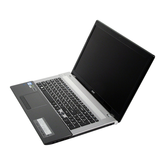
- Page 1 Acer V3-771/V3-771G SERVICEGUIDE...
-
Page 2: Revision History
Copyright © 2012 by Acer Incorporated. All rights reserved. No part of this publication may be reproduced, transmitted, transcribed, stored in a retrieval system, or translated into any language or computer language, in any form or by any means, electronic, mechanical, magnetic, optical, chemical, manual or otherwise, without the prior written permission of Acer Incorporated. -
Page 3: General Information
This service guide provides you with all technical information relating to the basic configuration for Acer’s global product offering. To better fit local market requirements and enhance product competitiveness, your regional office may have decided to extend the functionality of a machine (such as add-on cards, modems, or extra memory capabilities). -
Page 5: Table Of Contents
CHAPTER 1 Hardware Specifications Features ..........1-5 Operating System . - Page 6 Security ......... . 2-8 Boot.
- Page 7 Removing the Motherboard ......3-48 Removing the Thermal Module..... . . 3-52 Removing the CPU .
- Page 8 Touchpad Failure ........4-9 Internal & External Speaker Failure ....4-10 Microphone Failure .
- Page 9 Introduction ......... 8-3...
- Page 11 CHAPTER Hardware Specifications...
- Page 12 Features ..........1-5 Operating System .
- Page 13 BD Combo Drive Interface ........1-33 BD RW Drive Interface.
-
Page 15: Features
Hardware Specifications and Configurations Features The following is a brief summary of the computer’s many features: Operating System ® Genuine Windows 7 Home Premium 64-bit ® Genuine Windows 7 Home Basic 64-bit Platform ® ® Intel Core™ i3-2350M processor (3 MB L3 cache, 2.30 GHz.35W), Intel Core™... -
Page 16: Storage Subsystem
Regulator, Volume Leveler, Volume Maximizer, Intelligent EQ, Dialogue Enhancer, Surround ® Virtualizer for Headphones, Surround Virtualizer for Built-in Speakers, and Dolby Digital Output technologies Two built-in 20mm diameter stereo speakers and the Acer Tuba CineBass booster supporting low-frequency effects True-5.1-channel surround sound output ... -
Page 17: Optical Media Drive
BD-R DL, 6X DVD-R DL, 6X DVD+R DL, 6X DVD-RW, 6X BD-R, 6X BD-R DL, 5X DVD-RAM, 4X BD-R L to H, 2X BD-RE, 2X BD-RE DL, 24X CD-R, 24X CD-RW Communication Webcam Acer Video Conference, featuring: 1.3M webcam with 1280*1024 effective resolution ... -
Page 18: Dimensions And Weight
Dimensions and Weight Dimensions 414.8 (L) x 275 (W) x 34~34.65 (H) mm Weight 3.215 kg with 6 cell battery Power Adapter and Battery ACPI 3.0 CPU power management standard: supports Standby and Hibernation power-saving modes Power adapter 3-pin 65 W AC adapter: ... -
Page 19: Software
Microphone-in jack Ethernet (RJ-45) port DC-in jack for AC adapter Software Productivity Acer AUPEO OOBE offer Acer Edition Acer Backup Manager Acer ePower Management Acer eRecovery Management Acer Evernote Acer Identity Card ... -
Page 20: Environment
Gaming Acer Fooz Kids Wild Tangent WW Acer Edition Communication and ISP Skype Windows Live Essentials 2011 Web links and utilities Acer Accessory Store Bing Bar Bing Setup eBay Shortcut 2009 Internet Explorer 9 ... -
Page 21: Notebook Tour
Notebook Tour This section provides an overview of the features and functions of the notebook. Top Cover View Figure 1-1. Top Cover View Table 1-1. Top Cover View Icon Item Description Microphone Internal microphone for recording sound. Screen Also called Liquid-Crystal Display (LCD), displays computer output. -
Page 22: Keyboard View
Keyboard View Figure 1-2. Keyboard View Table 1-2. Keyboard View Icon Item Description Power button Turns the computer on and off Keyboard For entering data into your computer. Touchpad Touch-sensitive pointing device which functions like a computer mouse. Click buttons (left and The left and right buttons function like the left right) and right mouse buttons. -
Page 23: Closed Front View
Closed Front View Figure 1-3. Closed Front View Table 1-3. Closed Front View Icon Item Description Power indicator Indicates the computer’s power status. Battery indicator Indicates the computer’s battery status. 1. Charging: The light shows amber when the battery is charging. 2. -
Page 24: Left View
Left View Figure 1-4. Left View Table 1-4. Left View Icon Item Description Kensington lock slot Connects to a Kensington-compatible computer security lock. Wrap the computer security lock cable around an immovable object such as a table or handle of a locked drawer. -
Page 25: Right View
Right View Figure 1-5. Right View Table 1-5. Right View Icon Item Description Headphones/speaker/l Connects to audio line-out devices (e.g., speakers, ine-out jack headphones). Microphone jack Accepts inputs from external microphones. USB 2.0 ports Connect to USB 2.0 devices (e.g., USB mouse, USB camera). -
Page 26: Base View
Base View Figure 1-6. Base View Table 1-6. Base View Icon Item Description Battery release latch Releases the battery for removal. Insert a suitable tool into the latch and slide to release. Hard disk bay Houses the computer's hard disk (secured with screws). Memory Houses the computer's main memory. -
Page 27: Indicators
Indicators The computer has five easy-to-read status indicators. The following indicators are visible even when the computer cover is closed. Table 1-7. Indicators Icon Function Description Power indicator Indicates the computer’s power status. Battery indicator Indicates the computer’s battery status. 1. -
Page 28: Touchpad Basics
Touchpad Basics Figure 1-7. Touchpad Move finger across the TouchPad (1) to move the cursor. Press the left (2) and right (3) buttons located beneath the TouchPad to perform selection and execution functions. These two virtual buttons are the equivalent of the left and right buttons on a mouse. -
Page 29: Using The Keyboard
Using the Keyboard The keyboard contains an embedded numeric keypad, a separate cursor, windows key, lock function keys, special and full sized keys. Figure 1-8. Keyboard Lock Keys 1-19 Hardware Specifications and Configurations... -
Page 30: Lock Keys
Lock Keys The keyboard has three lock keys which the user can toggle on and off. Table 1-9. Lock Keys Lock key Description Caps Lock When on, all alphabetic characters are in uppercase. Num Lock Off by default. When On, internal keyboard acts as numeric key padlock. If an external keyboard or keypad is present, the Num Lock will have the following definitions: When On, the system boots with external keyboard/keypad Num Lock... -
Page 31: Windows Keys
Windows Keys The keyboard has two keys that perform Windows-specific functions. Windows Logo key Application key Table 1-10. Windows Keys Description Windows Logo Pressed alone, this key has the same effect as clicking on the Windows Start button; it launches the Start menu. It can also be used with other keys to provide a variety of functions. -
Page 32: Hotkeys
Hotkeys The computer uses hotkeys or key combinations to access most computer controls. To activate hotkeys, press and hold the <Fn> key before pressing the key in the combination. Figure 1-9. Keyboard Hotkeys Table 1-11. Hotkeys Hotkey Icon Function Description <Fn>... - Page 33 Table 1-11. Hotkeys (Continued) Hotkey Icon Function Description Volume down Decreases the sound volume. <Fn> + < ▽ > <Fn> +<Home> Play/Pause Play or pause a selected media file. <Fn> + <Pg Up> Stop Stop playing the selected media file. <Fn>...
-
Page 34: System Block Diagram
System Block Diagram VA70 BLOCK DIAGRAM DDR-III DDR3 1333/1600 MHz SO-DIMM*2 channel A PAGE 16 Sandy Bridge DDR3 1333/1600 MHz DDR-III dGPU Ivy Bridge PCIE X 16 channel B SO-DIMM*2 N13P GS/GL/GT PAGE 17 PAGE 3-10 USB2.0 PAGE 70~79 Camera FDI x 4 DMI x 4 HDMI... -
Page 35: Specification Tables
Specification Tables Computer specifications Item Metric Imperial Dimensions Length 414.8 mm 16.3 in Width 275.0 mm 10.8 in Height 34.6 mm 1.4 in Weight (equipped with optical 3.2 kg with HDD 7.0 lbs with HDD drive, flash drive, and battery) Input power Operating voltage 19V at 3.42A Max for 90W... - Page 36 System Board Major Chips Item Specification Core logic Intel Panther Point HM77 NVIDIA Optimus™ GeForce GT630M/640M/650M Atheros AR8151L USB 3.0 Intel Panther Point HM77 Embedded controller ITE 8518E Bluetooth Atheros AR9462(main chip of WLAN combo) Wireless FOXCONN T77H348.02 LITEON WCBN611AH-AA PCMCIA Audio codec Realtek ALC271X-VB6...
- Page 37 Processor Specifications Item CPU Speed Cores Mfg Tech Cache Size Package (GHz) i3-2350M 22nm BGA 1023 i3-2370M 22nm BGA 1023 i5-2450M 22nm BGA 1023 i5-2520M 22nm BGA 1023 i5-2540M 22nm BGA 1023 i7-2670QM 22nm BGA 1023 i3-3110M 22nm BGA 1023 i5-3210M 22nm BGA 1023...
- Page 38 DIS 35W CPU Fan True Value Table (Tj85/Tj90/Tj100/Tj105) Fan Speed Temperature Temperature Temperature Temperature (RPM) (Tj85) (Tj90) (Tj100) (Tj105) 2400 2599 3000 3297 3698 Throttling 0% Tj85:OS Critical shut down at 83°C; EC Force shut down at 84°C Tj90:OS Critical shut down at 88°C; EC Force shut down at 89°C Tj100:OS Critical shut down at 97°C;...
- Page 39 UMA CPU Fan True Value Table (Tj85/Tj90/Tj100/Tj105) CPU Temperature Fan Speed (RPM) 2400 2599 3004 3302 3698 Throttling 0% Tj85:OS Critical shut down at 83°C; EC Force shut down at 84°C Tj90:OS Critical shut down at 88°C; EC Force shut down at 89°C Tj100:OS Critical shut down at 98°C;...
- Page 40 Slot 1(MB) Slot 2(MB) Slot 3(MB) Slot 4(MB) Total Memory (MB) 2048 2048 4096 2048 2048 2048 6144 2048 2048 2048 6144 2048 2048 2048 6144 2048 2048 2048 6144 2048 2048 2048 2048 8192 4096 4096 4096 4096 4096 4096 4096 4096...
- Page 41 Support PXE Support WinFlash Wake on LAN from S3 Wake on LAN from S5 in AC mode System information Refer to Acer BIOS specification. LAN Interface Item Specification LAN Chipset Atheros AR8151L LAN connector type RJ45...
- Page 42 Hard Disk Drive (AVL components) Item Specification Vendor & Model Western Digital Western Digital TOSHIBA Name WD5000BPVT-22HX WD10JPVT-22A1YT MK1059GSMP Capacity (GB) 1000 1000 Bytes per sector 512/4096 512/4096 512/4096 Data heads Drive Format Height(mm) Disks Performance Specifications Spindle speed (RPM) 5400 5400 5400...
-
Page 43: Bd Combo Drive Interface
Item Specification Applicable disc format Applicable disc format CD: CD-DA, CD-ROM, CD-ROM XA, Photo CD (multi-session), Video CD, Cd-Extra (CD+), CD-text DVD: DVD-VIDEO, DVD-ROM, DVD-R (3.9GB, 4.7GB) DVD-R DL, DVD-RW, DVD-RAM, DVD+R, DVD+R DL, DVD+RW CD: CD-DA (Red Book) - Standard Audio CD & CD-TEXT CD-ROM (Yellow Book Mode1 &... -
Page 44: Bd Rw Drive Interface
Item Specification Applicable disc Applicable disc format CD: CD-DA, CD-ROM, CD-ROM XA, Photo CD format (multi-session), Video CD, Cd-Extra (CD+), CD-text DVD: DVD-VIDEO, DVD-ROM, DVD-R (3.9GB, 4.7GB) DVD-R DL, DVD-RW, DVD-RAM, DVD+R, DVD+R DL, DVD+RW CD: CD-DA (Red Book) - Standard Audio CD & CD-TEXT CD-ROM (Yellow Book Mode1 &... -
Page 45: Led 17.3
Item Specification Loading mechanism Load: Manual Release: (a) Electrical Release (Release Button) (b) Release by ATAPI command (c) Emergency Release Power Requirement Input Voltage 5 V +/- 5% (Operating) LED 17.3” Item Specification Vendor/model name AUO 17.3”HD 16:9 Color TFT-LCD/ B173RW01 V3 Screen Diagonal (mm) 438.4 Active Area (mm) -
Page 46: Graphics Controller
Resolution 16 bits 32 bits Intel NVIDIA 1360x768/60Hz 1366x768/60Hz 1440x900/60Hz 1600x900//60Hz Graphics Controller Item Specification VGA Chip NVIDIA Optimus™ GeForce GT630M/640M/650M with dedicated DDR3 VRAM Supports CUDA®, PhysX®, 3D Vision®, Microsoft® DirectX® 11, OpenGL® 4.1, OpenCL™ 1.1 Display Supported Resolution (GPU Supported Resolution) Resolution 16 bits 32 bits... -
Page 47: Display Supported Resolution (Lcd Panel Supported Resolution)
Display Supported Resolution (LCD panel Supported Resolution) Resolution 16 bits 32 bits Intel NVIDIA 800x600p/60Hz 1024x768p/60Hz 1152x864/60Hz 1280x600/60Hz 1280x720/60Hz 1280x768/60Hz 1280x800/60Hz 1360x768/60Hz 1366x768/60Hz 1440x900/60Hz 1600x900//60Hz Bluetooth Interface Item Specification Chipset Atheros AR9462 Data throughput 1 Mbps (GFSK) 2 Mbps (π/4-DQPSK) for EDR ... -
Page 48: Camera
Camera Item Specification Vendor and Model LITEON 10P2SF205 LITEON 11P2BF136 CHICONY CKFB15321004970LH SUYIN HF2015-A821-OV01 SUYIN HF1318-P88B-SN04 Type 1.3M WIFI Card Item Specification Vendor and Model FOXCONN T77H348.02 WCBN611AH-AA Wireless LAN Standards 802.11b/g/n Operating Frequency 2.4 GHz Form Factor Half-Mini card Host Interface PCI-Express Bus interface 4-layer design and single side... - Page 49 Item Specification Features Meets Microsoft WLP (Windows Logo Program) audio requirements High performance DACs with digital >110dB and analog 98dB (A-weighting) signal-to-noise High performance ADCs with digital > 100dB and analog 90dB (A-Weighting) signal-to-noise ratio Six DAC channels support 16/20/24-bit PCM format for 5.1 ...
-
Page 50: Audio Interface
Item Specification Amplifier Embedded Features 4 step gain control 2-W/Ch Output Power into 3- load from 5-V supply Fully Differential Input Low Supply Current and Shutdown selection Embedded de-pop circuit Audio Interface Item Specification Audio Controller Realtek ALC271X-VB6 Audio onboard or optional On board... -
Page 51: Usb Port
USB Port Item Specification USB compliance level USB 3.0, USB 2.0 EHCI Number of USB port(s) USB 3.0x2, USB 2.0x2 Location USB 3.0 two at left side USB 2.0 two at right side Output Current 1.0A for each connector HDMI Port Item Specification Compliance level... -
Page 52: Card Reader
Card Reader Item Specification Chipset REALTEK RTS5209-GR Package 48-pin LQFP Maximum supported size SD: 2T, MMC: 16G, miniSD: 16G Features Support SD, MMC, MMC plus, MS, xD, SDHC, SDXC UHS104 System LED Indicator Item Specification Power indicator Blue color solid on: System on ... -
Page 53: System Io Address Map
Hardware IRQ System function IRQ13 Numeric data processor IRQ81-IRQ 190 Microsoft ACPI-Compliant System IRQ10 Intel(R) 7 Series/C216 Chipset Family SMBus Host Controller – 1E22 IRQ16 Intel(R) 7 Series/C216 Chipset Family USB Enhanced Host Controller- 1E2D Intel(R) 7 Series/C216 Chipset Family PCI Express Root Port 2 –... - Page 54 I/O address (hex) System Function (shipping configuration) 003C – 003D Programmable interrupt controller 0040 – 0043 System timer 004E – 004F Motherboard resources 0050 – 0053 System timer 0060 – 0060 Standard PS/2 Keyboard 0061 – 0061 Motherboard resources 0062 – 0062 Microsoft ACPI-Compliant Embedded Controller 0063 –...
- Page 55 I/O address (hex) System Function (shipping configuration) 0458 – 047F Motherboard resources 04D0 – 04D1 Programmable interrupt controller 0500 – 057F Motherboard resources 0680 – 069F Motherboard resources 0D00 - FFFF PCI bus 1000 – 100F Motherboard resources 164E – 164F Motherboard resources 2000 –...
- Page 56 1-46 Hardware Specifications and Configurations...
- Page 57 CHAPTER System Utilities...
- Page 58 BIOS Setup Utility........2-3 Navigating the BIOS Utility .
-
Page 59: Bios Setup Utility
System Utilities BIOS Setup Utility A hardware configuration program built into a computer’s BIOS (Basic Input/Output System). Preconfigured and optimized so users do not need to run this utility. If configuration problems occur, users may need to run Setup. Refer to Chapter 4, Troubleshooting when problem arises. -
Page 60: Bios
BIOS The following is a description of the tabs found on the InsydeH20 Setup Utility screen: NOTE: NOTE: The screens provided are for reference only. Actual values may differ by model. Information This tab shows a summary of computer hardware information. Figure 2-1. - Page 61 Table 2-1 describes the parameters shown in Figure 2-1 Table 2-1. Parameters Parameter Description CPU Type The CPU type and speed of the system. CPU Speed The speed of the CPU. HDD Model Name The model name of HDD installed on primary IDE master. HDD Serial Number The serial number of HDD installed on primary IDE master.
-
Page 62: Main
Main This tab allows the user to set system time and date, enable or disable boot option and enable or disable recovery. Figure 2-2. BIOS Main Table 2-2 describes the parameters shown in Figure 2-2. Table 2-2. BIOS Main Parameter Description Format/Option System... - Page 63 Table 2-2. (Continued)BIOS Main Parameter Description Format/Option Quiet Boot The notebook shows an illustration called the OEM Enabled or Disabled screen during system boot instead of the traditional POST screen that shows the normal diagnostic messages. Network Enables, disables the system boot from LAN (remote Enabled or Disabled Boot server).
-
Page 64: Security
Security This tab shows parameters that safeguard and protect the computer from unauthorized use. Figure 2-3. BIOS Security Table 2-3 describes the parameters shown in Figure 2-3. Table 2-3. BIOS Security Parameter Description Option Supervisor Shows the setting of the supervisor password Clear or Password Is User Password Is... -
Page 65: Setting A Password
Setting a Password Perform the following to set the user or supervisor password: 1. Use the and keys to highlight the Set Supervisor Password parameter and press Enter key. The Set Supervisor Password box appears. Figure 2-4. Set Supervisor Password 2. -
Page 66: Changing A Password
Changing a Password 1. Use the and keys to highlight Set Supervisor Password and press the Enter. The Set Supervisor Password box appears. Figure 2-6. Set Supervisor Password 2. Type the current password in the Enter Current Password field and press Enter. 3. - Page 67 Figure 2-9. Setup Warning 2-11 System Utilities...
-
Page 68: Boot
Boot This tab allows changes to the order of boot devices used to load the operating system. Bootable devices include the: USB diskette drives Onboard hard disk drive DVD drive in the module bay Use and keys to select a device and press F5 or F6 to move it up or down the list. Figure 2-10. -
Page 69: Exit
Exit The Exit tab allows users to save or discard changes and quit the BIOS Utility. Figure 2-11. BIOS Exit Table 2-4 describes the parameters in Figure 2-11. Table 2-4. Exit Parameters Parameter Description Exit Saving Changes Exit System Setup and save changes to the system. Exit Discarding Changes Exit utility without saving setup data to. -
Page 70: Bios Flash Utilities
BIOS Flash Utilities BIOS Flash memory updates are required for the following conditions: New versions of system programs New features or options Restore a BIOS when it becomes corrupted. Use the Flash utility to update the system BIOS Flash ROM. NOTE: NOTE: Create a Crisis Recovery Disc, if one is not available, before the Flash utility is used. -
Page 71: Dos Flash Utility
DOS Flash Utility Perform the following to use the DOS Flash Utility: 1. Press F2 during boot to enter the Setup Menu. 2. Select Boot Menu to modify the boot priority order. Example: If using USB HDD to Update BIOS, move USB HDD to position 1. Figure 2-12. - Page 72 Figure 2-13. DOS Flash 4. In flash BIOS, the message Please do not remove AC Power Source is shown. NOTE: NOTE: If AC power is not connected, the following message (Figure 2-14) is shown. Figure 2-14. AC Power Warning NOTE: NOTE: Plug in the AC power to continue.
-
Page 73: Winflash Utility
WinFlash Utility Perform the following to use the WinFlash Utility: 1. Double click the WinFlash executable. 2. Click OK to begin the update. A progress screen is shown (Figure 2-15). Figure 2-15. InsydeFlash 2-17 System Utilities... -
Page 74: Remove Hdd/Bios Password Utilities
Remove HDD/BIOS Password Utilities This section provides details for removing HDD/BIOS passwords. Remove HDD Password Utilities This section provides details for removing HDD passwords. Remove HDD Password as follows: NOTE: NOTE: If the HDD password is incorrectly entered three times, an error is generated, you will see below menu (Figure 2-16). - Page 75 Enter the password from the Step 1 to unlock the HDD (Figure 2-19). Figure 2-19. Unlock Password NOTE: NOTE: After customer clearing the HDD password, HDD maybe in “Frozen” state. Please power off system. Then, power on to Win system, HDD Password will be in normal. Figure 2-20.
-
Page 76: Removing Bios Passwords
Removing BIOS Passwords To clear User or Supervisor passwords, open the Main door and remove the mylar from DIMM then use a metal instrument to short the RTCRST# point.(Figure 2-21 and Figure 2-22) Figure 2-21. CMOS Jumper Figure 2-22. CMOS Jumper 2-20 System Utilities... -
Page 77: Cleaning Bios Passwords
4. After press Y/y key, BIOS will clear BIOS password and reboot system. Figure 2-23. Clear BIOS Password The on screen message indicates the function success. NOTE: NOTE: This document is for Pegatron Acer project in 2012. 2-21 System Utilities... -
Page 78: Using Dmi Tools
Using DMI Tools The DMI (Desktop Management Interface) Tool copies BIOS information to EEPROM. Used in the DMI pool for hardware management. 1. Execute < MN.bat > to update SMBIOS Type 1 Manufacturer Name(Figure 2-23). Figure 2-24. Manufacture Name 2-22 System Utilities... - Page 79 2. Execute < PN.bat > to update SMBIOS Type 1 Product Name(Figure 2-24). Figure 2-25. Update Product Name 2-23 System Utilities...
- Page 80 3. Execute < SN.bat > to update SMBIOS Type 1 Serial Number(Figure 2-25). Figure 2-26. Update Serial Number 2-24 System Utilities...
- Page 81 4. Execute < AT.bat > to update SMBIOS Type 3 Asset Tag Number(Figure 2-26). Figure 2-27. Update Asset Tag 2-25 System Utilities...
- Page 82 5. Execute < RU.bat > to read SMBIOS Type 1 UUID(Figure 2-27). Figure 2-28. Read UUID 2-26 System Utilities...
- Page 83 6. Execute < WU.bat > to write SMBIOS Type 1 UUID(Figure 2-28). Figure 2-29. Write UUID 2-27 System Utilities...
- Page 84 7. Execute < GU.bat > to generate and write SMBIOS Type 1 UUID (Figure 2-29). Figure 2-30. Generate and write UUID 2-28 System Utilities...
-
Page 85: Lan Mac Eeprom Utility
LAN MAC EEPROM Utility LAN EEPROM Utility enables to change the MAC address. Perfer the following steps to use the LAN EEPROM Utility: 1. Create a DOS bootable USB HDD. 2. Copy the AN MAC EEPROM Utility to the HDD and remove the HDD form the computer. 3. - Page 86 8. Under DOS, run command “memcfg -c” to check current MAC address (Figure 2-32). Figure 2-32. Execute MAC Tool 9. Run command to program the MAC address (Figure 2-33). memcfg –p MAC.ini Figure 2-33. Program MAC addressScreen 2-30 System Utilities...
- Page 87 10. Run command “memcfg -c” to check the MAC address programmed correctly (Figure 2-34). Figure 2-34. MAC address changed 11. When this process has completed, exit to C root folder then reboot. 2-31 System Utilities...
- Page 88 2-32 System Utilities...
- Page 89 CHAPTER Machine Maintenance...
- Page 90 Machine Disassembly and Replacement ....3-5 Recommended Equipment ......3-5 Replacement Requirements .
- Page 91 Replacing the Thermal Module ......3-92 Replacing the Motherboard ......3-95 Replacing the IO Board .
-
Page 93: Machine Disassembly And Replacement
Machine Disassembly and Replacement This chapter contains step-by-step procedures on how to disassemble the notebook computer for maintenance and troubleshooting. Cable paths and positioning may not represent the actual model. During the removal and installation of the components, ensure all available cable channels and clips are used and that the cables are replaced in the same position. -
Page 94: Pre-Disassembly Instructions
Pre-disassembly Instructions Before proceeding with the disassembly procedure, make sure to do the following: 1. Turn off the power to the system and all peripherals. 2. Unplug the AC adapter and all power and signal cables from the system. Figure 3-1. AC Adapter 3. -
Page 95: Disassembly Process
Observe the order of the sequence to avoid damage to any of the hardware components. For example, when removing the mainboard, remove first the keyboard, and LCD module then disassemble the inside assembly frame in that order. Table 3-1. Main Screw List Screw Quantity Acer Part Number M3*3 M2.5*5 M2.5*7 M2*2.2+5.7 M1.6*2.5... -
Page 96: External Module Disassembly Process
External Module Disassembly Process Table 3-2. Screw List Step Screw Quantity Part No. HDD Module Disassembly M2*3 HDD Bracket Disassembly M3*3 WLAN Module Disassembly M2*3 ODD Module Disassembly M2*3 ODD Bracket Disassembly M2*3 External Modules Disassembly Flowchart Figure 3-2. External Module Disassembly Flowchart... -
Page 97: Removing The Memory Card
Removing the Memory Card 1. Press the memory card in to allow it to spring out. Figure 3-3. Memory Card 2. Pull the memory card out. Figure 3-4. Memory Card... -
Page 98: Removing The Battery
Removing the Battery 1. Shut down the operating system, close the LCD panel, then turn over the notebook and place it on a level platform. Figure 3-5. Bottom side 2. Use a phillips screwdriver to insert the pit of battery latch, release the latch to spring the battery. - Page 99 Figure 3-7. Battery Figure 3-8. Battery 3-11...
-
Page 100: Removing The Main Door
Removing the Main Door 1. Loose 9 captive screws on the main door.. Figure 3-9. Screws on Main Door 2. Dig out the top edge of main door with a finger, lift the top edge first. Figure 3-10. Main Door 3-12... - Page 101 3. Lift to remove the main door. Figure 3-11. Main Door Figure 3-12. Main Door 3-13...
-
Page 102: Removing The Memory Module
Removing the Memory Module 1. Use two fingers, push the memory module clips outwards to spring the memory. Figure 3-13. Memory Module 2. Pull out the memory from its slot. Figure 3-14. Memory Module 3-14... - Page 103 3. Use two fingers, push the memory module clips outwards to spring another memory bar. Figure 3-15. Memory Module 4. Pull out the memory from its slot. Figure 3-16. Memory Module 3-15...
- Page 104 Figure 3-17. Memory Module 3-16...
-
Page 105: Removing The Hdd Module
Removing the HDD Module 1. Remove 2 screws on HDD bracket. Figure 3-18. Screws on HDD Bracket Table 3-3. Screws Step Screw Quantity Screw Type HDD Module Disassembly M2*3 2. Pull the handling mylar to disconnect the HDD from motherboard. 3-17... - Page 106 Figure 3-19. HDD Module 3. Use two fingers to hold the notches of HDD bracket, lift to remove HDD module. Figure 3-20. HDD Module 4. Remove 4 screws on HDD bracket to separate the HDD from the bracket. Figure 3-21. HDD Module 3-18...
- Page 107 Figure 3-22. HDD Module Table 3-4. Screws Step Screw Quantity Screw Type HDD Disassembly M3*3 Figure 3-23. HDD Bracket 3-19...
- Page 108 Figure 3-24. HDD 5. Repeat the procedures above to remove the second HDD module. Figure 3-25. Second HDD Module 3-20...
-
Page 109: Removing The Wlan Card
Removing the WLAN Card 1. Use a pair of plastic tweezers to clamp the antenna cable connectors, disconnect 2 cables from the WLAN module. IMPORTANT: Note the connector positions of the Main (black) and Auxiliary (white) cables. Figure 3-26. WLAN Card 2. - Page 110 Table 3-5. Screws Step Screw Quantity Screw Type WLAN Module Disassembly M2*3 3. Pull the WLAN module out from its slot. Figure 3-28. WLAN Card Figure 3-29. WLAN Card 3-22...
-
Page 111: Removing The Odd Module
Removing the ODD Module 1. Remove 1 screw from the bottom case. Figure 3-30. ODD Module Table 3-6. Screws Step Screw Quantity Screw Type ODD Module Disassembly M2*3 2. Pull the ODD module completely out of the housing. 3-23... - Page 112 Figure 3-31. ODD Module 3. Pull the ODD bezel to separate it from the ODD. Figure 3-32. ODD Module Figure 3-33. ODD Bezel 4. Remove 2 screws to remove ODD bracket. 3-24...
- Page 113 Figure 3-34. ODD Bracket Table 3-7. Screws Step Screw Quantity Screw Type ODD Bracket Disassembly M2*3 Figure 3-35. ODD Bracket 3-25...
-
Page 114: Main Unit Disassembly Process
Main Unit Disassembly Process Main Unit Disassembly Flowchart Figure 3-36. Main Unit DIsassembly Flowchart Table 3-8. Screws Step Screw Quantity Part No. Top Case and Palmrest M2.5*7 Disassembly M2*3 M2*2 Touchpad Switch Board M2*3 Disassembly Top Case Module Disassembly M2.5*5 Speaker Module Disassembly M2*2.2+5.7 Power Switch Board... -
Page 115: Removing The Top Case Palmrest
Removing the Top Case Palmrest 1. Remove 19 screws(M2.5*7) , 5 screws(M2*3) and 2 screws(M2*2)on the Bottom case. Figure 3-37. Screws on Bottom Case Table 3-9. Screws Step Screw Quantity Screw Type Bottom Case Disassembly M2.5*7 (red cycled) M2*3 (blue cycled) M2*2 (yellow cycled) 2. - Page 116 Figure 3-38. Top Case Palmrest 3. Pry to release all latches, then lift the bottom edge of top case palmrest to reveal the touchpad switch board cable connector. Figure 3-39. Top Case Palmrest 4. Disconnect the cable from the motherboard. 3-28...
- Page 117 Figure 3-40. Touchpad Switch Board FFC 5. Romove the top case palmrest Figure 3-41. Top Case Palmrest 3-29...
-
Page 118: Removing The Touchpad Switch Board
Removing the Touchpad Switch Board 1. Turn over the top case palmrest. Tear off the touchpad switch board cable from the touchpad. Figure 3-42. Touchpad Switch Board FFC 2. Disconnect the touchpad FFC from touchpad. Figure 3-43. Touchpad FFC 3-30... - Page 119 3. Tear off the touchpad FFC from touchpad. Figure 3-44. Touchpad FFC 4. Remove 2 screws from touchpad switch board. Figure 3-45. Touchpad Switch Board Table 3-10. Screws Step Screw Quantity Screw Type Touchpad Switch Board M2*3 Disassembly 3-31...
- Page 120 5. Lift to remove touchpad switch board. Figure 3-46. Touchpad Switch Board 3-32...
-
Page 121: Removing The Top Case
Removing the Top Case 1. Disconnect the power switch board cable from motherboard. Figure 3-47. Power Switch Board FFC 2. Disconnect the speaker cable from motherboard. Figure 3-48. Speaker Cable 3. Remove 1 screw from the keyboard bracket. 3-33... - Page 122 Figure 3-49. Keyboard Bracket Screw Table 3-11. Screws Step Screw Quantity Screw Type Top Case Disassembly M2.5*5 IMPORTANT: Do not forget to remove this screw. 4. Use a plastic pry slice to insert to the gap between top case and bottom case, pry to release all latches.
- Page 123 5. Lift the upper edge of top case to an about 60-degree angle to reveal the keyboard connector. Figure 3-51. Top Case 6. Disconnect the keyboard cable from motherboard. Figure 3-52. Keyboard cable 7. Lift to remove the top case. 3-35...
- Page 124 Figure 3-53. Top Case Module 3-36...
-
Page 125: Removing The Speaker Module
Removing the Speaker Module 1. Turn over the top case module. Tear off the adhesive paper from speaker cable. Figure 3-54. Adhesive Paper 2. Tear off the keyboard bracket mylar, pull out speaker cable from its position groove. Figure 3-55. Speaker Cable 3-37... - Page 126 3. Remove 4 screws from the speakers. Figure 3-56. Screws on Speakers Figure 3-57. Screws on Speakers Table 3-12. Screws Step Screw Quantity Screw Type Speaker Module Disassembly M2*2.2+5.7 3-38...
- Page 127 4. Lift to remove the speaker module. Figure 3-58. Speaker Module 3-39...
-
Page 128: Remove The Power Switch Board
Remove the Power Switch Board 1. Tear off the keyboard bracket mylar, tear off the power switch board cable from the keyboard bracket. Figure 3-59. Power Switch Board Cable 2. Remove 2 screws from power switch board. 3-40... - Page 129 Figure 3-60. Power Switch Board Table 3-13. Screws Step Screw Quantity Screw Type Power Switch Board M2*3 Disassembly 3. Lift to remove the power switch board from top case. Figure 3-61. Power Switch Board 3-41...
-
Page 130: Removing The Keyboard Bracket
Removing the Keyboard Bracket 1. Remove 6 screws(M2*3) and 9 screws(M1.6*2.5) from the keyboard bracket. Figure 3-62. Screws on Keyboard Bracket Table 3-14. Screws Step Screw Quantity Screw Type Keyboard Bracket M2*3 Disassembly M1.6*2.5 3-42... - Page 131 2. Push the keyboard bracket forward to release all latches. Figure 3-63. Keyboard Bracket 3. Lift the top edge of keyboard bracket first. Figure 3-64. Keyboard Bracket 3-43...
- Page 132 4. Lift the keyboard bracket by passing keyboard cable through the cable slot. Figure 3-65. Keyboard Cable IMPORTANT: Take care not to damage the cable during removal. 5. Remove the keyboard bracket. Figure 3-66. Keyboard Bracket 3-44...
-
Page 133: Removing The Keyboard
Removing the Keyboard 1. Lift to separate the keyboard from the top case. Figure 3-67. Keyboard on Top Case Figure 3-68. Keyboard 3-45... -
Page 134: Removing The Io Board
Removing the IO Board 1. Disconnect the IO board cable from motherboard. Figure 3-69. IO Board cable connector 2. Tear off the IO board cable from bottom case. Figure 3-70. IO Board Cable 3-46... - Page 135 3. Remove 1 screw from IO board. Figure 3-71. IO Board Table 3-15. Screws Step Screw Quantity Screw Type IO Board Disassembly M2.5*5 4. Lift the left edge of IO board first, and pull out the board from connector holes of bottom case.
-
Page 136: Removing The Motherboard
Removing the Motherboard 1. Close the LCD panel and turn over the machine. Lift the DC-in cable connector perpendicularly to disconnect them from motherboard. Figure 3-73. DC-in cable connector 2. Turn over the machine and open the LCD panel. Lift the LVDS cable connector perpendicularly to disconnect it from motherboard. - Page 137 3. Tear off the LVDS cable from motherboard. Figure 3-75. LVDS Cable 4. Tear off the LED acetate fabric from the LED pipe. Figure 3-76. LED Acetate Fabric 3-49...
- Page 138 5. Remove 4 screws from motherboard and thermal fan. Figure 3-77. Motherboard Table 3-16. Screws Step Screw Quantity Screw Type Motherboard Disassembly M2.5*5 6. Lift the right edge of motherboard first to pull out the motherboard from the connector holes of bottom case. 3-50...
- Page 139 Figure 3-78. Motherboard Figure 3-79. Motherboard 3-51...
-
Page 140: Removing The Thermal Module
Removing the Thermal Module 1. Disconnect the fan cable from motherboard. Figure 3-80. Thermal module 2. Remove 6 screws from the thermal moudle. Figure 3-81. Thermal module Table 3-17. Screws Step Screw Quantity Screw Type Thermal module Disassembly M2*3 3-52... - Page 141 3. Lift to remove the thermal module. Figure 3-82. Thermal Module 3-53...
-
Page 142: Removing The Cpu
Removing the CPU 1. Use a flat-head screwdriver to insert to the CPU socket lock slot, rotate the slot along anticlock direction to 180 degrees. Figure 3-83. CPU Socket 2. Eject the air in the rubber handle of vacuum pump. Figure 3-84. - Page 143 3. Press the vacuum pump on CPU die, release the rubber handle and lift to remove CPU. Figure 3-85. Vacuum Pump 3-55...
-
Page 144: Removing The Bottom Case
Removing the Bottom Case 1. Tear off the conductive fabric of LVDS cable, pull out LVDS cable and antenna cables from position groove of bottom case. Figure 3-86. Cables on Bottom Case 3-56... - Page 145 Figure 3-87. Cables on Bottom Case 2. Pull out DC-in cable from position groove and lift the connector to remove DC-in cable. 3-57...
- Page 146 Figure 3-88. DC-in Cable 3. Remove 4 screws from the hinges. Figure 3-89. Screws on Hinges 3-58...
- Page 147 Figure 3-90. Screws on Hinges Table 3-18. Screws Step Screw Quantity Screw Type Bottom Case Disassembly M2.5*5 3-59...
- Page 148 4. Lift LCD module to separate it from bottom case. Figure 3-91. Bottom Case Figure 3-92. Bottom Case 3-60...
-
Page 149: Lcd Module Disassembly Process
LCD Module Disassembly Process LCD Module Disassembly Flowchart Figure 3-93. LCD Module Disassembly Flowchart Table 3-19. Screws Step Screw Quantity Part No. LCD Bezel Disassembly M2.5*5 LCD Panel Disassembly M2.5*5 LCD Hinges Disassembly M2*3 3-61... -
Page 150: Removing The Lcd Bezel
Removing the LCD Bezel 1. Use a pair of tweezers to remove 2 screw mylar on LCD bezel. Figure 3-94. Screw Mylar on LCD Bezel Figure 3-95. Screw Mylar on LCD Bezel 2. Remove 2 screws on LCD bezel. 3-62... - Page 151 Figure 3-96. Screws on LCD Bezel Figure 3-97. Screws on LCD Bezel Table 3-20. Screws Step Screw Quantity Screw Type LCD Bezel Disassembly M2.5*5 3-63...
- Page 152 3. Use a plastic pry slice to insert to the crevice between LCD bezel and LCD cover, pry to release all latches. Figure 3-98. LCD Bezel 4. Lift to remove the LCD bezel. Figure 3-99. LCD Bezel 3-64...
- Page 153 Figure 3-100. LCD Bezel 3-65...
-
Page 154: Removing The Lcd Panel
Removing the LCD Panel 1. Disconnect the cable from the camera. Figure 3-101. Camera Connector 2. Use a pair of tweezers to pry up the microphone from LCD cover. Figure 3-102. Microphone 3. Pull out the LVDS cable from position groove. 3-66... - Page 155 Figure 3-103. LVDS Cable 4. Remove 6 screws on LCD hinges. Figure 3-104. LCD Panel Table 3-21. Screws Step Screw Quantity Screw Type LCD Panel Disassembly M2.5*5 3-67...
- Page 156 5. Lift to separate LCD panel from LCD cover. Figure 3-105. LCD Module 3-68...
-
Page 157: Removing The Hinges
Removing the Hinges 1. Remove 8 screws to separate the hinges from LCD panel. Figure 3-106. LCD Hinge 3-69... - Page 158 Figure 3-107. LCD Hinge Table 3-22. Screws Step Screw Quantity Screw Type LCD Hinge Disassembly M2*3 3-70...
-
Page 159: Removing The Camera
Removing the Camera 1. Lift to remove the camera from LCD cover carefully. Figure 3-108. Camera Figure 3-109. Camera 3-71... -
Page 160: Removing The Lvds Combo Cable
Removing the LVDS Combo Cable 1. Turn over the LCD panel to reveal LVDS Combo cable. Figure 3-110. LVDS Combo Cable on LCD Panel 2. Tear off the adhesive paper from LVDS Combo cable and LCD panel. Figure 3-111. LVDS Combo Cable on LCD Panel 3. - Page 161 Figure 3-112. LVDS Combo Cable on LCD Panel 4. Tear off the LVDS Combo cable from the bottom of LCD panel. Figure 3-113. LVDS Combo Cable on LCD Panel 5. Tear off the transparent handle tape of LVDS connector from LCD panel. 3-73...
- Page 162 Figure 3-114. LVDS Combo Cable on LCD Panel 6. Tear off the conductive fabric of LVDS connector from LCD panel. Figure 3-115. LVDS Combo Cable on LCD Panel 7. Disconnect the LVDS cable from LCD panel to remove it. 3-74...
- Page 163 Figure 3-116. LVDS Combo Cable on LCD Panel Figure 3-117. LVDS Combo Cable 3-75...
-
Page 164: Lcd Reassembly Procedure
LCD Reassembly Procedure Replacing the Camera 1. Position the camera on the LCD cover. Figure 3-118. Camera 3-76... -
Page 165: Replacing The Lcd Panel
Replacing the LCD Panel 1. Connect the LVDS cable to LVDS connector of LCD panel. Figure 3-119. LVDS Connector 2. Adhere the transparent handle tape on LCD panel. Figure 3-120. LVDS Connector 3-77... - Page 166 3. Pull the LVDS cable right and adhere it on the bottom of LCD panel. Figure 3-121. LCD Panel 4. Pull the camera cable up and adhere it on the top of LCD panel. Figure 3-122. LCD Panel 5. Adhere the waterproof tape to fix the camera cable on LCD panel. 3-78...
- Page 167 Figure 3-123. LCD Panel 6. Turn over the LCD panel. Consolidate the hinges and the LCD panel with 8 screws. Figure 3-124. LCD Panel 3-79...
- Page 168 Figure 3-125. LCD Panel Table 3-23. Screws Step Screw Quantity Screw Type LCD Hinge Assembly M2*3 CAUTION: Distinguish the left and right hinge before assembling. 7. Replace the top edge of LCD panel on LCD cover, then lay the bottom edge down to position LCD hinges.
- Page 169 Figure 3-126. LCD Panel 8. Consolidate the LCD panel and LCD cover with 6 screws. 3-81...
- Page 170 Figure 3-127. LCD Panel Table 3-24. Screws Step Screw Quantity Screw Type LCD Panel Assembly M2.5*5 9. Route LVDS cable in the position groove of LCD cover. Figure 3-128. LVDS Cable 10. Connect CMOS cable to the camera, press the microphone on the top edge of LCD cover. 3-82...
- Page 171 Figure 3-129. Camera Connector and Microphone 3-83...
-
Page 172: Replacing The Lcd Bezel
Replacing the LCD Bezel 1. Position LCD bezel on LCD cover, press the edges of LCD bezel to lock all latches. Figure 3-130. LCD Bezel 2. Consolidate LCD bezel and LCD cover with 2 screws. Figure 3-131. Screws on LCD Bezel 3-84... - Page 173 Figure 3-132. Screws on LCD Bezel Table 3-25. Screws Step Screw Quantity Screw Type LCD Bezel Assembly M2.5*5 3. Cover 2 screw mylar on bezel screws. Figure 3-133. Screw Mylar on LCD Bezel 3-85...
- Page 174 Figure 3-134. Screw Mylar on LCD Bezel 3-86...
-
Page 175: Replacing The Bottom Case
Replacing the Bottom Case 1. Open the hinges to an about 75-degree angle to the LCD panel, replace LCD module on the bottom case by aiming the position pillars of bottom case at the position holes of hinges. Figure 3-135. Bottom Case 2. - Page 176 Figure 3-137. Screws on Hinges Table 3-26. Screws Step Screw Quantity Screw Type Bottom Case Assembly M2.5*5 3. Route antenna cables and LVDS cable in position groove of bottom case, adhere the conductive fabric to fix LVDS cable. Replace DC-in cable in the position groove of bottom case.
- Page 177 Figure 3-138. Cables on Bottom Case Figure 3-139. Cables on Bottom Case 3-89...
-
Page 178: Replacing The Cpu
Replacing the CPU 1. Use a vacuum pump to suck up CPU and position it on CPU socket by aiming the golden triangle on CPU at the triangle mark on CPU socket. Figure 3-140. CPU 2. Use a flat-head screwdriver to insert to the slot of CPU socket lock, rotate the slot clockwise to 180 degrees. - Page 179 Figure 3-142. CPU Socket Locked Position 3-91...
-
Page 180: Replacing The Thermal Module
Replacing the Thermal Module IMPORTANT: Apply an appropriate thermal grease and ensure all heat pads are in place before replacing the thermal module. 1. Align the screw holes on the thermal module and mainboard then replace the module. Keep the module as level as possible to spread the thermal grease evenly. Figure 3-143. - Page 181 Figure 3-144. Thermal Module Table 3-27. Screws Step Screw Quantity Screw Type. Thermal module Assembly M2*3 3. Replace the other 2 diagonal screws on the thermal block spring, tighten all screws slowly and alternately to fix thermal module. Figure 3-145. Thermal Module Table 3-28.
- Page 182 Figure 3-146. Thermal Fan Cable 3-94...
-
Page 183: Replacing The Motherboard
Replacing the Motherboard 1. Turn over the motherboard. Replace the motherboard by inserting the IO conncetors to corresponding holes on bottom case, then lay the motherboard down to position it. Figure 3-147. Motherboard 2. Consolidate the motherboard and bottom case with 4 screws. 3-95... - Page 184 Figure 3-148. Motherboard Table 3-29. Screws Step Screw Quantity Screw Type Motherboard Assembly M2.5*5 3. Connect the LVDS cable to motherboard and paste the cable fabric. Figure 3-149. Motherboard 3-96...
- Page 185 4. Paste the LED acetate fabric on the LED pipe. Figure 3-150. LED Acetate Fabric 5. Close the LCD panel and turn over the machine. Press the DC-in connector perpendicularly to connect the cable to motherboard. Figure 3-151. DC-in Cable Connector 3-97...
-
Page 186: Replacing The Io Board
Replacing the IO Board 1. Turn over the machine and open the LCD panel. Position the IO board on bottom case by aiming the IO connectors at corresponding holes of bottom case first. Figure 3-152. IO Board 2. Lay the IO board down to position it on bottom case. Figure 3-153. - Page 187 3. Consolidate the IO board with 1 screw. Figure 3-154. IO Board Table 3-30. Screws Step Size Quantity Screw Type IO Board Assembly M2.5*5 4. Connect the IO board cable to motherboard. Figure 3-155. IO Board Cable 3-99...
-
Page 188: Replacing The Keyboard
Replacing the Keyboard 1. Turn over the keyboard and positon it on the back side of top case. Figure 3-156. Keyboard 2. Cover the keyboard bracket on the keyboard by passing keyboard cable through the cable slot of bracket first. Figure 3-157. - Page 189 and top case. Figure 3-158. Keyboard Bracket 4. Consolidate the keyboard bracket and the top case with 6 screws(M2*3) and 9 screws(M1.6*2.5). 3-101...
- Page 190 Figure 3-159. Keyboard Bracket Table 3-31. Screws Step Screw Quantity Screw Type Keyboard Bracket Assembly M2*3(red cycled) M1.6*2.5(blue cycled) 3-102...
-
Page 191: Replacing The Power Switch Board
Replacing the Power Switch Board 1. Replace the power switch board on the top case by aiming the position pillars of top case at the position holes of the board. Figure 3-160. Power Switch Board 2. Consolidate the power switch board with 2 screws. 3-103... - Page 192 Figure 3-161. Power Switch Board Table 3-32. Screws Step Screw Quantity Screw Type Power Switch Board Assembly M2*3 3. Cover the keyboard bracket mylar to fix the power switch board cable. Figure 3-162. Power Switch Board Cable 3-104...
-
Page 193: Replacing The Speaker Module
Replacing the Speaker Module 1. Position the speakers on the top case. Figure 3-163. Speaker Figure 3-164. Speaker 3-105... - Page 194 2. Consolidate the speakers with 4 screws. Figure 3-165. Speaker Figure 3-166. Speaker Table 3-33. Screws Step Screw Quantity Screw Type Speaker Module Assembly M2*2.2+5.7 3-106...
- Page 195 3. Route speaker cable in position groove of top case, cover the keyboard bracket mylar to fix the cable. Figure 3-167. Speaker Cable 4. Adhere the mylar on top case to fix speaker cable. Figure 3-168. Speaker Cable 3-107...
-
Page 196: Replacing The Top Case
Replacing the Top Case 1. Turn over the top case module. Place the top case module on the bottom case with an about 45-degree angle. Connect the keyboard cable to the motherboard. Figure 3-169. Keyboard Cable 2. Lay the top case module down to position it on the bottom case. Figure 3-170. - Page 197 3. Press the edges of top case to lock all latches. Then consolidate the top case with 1 screw. Figure 3-171. Top Case Module Table 3-34. Screws Step Screw Quantity Screw Type Top Case Module Assembly M2.5*5 4. Connect the power switch board cable and speaker cable to the motherboard. 3-109...
- Page 198 Figure 3-172. Power Switch Board Cable and Speaker Cable 3-110...
-
Page 199: Replacing The Top Case Palmrest
Replacing the Top Case Palmrest 1. Position the touchpad switch board on the back side of top case palmrest. Figure 3-173. Touchpad Switch Board 2. Consolidate the touchpad switch board with 2 screws. 3-111... - Page 200 Figure 3-174. Touchpad Switch Board Table 3-35. Screws Step Screw Quantity Screw Type Touchpad Switch Board M2*3 Assembly 3. Connect the touchpad cable to the touchpad. Figure 3-175. Touchpad Cable 4. Turn over the top case palmrest. Place the top case palmrest on the bottom case with an about 45-degree angle.
- Page 201 Figure 3-176. Touchpad Switch Board Cable 5. Lay down the top case palmrest to position it on the bottom case. Figure 3-177. Top Case Palmrest 6. Press the edges of top case palmrest to lock all latches. 3-113...
- Page 202 Figure 3-178. Top Case Palmrest 7. Close the LCD panel and turn over the machine. Tighten 19 screws(M2.5*7) , 5 screws(M2*3) and 2 screws(M2*2)on the bottom case. 3-114...
- Page 203 Figure 3-179. Screws on Bottom Case Table 3-36. Screws Step Screw Quantity Screw Type Top Case and Top Case M2.5*7 (red cycled) Palmrest Assembly M2*3 (blue cycled) M2*2(yellow cycled) 3-115...
-
Page 204: Replacing The Odd Module
Replacing the ODD Module 1. Consolidate the ODD bracket and ODD with 2 screws. Figure 3-180. ODD Bracket Table 3-37. Screws Step Screw Quantity Screw Type ODD Bracket Assembly M2*3 2. Combine the ODD bezel with ODD by inserting the bezel to the drive’s front panel. 3-116... - Page 205 Figure 3-181. ODD Bezel 3. Turn over the ODD module. Figure 3-182. ODD Module 3-117...
- Page 206 4. Insert the ODD module to the housing of bottom case. Consolidate the ODD bracket with 1 screw. Figure 3-183. ODD Module Table 3-38. Screws Step Screw Quantity Screw Type ODD Module Assembly M2*3 3-118...
-
Page 207: Replacing The Wlan Card
Replacing the WLAN Card 1. Insert the WLAN card to its slot on motherboard with a 30-degree angle, press down the card and release it three times for perfect contact of golden fingers. Figure 3-184. WLAN Card 2. Press down the WLAN card and consolidate it with 1 screw. Figure 3-185. - Page 208 Table 3-39. Screws Step Screw Quantity Screw Type WLAN Card Assembly M2*3 3. Connect the antenna cables to the WLAN card. Figure 3-186. WLAN Card IMPORTANT: The black cable connector is on the left and the white cable connector is on the right.
-
Page 209: Replacing The Hdd Module
Replacing the HDD Module 1. Consolidate the HDD and HDD bracket with 4 screws. Figure 3-187. HDD Bracket Figure 3-188. HDD Bracket 3-121... - Page 210 Table 3-40. Screws Step Screw Quantity Screw Type HDD Bracket Assembly M3*3 2. Place the HDD module into the left housing of bottom case. Figure 3-189. HDD Module NOTE: NOTE: The left housing enables HDD with the height of 12.5 mm. 3.
- Page 211 Figure 3-190. HDD Module 4. Consolidate the HDD module with 2 screws. Figure 3-191. HDD Module Table 3-41. Screws Step Screw Quantity Screw Type HDD Module Assembly M2*3 3-123...
- Page 212 5. Repeat the procedures above to assemble the second HDD module in the right housing of bottom case. NOTE: NOTE: The right housing enables HDD with the height of 9.5 mm. 3-124...
-
Page 213: Replacing The Dimm Module
Replacing the DIMM Module 1. Insert one memory bar to the socket on motherboard with a 45-degree angle, press down the DIMM and release it three times for perfect contact of golden fingers. Figure 3-192. DIMM Module 2. Press down the DIMM until it clicks into the spring latches. Figure 3-193. - Page 214 Figure 3-194. DIMM Module 4. Press down the DIMM until it clicks into the spring latches. Figure 3-195. DIMM Module 3-126...
-
Page 215: Replacing The Main Door
Replacing the Main Door 1. Replace the bottom edge of main door first and press down the top edge. Figure 3-196. Main Door 2. Tighten 9 captive screws to consolidate the main door and the bottom case. Figure 3-197. Screws on Main Door 3-127... -
Page 216: Replacing The Battery
Replacing the Battery 1. Place the top edge of the battery to its housing, press down the bottom edge to lock the spring latch. Figure 3-198. Battery Figure 3-199. Battery 3-128... - Page 217 CHAPTER Troubleshooting...
- Page 218 Introduction ......... 4-3 General Information .
-
Page 219: Introduction
NOTE: NOTE: The diagnostic tests are intended for Acer products only. Non-Acer products, prototype cards, or modified options can give false errors and invalid system responses. 1. Obtain as much detailed information as possible about the problem. -
Page 220: Power On Issues
Power On Issues If the system does not power on, perform the following, one at a time, to correct the problem. Do not replace a non-defective FRU: Start Check AC/Battery Swap AC/Battery Power on Check Swap Daughter BD & Daughter BD &... -
Page 221: No Display Issues
No Display Issues If the Display does not work, perform the following, one at a time. Do not replace a non-defective FRU: START LCD Moduel Power On? Power On Issue Replace LCD Panel/LCD Cable Ext.DDRRAM Module well Check Connection connected? Replace Ext DDRRAM Ext. -
Page 222: Lcd Failure
5. Connect an external monitor to the computer and switch between the internal display and the external display is by pressing Fn+F5. 6. If the POST or video appears on the external display only, refer to Failure. 7. Disconnect power and all external devices including port replicators or docking stations. Remove any memory cards and CD/DVD discs. -
Page 223: Lcd Failure
LCD Failure If the LCD fails, perform the following, one at a time. Do not replace a non-defective FRU: START Swap LCD Check Module/LCD LCD Module Panel Check LCD Reassemble/Re- Connector/ plug LCD Cable Cable Swap MB Figure 4-3. LCD Failure Troubleshooting... -
Page 224: Keyboard Failure
Keyboard Failure If the Keyboard fails, perform the following, one at a time. Do not replace a non-defective FRU: START Keyboard FFC Connect it Well Well Connected? Keyboard Ok? Replace Keyboard Replace M/B Figure 4-4. Keyboard Failure Troubleshooting... -
Page 225: Touchpad Failure
Touchpad Failure If the Touchpad fails, perform the following, one at a time. Do not replace a non-defective FRU: START Check MB T/P Reassemble the T/P FFC to MB Swap/Reassemble Check the T/P Pad or T/P Touchpad Swap MB Figure 4-5. Touchpad Failure Troubleshooting... -
Page 226: Internal & External Speaker Failure
Internal & External Speaker Failure If internal Speakers fail, perform the following, one at a time. Do not replace a non-defective FRU: S TA R T S TA R T C heck M B R eassem ble the C heck I/O B oard R eassem ble I/O S P K cable S P K cable to M B... - Page 227 Click Mixer to verify that other audio applications are set to 50 and not muted. 6. Navigate to Start Control Panel Hardware and Sound Sound. Confirm that Speakers are selected as the default audio device (green check mark). NOTE: NOTE: If Speakers do not show, right-click on the Playback tab and select Show Disabled...
-
Page 228: Microphone Failure
Microphone Failure If internal or external Microphones fail, perform the following, one at a time. Start Check Mic to Re-assemble Mic MB cable well cable to MB connected? Swap Mic module Check Mic module? and cable Replace M/B Figure 4-7. Microphone Failure 1. -
Page 229: Usb Failure
USB Failure If the USB fails, perform the following, one at a time. Do not replace a non-defective FRU: S t a r t C h e c k U S B b o a r d t o R e - a s s e m b le U S B M B c a b le b o a r d c a b le t o M B S w a p U S B b o a r d... -
Page 230: Wlan Failure
WLAN Failure If the WLAN fails, perform the following, one at a time. Do not replace a non-defective FRU: S ta r t T u r n o n W L A N d e v ic e W L A N d e v ic e t u r n o n ? fr o m A c e r R in g D e v ic e C o n tr o l C h e c k W L A N a n te n n a w e ll... -
Page 231: Card Reader Failure
Card Reader Failure If the Card Reader fails, perform the following, one at a time. Do not replace a non-defective FRU: S t a r t C h e c k C a r d R e a d e r R e - i n s t a l l C a r d d e v i c e O K ? R e a d e r d r i v e r... -
Page 232: Thermal Unit Failure
Thermal Unit Failure If the Thermal Unit fails, perform the following, one at a time. Do not replace a non-defective FRU: Start Fan power wire well Check Connect connected? Replace thermal Fan OK? module Heatsink well Seat it well seated? CPU OK? Replace CPU Replace M/B... -
Page 233: Hdmi And Crt Failure
HDMI and CRT Failure If the HDMI or CRT function fails, perform the following, one at a time. Do not replace a non-defective FRU: START Reinsert CRT/HDMI CRT/HDMI connection check Connector Check Drivers install OK Reinstall corrcet or not in Device driver manager Swap MB... -
Page 234: Cd-Rom/Dvd Failure
CD-ROM/DVD Failure If the CD-ROM/DVD function fail, perform the following, one at a time. Do not replace a non-defective FRU: START ODD Device with ODD/B Reassemble ODD connection check Device ODD/B with M/B Reassemble connection check ODD/B to M/B ODD/B function Swap ODD/B check Swap MB... -
Page 235: Other Functions Failure
1. Remove power from the computer. 2. Visually check the components for damage. If any problems are found, replace the FRU. 3. Remove or disconnect all of the following devices: Non-Acer devices Printer, mouse, and other external devices ... -
Page 236: Post Codes
Post Codes The following are the InsydeH2O™ Functionality POST code tables. The components of the POST code table includes: SEC phase, PEI phase, DXE phase, BDS phase, CSM functions, S3 functions and ACPI functions. POST Code Range Table 4-2. POST Code Range Phase POST Code Range 0x01 - 0x0F... - Page 237 Table 4-3. SEC Phase POST Code Table (Continued) Functionality Name (Include\ Post Phase Description PostCode.h) Code SEC_SETUP_CAR_OK Cache as RAM test SEC_FORCE_MAX_RATIO* Tune CPU frequency ratio to maximum level SEC_GO_TO_SECSTARTUP Setup BIOS ROM cache SEC_GO_TO_PEICORE Enter Boot Firmware Volume * 3rd party relate functions – Platform dependence. Table 4-4.
- Page 238 Table 4-4. PEI Phase POST Code Table Functionality Name (Include\ Post Phase Description PostCode.h) Code PEI_ENTER_RECOVERY_MODE Recovery device Initialization PEI_RECOVERY_MEDIA_FOUND Found Recovery image PEI_RECOVERY_MEDIA_NOT_FOUND Recovery image not found PEI_RECOVERY_LOAD_FILE_DONE Load Recovery Image completed PEI_RECOVERY_START_FLASH Start Flash BIOS with Recovery image PEI_ENTER_DXEIPL Loading BIOS image to RAM PEI_FINDING_DXE_CORE...
- Page 239 Table 4-5. DXE Phase POST Code Table Functionality Name (Include\ Post Phase Description PostCode.h) Code DXE_SMART_TIMER_INIT 8259 Initialization DXE_PCRTC_INIT RTC Initialization DXE_SATA_INIT* SATA Controller earlyInitialization DXE_SMM_CONTROLER_INIT* Setup SMM Control service DXE_LEGACY_INTERRUPT* Setup Legacy Interrupt service DXE_RELOCATE_SMBASE Relocate SMM BASE DXE_FIRST_SMI SMI test DXE_VTD_INIT* VTD Initial...
- Page 240 Table 4-6. BDS Phase POST Code Table Functionality Name (Include\ Post Phase Description PostCode.h) Code BDS_CONNECT_STD_ERR Error report device initialization BDS_CONNECT_USB_HC USB host controller initialization BDS_CONNECT_USB_BUS USB BUS driver initialization BDS_CONNECT_USB_DEVICE USB device driver initialization BDS_NO_CONSOLE_ACTION Console device initial fail BDS_DISPLAY_LOGO_SYSTEM_INFO Display logo or system information...
- Page 241 Table 4-6. BDS Phase POST Code Table Functionality Name (Include\ Post Phase Description PostCode.h) Code BDS_LEGACY_BOOT_EVENT Last Chipset initial before boot to Legacy OS. BDS_ENTER_LEGACY_16_BOOT Ready to Boot Legacy OS. BDS_RECOVERY_START_FLASH Fast Recovery Start Flash. * 3rd party relate functions – Platform dependence. Table 4-7.
- Page 242 Table 4-8. ACPI Function POST Table Functionality Name (Include\ Post Phase Description PostCode.h) Code ASL_ENTER_S1 Prepare to enter S1 ASL_ENTER_S3 Prepare to enter S3 ASL_ENTER_S4 Prepare to enter S4 ASL_ENTER_S5 Prepare to enter S5 ASL_WAKEUP_S1 System wakeup from S1 ASL_WAKEUP_S3 System wakeup from S3 ASL_WAKEUP_S4 System wakeup from S4...
- Page 243 Table 4-10. InsydeH2ODDT Debugger POST Code Table (Continued) Functionality Name Post Code Description (Include\ PostCode.h) Used by Insyde debugger 0xD3 Debug port connect low speed device Used by Insyde debugger 0xD4 DDT Cable become low speed device Used by Insyde debugger 0xD5 DDT Cable Transmission Error (Get descriptor fail)
- Page 244 4-28 Troubleshooting...
- Page 245 CHAPTER Jumper and Connector Locations...
-
Page 246: Clearing Password Check And Bios Recovery
Clearing Password Check and BIOS Recovery ....5-6 Clearing Password Check ......5-6 Clear CMOS Jumper . -
Page 247: Jumper And Connector Locations
Jumper and Connector Locations Figure 5-1. Mainboard Top Table 5-1. Mainboard Top Item Connector Description TPCON1 TP BTN Board connector TPCON3 TP BTN Board connector TPCON2 TP BTN Board connector CON6503 Power board MB connector CON3703 eDP connector CON4801 Keyboard connector CON4101 AUDIO connector CON4802... - Page 248 Table 5-1. Mainboard Top Item Connector Description CON4102 AUDIO connector CON6104 IO Board connector CON6502 DEBUG Card connector CON4803 Touch Pad Button connector PWR_CON01 Power board IO connector CON4001 Card Reader connector CON6504 Power board MB connector IOCON5 IO board connector 22/23/24/25 15/14/13 Figure 5-2.
- Page 249 Table 5-2. Mainboard Bottom Item Connector Description TP_SW5/TP_SW3/TP_SW2 TP BTN board switch TP_SW4/TP_SW6/TP_SW1 TP BTN board switch CON6301 DC-IN connector CON3701 LVDS connector CON6302 AC Power cable connector CON5501 WiFi/WiMAX connector CON1601/CON1602 DDR3-SO-DIMMN Connector CON1701/CON1702 CON6603 ODD Connector CON6602 HDD Connector CON5301 PCIE/mSATA Connector J2001...
-
Page 250: Clearing Password Check And Bios Recovery
Clearing Password Check and BIOS Recovery This section provides procedures for: Clearing Passwords BIOS Recovery. This Machine has one Hardware Open Gap on the main board for clearing password check and one Hotkey for enabling BIOS Recovery. Clearing Password Check NOTE: NOTE: The following procedure is only for clearing BIOS Password (Supervisor Password and... -
Page 251: Clear Cmos Jumper
7. Press Power Button until BIOS POST is finished, then remove the conductivity tool from the RTCRST# jumper. 8. Restart the system. Press F2 to enter BIOS Setup menu. 9. If there is no Password request, BIOS Password is cleared. 10. -
Page 252: Bios Recovery By Crisis Disk
BIOS Recovery by Crisis Disk BIOS Recovery Boot Block BIOS Recovery Boot Block is a special block of BIOS, used to boot the system with minimum BIOS initialization. Users can enable this feature to restore the BIOS firmware once the previous BIOS flashing process failed. - Page 253 CHAPTER FRU List...
-
Page 254: Main Assembly
V3-771/V3-771G Exploded Diagrams ..... 6-4 Main Assembly ........6-4 FRU List . - Page 255 DIFFERENT part number code from those given in the FRU list of this printed Service Guide. Users MUST use the local FRU list provided by the regional Acer office to order FRU parts for repair and service of customer machines.
-
Page 256: V3-771/V3-771G Exploded Diagrams
V3-771/V3-771G Exploded Diagrams Main Assembly Figure 6-1. Main Assembly Exploded Diagram FRU (Field Replaceable Unit) List... - Page 257 Table 6-1. Main Assembly Exploded Diagram Item Description Part Number Item Description Part Number Touch pad board 3G card LCD cover SD dummy card Memory card Left Hinge Right Hinge WLAN Card Screw Microphone LVDS cable Fan & Heatsink module Speaker Bottom case Keyboard...
-
Page 258: Fru List
FRU List Table 6-2. FRU List Category Acer Description Acer Part No ADAPTER Adapter DELTA 65W 19V 1.7x5.5x11 Yellow AP.06501.033 ADP-65VH BA, LV5, Low profile LED LF Adapter LITE-ON 65W 19V 1.7x5.5x11 Yellow AP.06503.029 PA-1650-69AW, LV5, Low profile LED LF Adapter Chicony Power 65W 19V 1.7x5.5x11... - Page 259 Table 6-2. FRU List (Continued) Category Acer Description Acer Part No POWER BOARD W/CABLE Touch pad BOARD W/ CABLE CABLE AC POWER CORD MAXDATA/3C,L80cm AC POWER CORD MAXDATA/3C,L80cm POWER CORD 1.8M BLACK 3 PIN US 27.RGV0U.006 POWER CODE EU 3P 0.8M...
- Page 260 Table 6-2. FRU List (Continued) Category Acer Description Acer Part No VA70C-1A HDD BRKT ASSY VA70C-1A KEYBOARD BRKT ASSY VA70C-1A SD DUMMY CARD CPU Intel Core i5 i5-3320M PGA 2.6G 1600 35W KC.33201.DMP Ivy Bridge CPU Intel Core i3 i3-3110M PGA 2.3G 1600 35W KC.31101.DMP...
- Page 261 Table 6-2. FRU List (Continued) Category Acer Description Acer Part No KEYBOARD KEYBOARD VA70C (UI) BLACK KB.I170A.410 KEYBOARD VA70C (AR) BLACK KB.I170A.384 KEYBAORD VA70C (BE) BLACK KB.I170A.385 KEYBOARD VA70C (BR) BLACK KB.I170A.386 KEYBOARD VA70C (BG) BLACK KB.I170A.387 KEYBOARD VA70C (E2) BLACK KB.I170A.388...
- Page 262 Table 6-2. FRU List (Continued) Category Acer Description Acer Part No DVD RW DRIVE ODD HLDS Super-Multi DRIVE 12.7mm Tray DL KU.0080D.059 8X GT51N LF W/O bezel SATA Zero Power Supported (HF + Windows 7) ODD PLDS Super-Multi DRIVE 12.7mm Tray 8X KU.0080F.021...
- Page 263 Table 6-2. FRU List (Continued) Category Acer Description Acer Part No VA70C-1A HINGE L 13N0-7NM0201 CAMERA MODULE 1.3M AM.21400.095 CAMERA MODULE 1.3M AM.21400.097 CAMERA MODULE 1.3M AM.21400.116 CAMERA MODULE 1.3M AM.21400.117 CAMERA MODULE 1.3M AM.21400.122 LVDS COMBO CABLE VA70C-1A 1422-0166000...
- Page 264 Table 6-2. FRU List (Continued) Category Acer Description Acer Part No SPEAKER SPEAKER VA70C-1A Others VA70C-1A LCD BEZEL SCREW MYLAR 13N0-7NL0A01 VA70C-1A LCD BEZEL SCREW MYLAR 13N0-7NL0A02 VA70C-1A LCD BEZEL SCREW MYLAR 13N0-7NL0A03 6-12 FRU (Field Replaceable Unit) List...
-
Page 265: Screw List
Screw List Table 6-3. Screw List Category Description Acer Part No. Screw SCREW M2*5L (K) B-NI,NY 86.RGV0U.006 SCREW M2.5*5L (K) B-ZN NY #1 SCREW M2.5*7L (K) B-ZN #1 NY SCREW M3*3L (K) B-ZN #1 NY SCREW M2*2L (K) B-ZN #1 NY SCREW M2*6L (K) B-ZN #1 NY SCREW M2.5*8L (K) B-ZN #1 NY... - Page 266 6-14 FRU (Field Replaceable Unit) List...
- Page 267 CHAPTER Test Compatible Components...
-
Page 268: Microsoft® Windows® 7 Environment Test
Microsoft® Windows® 7 Environment Test ....7-4 V3 771/771G ........7-4... -
Page 269: Test Compatible Components
Test Compatible Components This computer’s compatibility is tested and verified by Acer’s internal testing department. All ® of its system functions are tested under Windows 7 environment. Refer to the following lists for components, adapter cards, and peripherals which have passed these tests. -
Page 270: Microsoft Windows
Microsoft Windows 7 Environment Test ® ® V3 771/771G Table 8-1. V3 771/771G Vendor Type Description Acer Part No. Adapter 60036752 120W-DE Adapter LITE-ON 120W-DE 19V AP.12003.005 LITE-ON 1.7x5.5x12.5 Green PA-1121-16AW SINGAPORE LV5 LF 60016453 120W-DE Adapter Chicony Power 120W-DE 19V AP.1200H.001... - Page 271 Table 8-1. V3 771/771G Vendor Type Description Acer Part No. 60001921 6CELL2.2 Battery SANYO AS10D Li-Ion 3S2P BT.00603.124 SANYO SANYO 6 cell 4400mAh Main COMMON new IC BQ8055 10001063 6CELL2.2 Battery SONY AS10D Li-Ion 3S2P BT.00604.049 SONY SONY 6 cell 4400mAh Main COMMON...
- Page 272 Table 8-1. V3 771/771G Vendor Type Description Acer Part No. 10001023 Liteon HD LT_OV9726_SP 3.5mm NC.21411.002 LITE-ON 10001044 Chicony HD CH_OV9726_AU 3.5mm NC.21411.006 CHICONY Card Reader PLM00014 5 in 1-Build in 5 in 1-Build in MS, MS Pro, SD, SC, XD CR.21500.013...
- Page 273 Table 8-1. V3 771/771G Vendor Type Description Acer Part No. 60002005 N1000GB5.4K HDD HGST 2.5" 5400rpm 1000GB KH.01K07.005 HGST SG Dummy P/N SATA 8MB LF F/W: Dummy p.n 60001922 N1000GB5.4K HDD TOSHIBA 2.5" 5400rpm 1000GB KH.01K04.003 TOSHIBA S_4K MK1059GSMP/HDD2K61EUL, DIGI...
- Page 274 Table 8-1. V3 771/771G Vendor Type Description Acer Part No. 60002005 N640GB5.4KS HDD HGST 2.5" 5400rpm 640GB 640G KH.64007.004 HGST SG Dummy P.N SATA 8MB LF+HF F/W:NA 60002005 N750GB5.4KS HDD HGST 2.5" 5400rpm 750GB KH.75007.005 HGST SG Dummy P.N SATA 8MB LF+HF F/W:...
- Page 275 KH.75004.003 TOSHIBA MK7559GSXP, 750G, Capricorn 3BS DIGI SATA 8MB LF+HF F/W:GN001A for exteral HDD market only Keyboard 10001044 GF7T_A10B Keyboard ACER GF7T_A10B GF7T KB.I170A.293 CHICONY Internal 17 Standard Black NONE Y2010 Acer Legend Texture 10017383 AR8151L Atheros AR8151L NI.22400.048 Atheros...
- Page 276 Table 8-1. V3 771/771G Vendor Type Description Acer Part No. 60024207 SO4GBIII Memory KINGSTON SO-DIMM DDRIII KN.4GB07.003 KINGSTON-F 1600 4GB ACR512X64D3S16C11G AR EAST LF+HF 256*8 38nm 60001993 SO4GBIII13 Memory NANYA SO-DIMM DDRIII KN.4GB03.009 NANYA 1333 4GB NT4GC64B8HG0NS-CG LF+HF 46nm 60002050...
- Page 277 Table 8-1. V3 771/771G Vendor Type Description Acer Part No. 60001535 NBDRW ODD PANASONIC BD RW 12.7mm KO.00607.003 PANASONIC Tray 6X UJ240 W/O bezel SATA dummy PN 60001939 NBDRW4XS ODD PIONEER BD RW 12.7mm Tray KU.00405.019 PIONEER DL 4X BDR-TD03RT LF W/O bezel 1.01 SATA HF + ZP + BE...
- Page 278 Table 8-1. V3 771/771G Vendor Type Description Acer Part No. 60002045 VR2GBIII9 VRAM HYNIX Graphic DDRIII 900 2Gb VR.2GB0G.002 HYNIX H5TQ2G63BFR-11C LF 128*16 46nm 60002045 VR2GBIII9 VRAM HYNIX Graphic DDRIII 900 2Gb VR.2GB0G.005 HYNIX H5TQ2G63DFR-11C LF+HF 128*16 38nm Gemma die...
- Page 279 Table 8-1. V3 771/771G Vendor Type Description Acer Part No. 10000981 McAfee Antivirus application McAfee SR.23900.001 MISC 7-13 Test Compatible Components...
- Page 280 7-14 Test Compatible Components...
- Page 281 CHAPTER Online Support Information...
- Page 282 Introduction ......... 8-3...
-
Page 283: Online Support Information
This section describes online technical support services available to help users repair their Acer Systems. For distributors, dealers, ASP or TPM, please refer the technical queries to a local Acer branch office. Acer Branch Offices and Regional Business Units may access our website. - Page 284 Online Support Information...