Table of Contents
Advertisement
Advertisement
Table of Contents

Related Manuals for Gigabyte GA-78LMT-S2P


Summary of Contents for Gigabyte GA-78LMT-S2P
- Page 1 GA-78LMT-USB3 GA-78LMT-S2P User's Manual Rev. 3101 12ME-78LTUB3-3101R...
-
Page 3: Identifying Motherboard Revision
Copyright © 2011 GIGA-BYTE TECHNOLOGY CO., LTD. All rights reserved. The trademarks mentioned in this manual are legally registered to their respective owners. Disclaimer Information in this manual is protected by copyright laws and is the property of GIGABYTE. Changes to the specifications and features in this manual may be made by GIGABYTE with- out prior notice. -
Page 4: Table Of Contents
Table of Contents GA-78LMT-USB3/GA-78LMT-S2P Motherboard Layout ..........5 GA-78LMT-USB3/GA-78LMT-S2P Motherboard Block Diagram ........6 Chapter 1 Hardware Installation ..................7 Installation Precautions ................... 7 Product Specifications ..................8 Installing the CPU and CPU Cooler............... 10 Installing the Memory ..................11 Installing an Expansion Card ................11 Back Panel Connectors ................. -
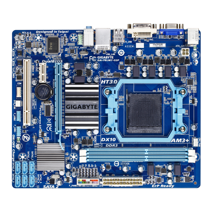
Page 5: Ga-78Lmt-Usb3/Ga-78Lmt-S2P Motherboard Layout
F_USB2 F_USB1 CLR_CMOS SYS_FAN Box Contents GA-78LMT-USB3 or GA-78LMT-S2P motherboard Motherboard driver disk Two SATA cables User's Manual I/O Shield * The box contents above are for reference only and the actual items shall depend on the product package you obtain. -
Page 6: Ga-78Lmt-Usb3/Ga-78Lmt-S2P Motherboard Block Diagram
GA-78LMT-USB3/GA-78LMT-S2P Motherboard Block Diagram CPU CLK+/- (200 MHz) 1 PCI Express x16 AM3+/AM3 CPU DDR3 1333+ (O.C.)/1066/800 MHz Dual Channel Memory 2 USB 3.0/2.0 j PCIe CLK Hyper Transport 3.0 RJ45 (100 MHz) Realtek Etron RTL8111E EJ168 j GFX CLK (100 MHz) -
Page 7: Chapter 1 Hardware Installation
Chapter 1 Hardware Installation Installation Precautions The motherboard contains numerous delicate electronic circuits and components which can become damaged as a result of electrostatic discharge (ESD). Prior to installation, carefully read the user's manual and follow these procedures: Prior to installation, do not remove or break motherboard S/N (Serial Number) sticker or •... -
Page 8: Product Specifications
Up to 8 USB 2.0/1.1 ports (4 on the back panel, 4 via the USB brackets connected to the internal USB headers) k Etron EJ168 chip: Š Up to 2 USB 3.0/2.0 ports on the back panel j Only for GA-78LMT-USB3. k Only for GA-78LMT-S2P. Hardware Installation - 8 -... - Page 9 Support for Xpress Install Š Support for Xpress Recovery2 Š Support for EasyTune Š * Available functions in EasyTune may differ by motherboard model. Support for Smart Recovery Š j Only for GA-78LMT-USB3. k Only for GA-78LMT-S2P. - 9 - Hardware Installation...
-
Page 10: Installing The Cpu And Cpu Cooler
Unique Features Support for Auto Green Š Support for ON/OFF Charge Š Support for Cloud OC Š Support for Q-Share Š Bundled Norton Internet Security (OEM version) Š Software Operating Support for Microsoft Windows 7/Vista/XP Š ® System Form Factor Micro ATX Form Factor;... -
Page 11: Installing The Memory
Installing the Memory Read the following guidelines before you begin to install the memory: Make sure that the motherboard supports the memory. It is recommended that memory of the • same capacity, brand, speed, and chips be used. (Go to GIGABYTE's website for the latest supported memory speeds and memory modules.) Always turn off the computer and unplug the power cord from the power outlet before installing •... -
Page 12: Back Panel Connectors
When removing the cable, pull it straight out from the connector. Do not rock it side to side to • prevent an electrical short inside the cable connector. (Note) The DVI-D port does not support D-Sub connection by adapter. j Only for GA-78LMT-USB3. k Only for GA-78LMT-S2P. Hardware Installation - 12 -... -
Page 13: Internal Connectors
Internal Connectors ATX_12V F_AUDIO F_USB1/F_USB2 CPU_FAN SYS_FAN CLR_CMOS SATA2_0/1/2/3/4/5 F_PANEL Read the following guidelines before connecting external devices: First make sure your devices are compliant with the connectors you wish to connect. • Before installing the devices, be sure to turn off the devices and your computer. Unplug the •... - Page 14 1/2) ATX_12V/ATX (2x2 12V Power Connector and 2x12 Main Power Connector) With the use of the power connector, the power supply can supply enough stable power to all the com- ponents on the motherboard. Before connecting the power connector, first make sure the power supply is turned off and all devices are properly installed.
-
Page 15: Fan Headers
3/4) CPU_FAN/SYS_FAN (Fan Headers) The motherboard has a 4-pin CPU fan header (CPU_FAN), a 3-pin system fan header (SYS_FAN). Most fan headers possess a foolproof insertion design. When connecting a fan cable, be sure to connect it in the correct orientation (the black connector wire is the ground wire). The motherboard supports CPU fan speed control, which requires the use of a CPU fan with fan speed control design. -
Page 16: F_Panel (Front Panel Header)
6) F_PANEL (Front Panel Header) Connect the power switch, reset switch, speaker, chassis intrusion switch/sensor and system status indicator on the chassis to this header according to the pin assignments below. Note the positive and negative pins before connecting the cables. SPEAK- PWR- Power LED... -
Page 17: Front Panel Audio Header
7) F_AUDIO (Front Panel Audio Header) The front panel audio header supports Intel High Definition audio (HD) and AC'97 audio. You may connect your chassis front panel audio module to this header. Make sure the wire assignments of the module con- nector match the pin assignments of the motherboard header. - Page 18 9) COM (Serial Port Header) The COM header can provide one serial port via an optional COM port cable. For purchasing the op- tional COM port cable, please contact the local dealer. Pin No. Definition NDCD- NSIN NSOUT NDTR- NDSR- NRTS- NCTS- NRI-...
-
Page 19: Battery
11) BAT (Battery) The battery provides power to keep the values (such as BIOS configurations, date, and time information) in the CMOS when the computer is turned off. Replace the battery when the battery voltage drops to a low level, or the CMOS values may not be accurate or may be lost. You may clear the CMOS values by removing the battery: Turn off your computer and unplug the power cord. -
Page 20: Chapter 2 Bios Setup
Chapter 2 BIOS Setup To access the BIOS Setup program, press the <Delete> key during the POST when the power is turned on. To see more advanced BIOS Setup menu options, you can press <Ctrl> + <F1> in the main menu of the BIOS Setup program. -
Page 21: The Main Menu
The Main Menu Once you enter the BIOS Setup program, the Main Menu (as shown below) appears on the screen. Use ar- row keys to move among the items and press <Enter> to accept or enter a sub-menu. (Sample BIOS Version: GA-78LMT-USB3 D13) CMOS Setup Utility-Copyright (C) 1984-2011 Award Software MB Intelligent Tweaker(M.I.T.) Load Fail-Safe Defaults... -
Page 22: Mb Intelligent Tweaker(M.i.t.)
MB Intelligent Tweaker(M.I.T.) CMOS Setup Utility-Copyright (C) 1984-2011 Award Software MB Intelligent Tweaker(M.I.T.) Item Help IGX Configuration [Press Enter] Menu Level CPU Clock Ratio [Auto] 2800Mhz CPU NorthBridge Freq. [Auto] 2000Mhz Core Performance Boost (Note) [Enabled] CPB Ratio [Auto] 3100Mhz (Note) Turbo CPB [Disabled] (Note) CPU Host Clock Control [Auto]... - Page 23 Surround View Enables or disables the Surround View function. This option is configurable only when Init Display First under Advanced BIOS Features is set to PEG and an ATI graphics card is installed. (Default: Disabled) VGA Core Clock control Allows you to determine whether to manually set the VGA Core clock. (Default: Auto) VGA Core Clock(MHz) Allows you to manually set the VGA Core clock.
- Page 24 Memory Clock This option is configurable only when Set Memory Clock is set to Manual. X4.00 Sets Memory Clock to X4.00. X5.33 Sets Memory Clock to X5.33. X6.66 Sets Memory Clock to X6.66. X8.00 Sets Memory Clock to X8.00. DRAM Configuration CMOS Setup Utility-Copyright (C) 1984-2011 Award Software DRAM Configuration Item Help...
- Page 25 Trfc1 for DIMM2 Options are: Auto (default), 90ns, 110ns, 160ns, 300ns, 350ns. Write Recovery Time Options are: Auto (default), 5T~8T, 10T, 12T. Precharge Time Options are: Auto (default), 4T~7T. Row Cycle Time Options are: Auto (default), 11T~42T. RAS to RAS Delay Options are: Auto (default), 4T~7T.
-
Page 26: Standard Cmos Features
CPU Voltage Control Allows you to set the CPU voltage. Auto sets the CPU voltage as required. The adjustable range is de- pendent on the CPU being installed. (Default: Normal) Note: Increasing CPU voltage may result in damage to your CPU or reduce the useful life of the CPU. Normal CPU Vcore Displays the normal operating voltage of your CPU. -
Page 27: Advanced Bios Features
The following fields display your hard drive specifications. If you wish to enter the parameters manually, refer to the information on the hard drive. Capacity Approximate capacity of the currently installed hard drive. Halt On Allows you to determine whether the system will stop for an error during the POST. Options are: "All Errors,"... - Page 28 AMD K8 Cool&Quiet control Auto Lets the AMD Cool'n'Quiet driver dynamically adjust the CPU clock and VID to re- duce heat output from your computer and its power consumption. (Default) Disabled Disables this function. CPU Unlock (Note) Allows you to determine whether unlock hidden CPU cores. (Default: Disabled) CPU core Control Allows you to determine whether to manually enable/disable CPU Core 1/2/3/4/5.
-
Page 29: Integrated Peripherals
Full Screen LOGO Show Allows you to determine whether to display the GIGABYTE Logo at system startup. Disabled displays normal POST message. (Default: Enabled) Backup BIOS Image to HDD Allows the system to copy the BIOS image file to the hard drive. If the system BIOS is corrupted, it will be recovered from this image file. - Page 30 OnChip SATA Port as ESP CMOS Setup Utility-Copyright (C) 1984-2011 Award Software OnChip SATA Port as ESP Item Help Port0 as ESP [Disabled] Menu Level Port1 as ESP [Disabled] Port2 as ESP [Disabled] Port3 as ESP [Disabled] x Port4 as ESP Disabled x Port5 as ESP Disabled : Move Enter: Select +/-/PU/PD: Value F10: Save ESC: Exit F1: General Help...
-
Page 31: Power Management Setup
Onboard USB 3.0 Controller (Etron EJ168 USB Controller) j Enables or disables the Etron EJ168 USB controller. (Default: Enabled) USB Controllers Enables or disables the integrated USB controllers. (Default: Enabled) Disabled will turn off all of the USB functionalities below. USB Legacy Function Allows USB keyboard to be used in MS-DOS. - Page 32 USB Wake Up from S3 Allows the system to be awakened from ACPI S3 sleep state by a wake-up signal from the installed USB device. (Default: Enabled) Modem Ring Resume Allows the system to be awakened from an ACPI sleep state by a wake-up signal from a modem that supports wake-up function.
-
Page 33: Pnp/Pci Configurations
ErP Support Determines whether to let the system consume less than 1W power in S5 (shutdown) state. (Default: Disabled) Note: When this item is set to Enabled, the following four functions will become unavailable: PME event wake up, power on by mouse, power on by keyboard, and wake on LAN. 2-8 PnP/PCI Configurations CMOS Setup Utility-Copyright (C) 1984-2011 Award Software PnP/PCI Configurations... -
Page 34: Load Fail-Safe Defaults
Current Voltage(V) Vcore/DDR3 1.5V/+3.3V/+12V Displays the current system voltages. Current System/CPU Temperature Displays current system/CPU temperature. Current CPU/SYSTEM FAN Speed (RPM) Displays current CPU/system fan speed. CPU Warning Temperature Sets the warning threshold for CPU temperature. When CPU temperature exceeds the threshold, BIOS will emit warning sound. -
Page 35: Load Optimized Defaults
2-11 Load Optimized Defaults CMOS Setup Utility-Copyright (C) 1984-2011 Award Software MB Intelligent Tweaker(M.I.T.) Load Fail-Safe Defaults Standard CMOS Features Load Optimized Defaults Advanced BIOS Features Set Supervisor Password Integrated Peripherals Set User Password Power Management Setup Save &... -
Page 36: Save & Exit Setup
2-13 Save & Exit Setup CMOS Setup Utility-Copyright (C) 1984-2011 Award Software MB Intelligent Tweaker(M.I.T.) Load Fail-Safe Defaults Standard CMOS Features Load Optimized Defaults Advanced BIOS Features Set Supervisor Password Save to CMOS and EXIT (Y/N)? Y Integrated Peripherals Set User Password ... -
Page 37: Chapter 3 Drivers Installation
Chapter 3 Drivers Installation • Before installing the drivers, first install the operating system. • After installing the operating system, insert the motherboard driver disk into your optical drive. The driver Autorun screen is automatically displayed which looks like that shown in the screen shot below. - Page 38 Steps: 1. Turn on your computer and press <Delete> to enter BIOS Setup during the POST (Power-On Self-Test). Ensure OnChip SATA Controller is enabled under Integrated Peripherals. To enable RAID for the SATA2_0/1/2/3 connectors, set OnChip SATA Type to RAID. To enable RAID for the SATA2_4/5 connec- tors, set OnChip SATA Type to RAID and set OnChip SATA Port4/5 Type to As SATA Type.
-
Page 39: Making A Sata Raid Driver Diskette
Making a SATA RAID Driver Diskette Copy the driver for the SATA controller from the motherboard driver disk to a floppy disk (for Windows XP) or a USB flash drive (for Windows 7/Vista). For example, to copy the RAID driver for Windows XP 32-bit operat- ing system, copy the driver from the following directory to your floppy disk: \BootDrv\SBxxx\x86. - Page 40 Appendix - 40 -...
- Page 41 - 41 - Appendix...
- Page 42 Appendix - 42 -...
- Page 43 - 43 - Appendix...
- Page 44 Contact Us GIGA-BYTE TECHNOLOGY CO., LTD. Address: No.6, Bao Chiang Road, Hsin-Tien Dist., New Taipei City 231,Taiwan TEL: +886-2-8912-4000, FAX: +886-2-8912-4003 Tech. and Non-Tech. Support (Sales/Marketing) : http://ggts.gigabyte.com.tw WEB address (English): http://www.gigabyte.com WEB address (Chinese): http://www.gigabyte.tw You may go to the GIGABYTE website, select your language in the language list on the top right corner of the website. • GIGABYTE Global Service System To submit a technical or non-technical (Sales/Market- ing) question, please link to:...