Table of Contents
Advertisement
GA-8I865GME-775-RH
Intel
Pentium
®
®
User's Manual
Rev. 1001
12ME-865GMETR-1001R
* The WEEE marking on the product indicates this product must not be disposed of with user's other household waste
and must be handed over to a designated collection point for the recycling of waste electrical and electronic equipment!!
* The WEEE marking applies only in European Union's member states.
4 LGA775 Processor Motherboard
Advertisement
Table of Contents

Related Manuals for Gigabyte GA-8I865GME-775-RH

Summary of Contents for Gigabyte GA-8I865GME-775-RH
- Page 1 GA-8I865GME-775-RH Intel Pentium 4 LGA775 Processor Motherboard ® ® User's Manual Rev. 1001 12ME-865GMETR-1001R * The WEEE marking on the product indicates this product must not be disposed of with user's other household waste and must be handed over to a designated collection point for the recycling of waste electrical and electronic equipment!!
- Page 3 Gigabyte's prior written permission. Specifications and features are subject to change without prior notice. Product Manual Classification In order to assist in the use of this product, Gigabyte has categorized the user manual in the following: For detailed product information and specifications, please carefully read the "User’s Manual."...
-
Page 4: Table Of Contents
Table of Contents Item Checklist ......................... 6 Optional Accessories ...................... 6 GA-8I865GME-775-RH Motherboard Layout ..............7 Block Diagram ........................ 8 Chapter 1 Hardware Installation ..................9 Considerations Prior to Installation ..............9 Feature Summary ..................10 Installation of the CPU and Heatsink .............. 12 1-3-1 Installation of the CPU .................. - Page 5 Chapter 3 Drivers Installation ..................47 Install Chipset Drivers ..................47 Software Applications ..................48 Driver CD Information ..................48 Hardware Information ..................49 Contact Us ..................... 49 Chapter 4 Appendix ....................51 Unique Software Utilities ................51 4-1-1 EasyTune 5 Introduction ..................52 4-1-2 Xpress Recovery2 Introduction .................
-
Page 6: Item Checklist
Item Checklist IDE Cable x 1 Serial ATA Cable x 1 I/O Shield * The items listed above are for reference only, and are subject to change without notice. Optional Accessories 2 Ports USB2.0 Cable (Part Number: 12CR1-1UB030-51) - 6 -... -
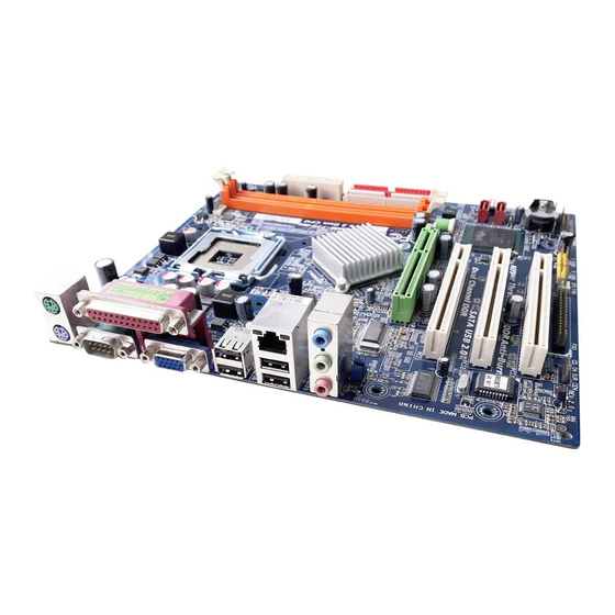
Page 7: Ga-8I865Gme-775-Rh Motherboard Layout
GA-8I865GME-775-RH Motherboard Layout ATX_12V KB_MS LGA775 CPU_FAN R_USB IT8712 Intel 865G USB_LAN AUDIO F_AUDIO SATA1 EP82562G PCI1 ICH5 SATA0 PCI2 PCI3 CODEC BIOS F_USB1 PWR_LED CD_IN SYS _FAN F_PANEL - 7 -... -
Page 8: Block Diagram
Block Diagram CPUCLK+/-(133/200MHz) LGA775 Processor Host Interface DDR 400/333/266MHz DIMM AGP 8X/4X Dual Channel Memory Intel 865G HCLK (133/200MHz) AGPCLK GMCH (66MHz) GMCHCLK (66MHz) 66MHz 33MHz 14.318MHz 48MHz BIOS PCI Bus 2 Serial ATA Intel ICH5 ATA33/66/100 EP82562G IDE Channels Floppy RJ45 LPT Port... -
Page 9: Chapter 1 Hardware Installation
2. Damage as a result of violating the conditions recommended in the user manual. 3. Damage due to improper installation. 4. Damage due to use of uncertified components. 5. Damage due to use exceeding the permitted parameters. 6. Product determined to be an unofficial Gigabyte product. - 9 - Hardware Installation... -
Page 10: Feature Summary
1 PS/2 keyboard port 1 PS/2 mouse port 1 parallel port 1 serial port (COMA) 1 VGA port 4 USB 2.0/1.1 ports 1 RJ-45 port 3 audio jacks (Line In / Line Out / MIC In) GA-8I865GME-775-RH Motherboard - 10 -... - Page 11 Norton Internet Security (OEM version) Form Factor Micro ATX form factor; 24.4cm x 21.2cm (Note 1) For further CPU support information, please go to GIGABYTE's website. (Note 2) EasyTune functions may vary depending on different motherboards. - 11 - Hardware Installation...
-
Page 12: Installation Of The Cpu And Heatsink
(Grasping the CPU firmly between your thumb and forefinger, carefully place it into the socket in a straight and downwards motion. Avoid twisting or bending motions that might cause damage to the CPU during installation.) GA-8I865GME-775-RH Motherboard - 12 -... -
Page 13: Installation Of The Heatsink
1-3-2 Installation of the Heatsink Male Push Pin The top of Female Push Pin Female Push Pin Fig. 2 Fig.1 (Turning the push pin along the direction of arrow Please apply an even layer of heatsink paste on is to remove the heatsink, on the contrary, is to the surface of the installed CPU. -
Page 14: Installation Of Memory
DIMM socket. Then push it down. Fig. 1 Fig.2 Close the plastic clip at both edges of the DIMM sockets to lock the DIMM module. Reverse the installation steps when you wish to remove the DIMM module. Fig. 2 GA-8I865GME-775-RH Motherboard - 14 -... -
Page 15: Installation Of Expansion Cards
Installation of Expansion Cards You can install your expansion card by following the steps outlined below: 1. Read the related expansion card's instruction document before installing the expansion card into the computer. 2. Remove your computer's chassis cover, screws and slot bracket from the computer. 3. -
Page 16: I/O Back Panel Introduction
Line Out (Front Speaker Out) Connect the stereo speakers, earphone or front surround speakers to this connector. MIC In Microphone can be connected to MIC In jack. You can use audio software to configure 2-/4-/6- channel audio functioning. GA-8I865GME-775-RH Motherboard - 16 -... -
Page 17: Connectors Introduction
Connectors Introduction ATX_12V PWR_LED ATX (Power Connector) F_AUDIO CPU_FAN CD_IN SYS_FAN F_USB1 IDE1 / IDE2 CLR_CMOS SATA0 / SATA1 F_PANEL - 17 - Hardware Installation... - Page 18 Pin No. Definition +12V +12V Pin No. Definition 3.3V 3.3V Power Good 5V SB (stand by +5V) +12V 3.3V -12V PS_ON(soft on/off) GA-8I865GME-775-RH Motherboard - 18 -...
- Page 19 3/4) CPU_FAN / SYS_FAN (Cooler Fan Power Connector) The cooler fan power connector supplies a +12V power voltage via a 3-pin/4-pin (only for CPU_FAN) power connector and possesses a fool-proof connection design. Most coolers are designed with color-coded power connector wires. A red power connector wire indicates a positive connection and requires a +12V power voltage.
- Page 20 7) SATA0/SATA1 (Serial ATA Connector,) Serial ATA can provide up to 150MB/s transfer rate. Please refer to the BIOS setting for the Serial ATA and install the proper driver in order to work properly. Pin No. Definition GA-8I865GME-775-RH Motherboard - 20 -...
-
Page 21: F_Panel (Front Panel Connector)
8) F_PANEL (Front Panel Connector) Please connect the power LED, PC speaker, reset switch and power switch etc. of your chassis front panel to the F_PANEL connector according to the pin assignments below. Speaker Connector Message LED/ Power Power/ Switch Sleep LED Reset Switch IDE Hard Disk Active LED... - Page 22 Pin No. Definition MIC_BIAS POWER FrontAudio(R) Rear Audio (R)/ Return R No Pin FrontAudio (L) Rear Audio (L)/ Return L GA-8I865GME-775-RH Motherboard - 22 -...
- Page 23 11) CD_IN (CD IN Connector) Connect CD-ROM or DVD-ROM audio out to the connector. Pin No. Definition CD-L CD-R 12) F_USB1 (Front USB Connectors) Be careful with the polarity of the front USB connector. Check the pin assignment carefully while you connect the front USB cable, incorrect connection between the cable and connector will make the device unable to work or even damage it.
- Page 24 You may clear the CMOS data to its default values by this jumper. To clear CMOS, temporarily short pins 1-2. To prevent improper use of this header, we do not include a jumper on it. Open: Normal Short: Clear CMOS GA-8I865GME-775-RH Motherboard - 24 -...
-
Page 25: Hardware Installation
15) BAT (Battery) Danger of explosion if battery is incorrectly replaced. Replace only with the same or equivalent type recommended by the manufacturer. Dispose of used batteries according to the manufacturer's instructions. If you want to erase CMOS... 1. Turn OFF the computer and unplug the power cord. 2. - Page 26 GA-8I865GME-775-RH Motherboard - 26 -...
-
Page 27: Chapter 2 Bios Setup
BIOS needs to be reset to its original settings. If you wish to upgrade to a new BIOS, either GIGABYTE's Q-Flash or @BIOS utility can be used. Q-Flash allows the user to quickly and easily update or backup BIOS without entering the operating system. -
Page 28: The Main Menu (For Example: Bios Ver. : E1)
<F12> : For Boot Menu Select boot sequence for onboard (or add-on cards) device. Award Modular BIOS v6.00PG, An Energy Star Ally Copyright (C) 1984-2006, Award Software, Inc. GA-8I865GME-775-RH E1 <F12> For Boot Menu <DEL>:BIOS Setup/Q-Flash, <F9>: Xpress Recovery2, <F12>For Boot Menu 03/21/2006-i865G-6A79AG0UC-00 Use <... - Page 29 Standard CMOS Features This setup page includes all the items in standard compatible BIOS. Advanced BIOS Features This setup page includes all the items of Award special enhanced features. Integrated Peripherals This setup page includes all onboard peripherals. Power Management Setup This setup page includes all the items of Green function features.
-
Page 30: Standard Cmos Features
Select this if no IDE devices are used and the system will skip the automatic detection step and allow for faster system start up. Access Mode Use this to set the access mode for the hard drive. The two options are: Large/Auto(default:Auto) GA-8I865GME-775-RH Motherboard - 30 -... - Page 31 Capacity Capacity of currently installed hard drive. Hard drive information should be labeled on the outside drive casing. Enter the appropriate option based on this information. Cylinder Number of cylinders Head Number of heads Precomp Write precomp Landing Zone Landing zone Sector Number of sectors Drive A / Drive B...
-
Page 32: Advanced Bios Features
The system will boot, but access to Setup will be denied if the correct password is not entered at the prompt. (Default value) (Note) This item will show up when you install a processor that supports this function. GA-8I865GME-775-RH Motherboard - 32 -... - Page 33 CPU Hyper-Threading Enabled Enables CPU Hyper Threading Feature. Please note that this feature is only working for operating system with multi processors mode supported. (Default value) Disabled Disables CPU Hyper Threading. Limit CPUID Max. to 3 Enabled Limit CPUID Maximum value to 3 when use older OS like NT4. Disabled Disables CPUID Limit for windows XP.
-
Page 34: Integrated Peripherals
Windows XP or later. (Default value) SATA Port1 Set SATA controller to native mode(Serial ATA mode - SATA Port 1). This mode is only supported by Windows XP or later. GA-8I865GME-775-RH Motherboard - 34 -... - Page 35 SATA Port1 configure as The setting depends on "SATA Port0 configure as" item setting. (Default: SATA Port1) USB Controller Enabled Enable USB controller. (Default value) Disabled Disable USB controller. USB 2.0 Controller You can disable this function if you are not using onboard USB 2.0 feature. Enabled Enable USB 2.0 controller.
- Page 36 Using Parallel port as Extended Capabilities Port. ECP+EPP Using Parallel port as ECP and EPP mode. ECP Mode Use DMA Set ECP Mode Use DMA to 3. (Default value) Set ECP Mode Use DMA to 1. GA-8I865GME-775-RH Motherboard - 36 -...
-
Page 37: Power Management Setup
Power Management Setup CMOS Setup Utility-Copyright (C) 1984-2006 Award Software Power Management Setup ACPI Suspend Type [S1(POS)] Item Help Power LED in S1 state [Blinking] Menu Level Off by Power button [Instant-off] PME Event Wake Up [Enabled] ModemRingOn/WakeOnLan [Enabled] Resume by Alarm [Disabled] x Date (of Month) Alarm Everday... - Page 38 Input password(from 1 to 5 characters) and press Enter to set the password. AC BACK Function Soft-Off When AC-power back to the system, the system will be in "Off" state. (Default value) Full-On When AC-power back to the system, the system always in "On" state. GA-8I865GME-775-RH Motherboard - 38 -...
-
Page 39: Pnp/Pci Configurations
PnP/PCI Configurations CMOS Setup Utility-Copyright (C) 1984-2006 Award Software PnP/PCI Configurations PCI1 IRQ Assignment [Auto] Item Help PCI2 IRQ Assignment [Auto] Menu Level PCI3 IRQ Assignment [Auto] Device(s) using this INT: : Move Enter: Select +/-/PU/PD: Value F10: Save ESC: Exit F1: General Help F5: Previous Values F6: Fail-Safe Default... -
Page 40: Pc Health Status
C / 176 C / 194 Monitor CPU temperature at 90 C / 194 Disabled Disable this function. (Default value) CPU/SYSTEM FAN Fail Warning Disabled Fan warning function disable. (Default value) Enabled Fan warning function enable. GA-8I865GME-775-RH Motherboard - 40 -... - Page 41 CPU Smart FAN Control Disabled Disable this function. Enabled When this function is enabled, CPU fan will run at different speed depending on CPU temperature. Users can adjust the fan speed with Easy Tune based on their requirements. (Default Value) CPU Smart FAN Mode This option is available only when CPU Smart FAN Control is enabled.
-
Page 42: Frequency/Voltage Control
Set Memory frequency by DRAM SPD data. (Default value) Memory Frequency (Mhz) The values depend on "CPU Host Frequency(Mhz)" item. (Note) This item will show up when you install a processor which supports this function. GA-8I865GME-775-RH Motherboard - 42 -... -
Page 43: Load Fail-Safe Defaults
Load Fail-Safe Defaults CMOS Setup Utility-Copyright (C) 1984-2006 Award Software Standard CMOS Features Load Fail-Safe Defaults Advanced BIOS Features Load Optimized Defaults Integrated Peripherals Set Supervisor Password Power Management Setup Set User Password Load Fail-Safe Defaults (Y/N)? N PnP/PCI Configurations Save &... -
Page 44: Set Supervisor/User Password
Setup Menu. If you select "Setup" at "Password Check" in Advance BIOS Features Menu, you will be prompted only when you try to enter Setup. GA-8I865GME-775-RH Motherboard - 44 -... -
Page 45: Save & Exit Setup
2-11 Save & Exit Setup CMOS Setup Utility-Copyright (C) 1984-2006 Award Software Standard CMOS Features Load Fail-Safe Defaults Advanced BIOS Features Load Optimized Defaults Integrated Peripherals Set Supervisor Password Power Management Setup Set User Password PnP/PCI Configurations Save & Exit Setup PC Health Status Save to CMOS and EXIT (Y/N)? Y Exit Without Saving... - Page 46 GA-8I865GME-775-RH Motherboard - 46 -...
-
Page 47: Chapter 3 Drivers Installation
Chapter 3 Drivers Installation Pictures below are shown in Windows XP. (1) Please make sure to install the latest service pack for Windows after OS installation and before installing motherboard drivers. (2) Insert the driver CD that came with your motherboard into your CD-ROM drive, the driver CD will auto start and installation screen will appear. -
Page 48: Software Applications
Software Applications This page displays all the tools that Gigabyte developed and some free software. You can click an item to install it. Driver CD Information This page lists the contents of software and drivers in this CD-title. GA-8I865GME-775-RH Motherboard... -
Page 49: Hardware Information
Hardware Information This page lists all device you have for this motherboard. Contact Us You can also see the last page of this manual for contacts information details. - 49 - Drivers Installation... - Page 50 GA-8I865GME-775-RH Motherboard - 50 -...
-
Page 51: Chapter 4 Appendix
Motherboard Intelligent Tweaker (M.I.T.) allows user to access and change BIOS feature settings with relative speed and ease. Through GIGABYTE M.I.T. feature the user is no longer required to switch into different modes within BIOS setup in order to change system settings such as the CPU system bus, memory timings or to enabled Gigabyte's unique C.I.A. -
Page 52: Easytune 5 Introduction
Toggles between Easy and Advance Mode Display screen Display panel of CPU frequency Function display LEDs Shows the current functions status GIGABYTE Logo Log on to GIGABYTE website Help button Display EasyTune 5 Help file Exit or Minimize button Quit or Minimize EasyTune... -
Page 53: Xpress Recovery2 Introduction
4-1-2 Xpress Recovery2 Introduction Xpress Recovery2 is designed to provide quick backup and restora- tion of hard disk data. Supporting Microsoft operating systems including Windows XP/2000/NT/98/Me and DOS, and file systems including FAT16, FAT32, and NTFS, Xpress Recovery2 is able to back up data on hard disks on PATA and SATA IDE controllers. - Page 54 (As this is a BIOS-related issue, it can be solved by BIOS update) GA-K8NXP-9 GA-8N-SLI Royal GA-K8U GA-K8N Ultra-9 GA-8N-SLI Pro GA-K8U-9 GA-K8NF-9 (PCB Ver. 1.0) GA-8N-SLI GA-K8NXP-SLI GA-K8NE (PCB Ver. 1.0) GA-K8N Ultra-SLI GA-K8NMF-9 GA-K8N Pro-SLI GA-8I865GME-775-RH Motherboard - 54 -...
-
Page 55: Flash Bios Method Introduction
Updating BIOS with Q-Flash Utility on Dual BIOS Motherboards. Some of Gigabyte motherboards are equipped with dual BIOS. In the BIOS menu of the motherboards supporting Q-Flash and Dual BIOS, the Q-Flash utility and Dual BIOS utility are combined in the same screen. - Page 56 Contains the names of four tasks. Blocking a task and pressing Enter key on your keyboard to enable execu- tion of the task. Action bar: Contains the names of four actions needed to operate the Q-Flash/Dual BIOS utility. Pressing the buttons mentioned on your keyboards to perform these actions. GA-8I865GME-775-RH Motherboard - 56 -...
- Page 57 Using the Q-Flash utility: This section tells you how to update BIOS using the Q-Flash utility. As described in the "Before you begin" section above, you must prepare a floppy disk having the BIOS file for your motherboard and insert it to your computer.
- Page 58 Primary Master : FUJITSU MPE3170AT ED-03-08 Primary Slave : None Secondary Master : CREATIVEDVD-RM DVD1242E BC101 Secondary Slave : None Press DEL to enter SETUP / Dual BIOS / Q-Flash / F9 For Xpress Recovery 09/23/2003-i875P-6A79BG03C-00 GA-8I865GME-775-RH Motherboard - 58 -...
-
Page 59: Updating Bios With Q-Flash Utility On Single-Bios Motherboards
6. Press Del to enter BIOS menu after system reboots. When you are in BIOS menu, move to Load Optimized Defaults item and press Enter to load BIOS Optimized Defaults. Normally the system redetects all devices after BIOS has been upgraded. Therefore, we highly recommend reloading the BIOS defaults after BIOS has been upgraded. - Page 60 ESC:Reset F10:Power Off After BIOS file is read, you'll see a confirmation dialog box asking you "Are you sure to update BIOS?" Please do not take out the floppy disk when it begins flashing BIOS. GA-8I865GME-775-RH Motherboard - 60 -...
- Page 61 Press Y button on your keyboard after you are sure to update BIOS. Then it will begin to update BIOS. The progress of updating BIOS will be shown at the same time. Q-Flash Utility V1.30 Flash Type/Size.........SST 49LF003A 256K Keep DMI Data Enable Do not turn off power or Updating BIOS Now...
- Page 62 Windows. Just select the desired @BIOS server to download the latest version of BIOS. Fig 1. Installing the @BIOS utility Fig 2. Installation Complete and Run @BIOS Click Sart/ Programs/ GIGABYTE/@BIOS Select @BIOS item Fig 3. The @BIOS Utility Fig 4. Select the desired @BIOS server Click "...
- Page 63 III. In method I, if the BIOS file you need cannot be found in @BIOS server, please go onto Gigabyte's web site for downloading and updating it according to method II. IV. Please note that any interruption during updating will cause system unbooted.
-
Page 64: / 6 Channel Audio Function Introduction
Click the icon to select the function. STEP 3: On the AC97 Audio Configuration menu, click the Speaker Configuration tab and select the 2-channel mode for stereo speaker output check box. GA-8I865GME-775-RH Motherboard - 64 -... - Page 65 4 Channel Analog Audio Output Mode STEP 1: Connect the front channels to "Line Out," the rear channels to "Line In." Line Out Line In STEP 2: After installing the audio driver, you'll find a Sound Effect icon on the lower right hand taskbar. Click the icon to select the function.
- Page 66 5.1 speaker output check box. Clear the Only SURROUND-KIT check box and press When the Environment setting is None, the sound would be performed as stereo mode (2-channel output). Please select the other settings for 6 channels output. GA-8I865GME-775-RH Motherboard - 66 -...
-
Page 67: Troubleshooting
Below is a collection of general asked questions. To check general asked questions based on a specific motherboard model, please log on to http://www.gigabyte.com.tw Question 1: I cannot see some options that were included in previous BIOS after updating BIOS. Why? Answer: Some advanced options are hidden in new BIOS version. - Page 68 GA-8I865GME-775-RH Motherboard - 68 -...
- Page 69 - 69 - Appendix...
- Page 70 GA-8I865GME-775-RH Motherboard - 70 -...
- Page 71 Contact Us Taiwan (Headquarters) Japan GIGA-BYTE TECHNOLOGY CO., LTD. NIPPON GIGA-BYTE CORPORATION Address: No.6, Bau Chiang Road, Hsin-Tien, Taipei 231, WEB address : http://www.gigabyte.co.jp Taiwan Singapore TEL: +886-2-8912-4888 GIGA-BYTE SINGAPORE PTE. LTD. FAX: +886-2-8912-4003 Tech. Support : Tech. Support : http://www.gigabyte.com.tw/Support/ServiceCenter.aspx...
- Page 72 Tech. Support : Ltd. http://www.gigabyte.com.tw/Support/ServiceCenter.aspx Tech. Support : Non-Tech. Support(Sales/Marketing) : http://www.gigabyte.com.tw/Support/ServiceCenter.aspx http://ggts.gigabyte.com.tw/nontech.asp Non-Tech. Support(Sales/Marketing) : WEB address : http://www.gigabyte.com.cn http://ggts.gigabyte.com.tw/nontech.asp Shanghai WEB address : http://www.gigabyte.ru TEL: +86-021-63410999 Poland FAX: +86-021-63410100 Office of GIGA-BYTE TECHNOLOGY Co., Ltd. in POLAND Beijing Tech.