Yamaha AW4416 Operation Manual
Professional audio workstation
Hide thumbs
Also See for AW4416:
- Operation manual (280 pages) ,
- Reference manual (191 pages) ,
- Service manual (154 pages)
Table of Contents
Advertisement
Quick Links
Advertisement
Chapters
Table of Contents

Related Manuals for Yamaha AW4416


Summary of Contents for Yamaha AW4416
- Page 2 PROFESSIONAL AUDIO WORKSTATION Operation Guide...
- Page 3 300 ohm ribbon lead, change the lead-in to coaxial type cable. If these corrective measures do not produce satisfactory results, please contact the local retailer authorized to distribute this type of product. If you can not locate the appropriate retailer, please contact Yamaha Corporation of America, Electronic Service Division, 6600 Orangethorpe Ave, Buena Park, CA 90620 The above statements apply ONLY to those products distributed by Yamaha Corporation of America or its subsidiaries.
- Page 4 For the removal of the battery at the moment of the batterij op het moment dat u het apparaat ann het einde disposal at the end of the service life please consult your van de levensduur afdankt of de volgende Yamaha Service retailer or Yamaha Service Center as follows: Afdeiing:...
- Page 5 Important Important Read the following before operating the AW4416 Warnings • Do not allow water to enter this unit or allow the unit to become wet. Fire or electrical shock may result. • Connect this unit’s power cord only to an AC outlet of the type stated in this Owner’s Manual or as marked on the unit.
- Page 6 Important • Do not touch the power plug with wet hands. Doing so is a potential electri- cal shock hazard. • Use only the included power supply cable for this unit. Using other types may be a fire hazard. • Always touch a well-grounded metal surface or the like to fully discharge any static electric charge on your body and clothing before handling an I/O card or hard disk.
- Page 7 CD-R media, regardless of whether such loss could have been or actually was foreseen by Yamaha. • Nor does Yamaha guarantee the media against any defect that may render it unusable.
- Page 8 Important Warning The Yamaha Professional Audio Workstation is designed to be used professionally and responsibly by recording industry professionals. The reproduction, distribu- tion, or, in some instances, the public performance, of all or a portion of a sound recording or musical composition protected by copyright, without having obtained a proper license from the relevant copyright holders, may constitute copyright infringement and may otherwise violate copyright laws and other laws.
-
Page 9: Table Of Contents
Turning the power off ........17 Transporting the AW4416 ....... . 18 Vibration during use . - Page 10 Chapter 1 Welcome to the world of the AW4416 ..19 Features of the AW4416 ....... . . 19 Mixer section .
- Page 11 Level meters/counter........54 Basic operation of the AW4416 ......56 Accessing a screen/page .
- Page 12 Table of contents Mixdown ..........95 Creating the mix balance of the tracks .
- Page 13 Chapter 9 Track and virtual track operations...147 The track structure of the AW4416......147 Switching virtual tracks .
- Page 14 Table of contents Inserting an effect into a desired channel ....171 Patching ..........171 Inserting an effect into monitor channel 1 .
- Page 15 ......... . . 240 Using MMC to control the AW4416 ..... . . 243 Chapter 16 Backing up and restoring songs .
-
Page 16: Before You Begin
Copyright No part of the AW4416 software or the manuals may be reproduced or distrib- uted in any form or by any means without the prior written authorization of Yamaha Corporation. -
Page 17: Installing An Internal Hard Disk
Before you begin Installing an internal hard disk You must install a hard disk in the AW4416 before using it. If you attempt to use the AW4416 without installing a hard disk, the recorder section and mixer sec- tion will fail to operate correctly, and the AW4416 will be damaged as well. -
Page 18: Installation
• Never attempt to disassemble a hard disk or apply excessive force to it. • The AW4416 is shipped with four screws for attaching a 2.5 inch hard disk, and four screws for attaching a CD-RW drive, making a total of eight included screws of the same type. - Page 19 If you fail to tighten the screws all the way, the hard disk may vibrate and fail to operate correctly. • Do not turn on the power of the AW4416 until all options have been installed. • When you turn on the power of the AW4416 after installing a new hard disk, formatting of the hard disk will begin automatically ( P.15).
-
Page 20: Installing A Cd-Rw Drive
Maximum 138 mm The SCSI ID of the CD-RW drive • The SCSI ID of the AW4416 itself is fixed at “6.” For this reason, you must set the SCSI ID of the CD-RW drive to “6” before installing it. -
Page 21: Installation Procedure
• Philips (+) screwdriver • Work surface • In order to install the CD-RW drive you will need to turn the AW4416 on its back. Make sure that you have a sufficiently broad work surface. • The AW4416 is shipped with four screws for attaching the 2.5 inch hard disk, and four screws for attaching the CD-RW drive, making a total of eight screws of the same type. - Page 22 AW4416. 6. Connect the red and white four-conductor cable included with the AW4416 to the internal connector of the AW4416 as shown in the dia- gram. Then connect the cable to the connector of the CD-RW drive. — Operation Guide...
- Page 23 CD-RW drive. 8. Align the screw holes in the bottom of the CD-RW drive with the screw holes of the AW4416, and use a screwdriver to fasten the drive with the four included screws. 9. Re-attach the CD-RW drive cover and the bottom panel that you removed in step 3.
-
Page 24: Removing The Transport Protection Pad
Be sure to save the transport protection pad for the next time you need to trans- port the unit. How to remove the transport protection pad 1. Install the CD-RW drive in the AW4416. 2. Turn on the power of the AW4416. Set the SCSI ID number as necessary ( P.259). -
Page 25: Manual Eject (Emergency Disc Removal)
The external SCSI devices referred to here are storage devices used to backup/ restore the internal data of the AW4416, and can be connected to the SCSI con- nector on the rear panel of the AW4416. The following types of storage device can be used. -
Page 26: Connection Procedure
• The SCSI ID of the AW4416 itself is fixed at “6. ” • In the various screens of the AW4416, the SCSI ID of the internal CD-RW drive has been set to “3” by default. For this reason, if you install a CD-RW drive, you will find it convenient to set its ID to “3. -
Page 27: About Terminators
SCSI cables, there may be cases in which better results are obtained by terminat- ing only one end of the chain. If problems occur such as the AW4416 failing to start up when an external SCSI device is connected, try defeating one of the ter- minators. -
Page 28: Installing I/O Cards
I/O cards compatible with the Yamaha mini-YGDAI format can be installed in the OPTION I/O slots 1/2 located on the rear panel of the AW4416 in order to add input/output ports. For example by installing an ADAT format compatible I/O card into an OPTION I/O slot, you can transmit/receive eight channels of digital audio to/from an ADAT format digital recorder. -
Page 29: Installation Procedure
Please carefully read the cautions for installing optional devices, given at the beginning of this manual. 1. Make sure that the power of the AW4416 is turned off. For safety’s sake, disconnect the power cable from the AC outlet. 2. From the OPTION I/O slot located on the rear panel of the AW4416, remove the two screws that hold the cover in place. -
Page 30: Important Points You Must Observe
You must use the following procedure to turn the power of the AW4416 on or off. Turning the power on To turn on the power of a system that includes the AW4416, you must turn on the power switches in the following order. -
Page 31: Setting The Internal Clock
Setting the internal clock When the AW4416 is shipped from the factory, its internal clock is set to Japan time. When you create a song on the AW4416, the song will store the date and time using this internal time. -
Page 32: Turning The Power Off
Important points you must observe Turning the power off To turn off the power of a system that includes the AW4416, you must turn off the power switches in the following order. 1 The monitor system connected to the output jacks of the AW4416 B The AW4416 itself C Storage devices connected to the AW4416’s SCSI connector, and external... -
Page 33: Transporting The Aw4416
• Even if the AW4416 is packed as described at the above, any damage or mal- functions that occur due to dropping the unit etc. may not be covered under warranty. -
Page 34: Chapter 1 Welcome To The World Of The Aw4416
flow. Features of the AW4416 The AW4416 is an audio workstation that combines a digital mixer, hard disk recorder, multi-effects, and sampling pads. It is the only equipment you need to perform the entire music production process, from multi-track recording, mixing, (*1) audio editing, effect processing, and creating a final CD... -
Page 35: Recorder Section
A hard disk attached to the ADP25H cartridge (sold separately) can be inserted into the hard disk slot of the AW4416, allowing you to exchange hard disks as easily and conveniently as if you were using removable media. -
Page 36: Sampling Pad Section
Other features Simple panel layout and efficient operation The AW4416 features a large backlit LCD and a three-color FL display, providing a graphic user interface that can be used intuitively and efficiently. A serial mouse (9 pin D-sub connector) can also be connected. - Page 37 Chapter1—Welcome to the world of the AW4416 Signal flow within the AW4416 The following diagram shows the general signal flow of the AW4416. As you can see from this diagram, the AW4416 consists of several sections: input patch, out- put patch, mixer, sampling pads, recorder, and CD-RW drive (optional).
-
Page 38: Input Patch
Chapter1—Welcome to the world of the AW4416 Input patch The input patch section is where input signals are assigned to input channels 1– 24 and return channels 1/2. The following types of input signal can be selected. MIC/LINE INPUT Input signals from analog INPUT jacks 1–8. -
Page 39: Input Channels 1-24
Chapter1—Welcome to the world of the AW4416 MIC/LINE INPUT PEAK INPUT INSERT INPUT 1-24 PEAK INPUT Hi-z 8 ch ONLY OPTION IN SLOT1 RETURN 1/2 SLOT2 SAMPLING EFFECT 1 EFFECT 2 DIGITAL STEREO IN METRONOME Input channels 1–24 There are monaural input channels used mainly for inputting mics or line level instruments. -
Page 40: Return Channels 1/2
Chapter1—Welcome to the world of the AW4416 Return channels 1/2 These are stereo input channels used mainly to input the return signals from inter- nal effects 1/2. However they can also be used as supplementary input channels by changing the input signal assignments of the input patch section. -
Page 41: Recorder Input Patching
Chapter1—Welcome to the world of the AW4416 Recorder input patching This section assigns the signals that are input to tracks 1–16 of the recorder sec- tion. The following types of signal can be selected. STEREO The stereo bus output signal that has passed through the stereo output channel. -
Page 42: Digital Cascade Connections
* For the signal flow diagram, refer to Oscillator, below. Oscillator The AW4416 has a built-in oscillator section that allows you to select a sine wave (100 Hz, 1 kHz, 10 kHz) or white noise. The signal of the oscillator can be output from one of the following buses: buses 1–8, AUX buses 1–8, or the stereo bus. -
Page 43: Aux Buses 1-8
HOME screen Bus page ([HOME] key [F3] key). Tip! When the AW4416 is in its default state, the output of AUX buses 7/8 is sent to the output patch section, and simultaneously assigned to the inputs of internal effects 1/ 2 as well. -
Page 44: Output Patch
METER Internal effects 1/2 When the AW4416 is in its default state, the output of AUX bus 7/8 is sent to the output patch section, and simultaneously assigned to the inputs of internal effects 1/2 as well. The outputs of effects 1/2 are respectively assigned to return channels 1/2. -
Page 45: Monitor Output/Headphone Output
RETURN 1/2 INSERT SEND Monitor output/headphone output As monitoring jacks, the AW4416 provides MONITOR OUT jacks and a PHONES jack. The types of signal that are output from these jacks will change as follows, depending on the state of the AW4416. -
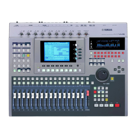
Page 46: Top Panel
Parts and their func- tions This chapter explains the names and functions of the various objects on the top panel, rear panel, and front panel. Note Names of the controllers on the top panel are enclosed in square brackets [ ], in order to distinguish them from the “software”... -
Page 47: Work Navigate Section
Chapter2—Parts and their functions D [MONITOR OUT] control This control adjusts the output level of the signal that is sent from the rear panel MONITOR OUT jacks. WORK NAVIGATE section PROFESSIONAL AUDIO WORKSTATION WORK NAVIGATE SONG QUICK MASTER- PLAY SHUT DOWN WORK NAVIGATE QUICK MASTER-... -
Page 48: Mixer Section
Chapter2—Parts and their functions B [FILE] key This key accesses the FILE screen, where you can backup/restore songs and for- mat external storage devices connected to the SCSI connector. C [UTILITY] key This key accesses the UTILITY screen, where you can operate the built-in oscilla- tor, and make various system settings. -
Page 49: Fader Mode Section
Chapter2—Parts and their functions FADER MODE section In this section you can select the items that will be controlled by faders 1–16 of the top panel. PROFESSIONAL AUDIO WORKSTATION FADER MODE FADER MODE EFF 1 EFF 2 HOME EFF 1 EFF 2 HOME 1 [HOME] key... -
Page 50: Mixing Layer Section
Chapter2—Parts and their functions MIXING LAYER section PROFESSIONAL AUDIO WORKSTATION MIXING LAYER 1-16 17-24 MONI INPUT INPUT RECORDER MIXING LAYER 17-24 1-16 MONI INPUT INPUT RECORDER 1 [1-16] key B [17-24] key C [MONI] key In this section you can select the mixing layer that will be controlled by the top panel [SEL] keys 1–16, [ON] keys 1–16 and faders 1–16. - Page 51 Chapter2—Parts and their functions Stereo output channel 17-24 Effect return channels 1/2 STEREO Input channels 17–24 No function The faders will not be operable. Attempting to move them by force will cause malfunctions. MONI STEREO Monitor channels 1–16 Stereo output channel The parameters controlled by faders 1–16 will also change depending on the set- tings of the FADER MODE section.
-
Page 52: [Sel] Keys, [On] Keys, Faders
Chapter2—Parts and their functions [SEL] keys, [ON] keys, faders PROFESSIONAL AUDIO WORKSTATION SOLO STEREO SOLO STEREO 1 [SEL] (select) keys These keys select the channel to be operated. The [SEL] key of the currently selected channel will light. When using automix, the [SEL] keys are used to select the channels that will be recorded. -
Page 53: Display Section
Chapter2—Parts and their functions Display section HIGH HI-MID LO-MID SHIFT SHIFT PROFESSIONAL AUDIO WORKSTATION HI-MID LO-MID SHIFT SHIFT 1 Display This is a 320 240 pixel liquid crystal display with backlight, that displays the val- ues of the mix parameters and the current operating status. B [PAN] control This controls the pan of the channel currently selected by the [SEL] key. -
Page 54: Level Meter/Counter Section
Chapter2—Parts and their functions F [SHIFT] key This key is used to switch the tabs or buttons shown at the bottom of the display. You can use a variety of additional functions by holding down the [SHIFT] key and pressing the [F1]–[F5] keys. Note symbol is displayed in the lower left of the screen to indicate a page that sup- ports the [SHIFT] key. -
Page 55: Recorder Section
D Level meters/counter This area displays various information necessary when operating the recorder section of the AW4416, such as level meters for each track of the recorder sec- tion, a time counter, and the number of the currently selected scene memory. -
Page 56: Automation Section
Chapter2—Parts and their functions AUTOMATION section The keys of this section access screen pages where you can operate the automix and scene memory functions. PROFESSIONAL AUDIO WORKSTATION AUTOMATION AUTOMATION AUTO SCENE AUTO SCENE The following screens correspond to these keys. 1 [AUTOMIX] key This key accesses the AUTOMIX screen, where you can operate and edit auto- mix. -
Page 57: Cursor/Jog & Shuttle Section
Chapter2—Parts and their functions CURSOR/JOG & SHUTTLE section PROFESSIONAL AUDIO WORKSTATION JOG ON JOG ON CURSOR ENTER YES/LOCATE DATA/ SHUTTLE CURSOR ENTER LOCATE DATA/ SHUTTLE 1 [JOG ON] key This key turns the “nudge” function on/off for the [DATA/JOG] dial and [SHUT- TLE] dial. -
Page 58: Locate Section
Chapter2—Parts and their functions E [ENTER] key This key is used to finalize a value, execute a function, or move to the specified locate point. Locate section In this section you can perform locate operations for the recorder. PROFESSIONAL AUDIO WORKSTATION MARK SEARCH MARK SEARCH MARK... -
Page 59: Transport Section
Chapter2—Parts and their functions G [REPEAT] key When this key is on, the area from the A point B point will be played repeat- edly. To cancel repeat playback, press the [REPEAT] key once again, or press the [STOP] key in the transport section. H [A]/[B] keys These keys move to the pre-specified A or B points. -
Page 60: Sampling Pad Section
Chapter2—Parts and their functions C [STOP] key This key interrupts playback, recording, rewind, or fast-forward, and stops the recorder. D [PLAY] key If the recorder is stopped, pressing this key will begin playback (if the key is pressed by itself) or record (if the key is pressed with the [REC] key). If this key is pressed during rewind or fast-forward, the respective operation will be inter- rupted, and normal-speed playback will begin. -
Page 61: Rear Panel
Chapter2—Parts and their functions Rear panel PHANTOM +48V HI-Z INSERT I/O INSERT I/O ON OFF OMNI OUT MONITOR OUT STEREO OUT 3:COLD 1:GND 2:HOT HOT COLD OUT IN UNBAL ( 0dB ) BAL (+4dB) UNBAL (–10dBV) BAL PHONE INSERT 1 [PHANTOM +48V ON/OFF] switch This switch supplies +48 V phantom power to the INPUT (XLR) 1/2 jacks. - Page 62 • For the procedure of installing the hard disk, refer to page 2. • For a list of manufacturers and models of hard disk that are known to work when installed in the AW4416, please refer to the website <http://www.aw4416.com>...
-
Page 63: Phones Jack
Chapter2—Parts and their functions K OPTION I/O slots 1/2 These slots allow optional I/O cards to be installed. Assignments for the signals input or output via the I/O cards are made in the SETUP screen Patch IN page P.133), and in the SETUP screen Patch OUT page ( P.136). -
Page 64: Power Switch
Y FOOT SW jack An optional foot switch (Yamaha FC5) can be connected to this jack, and used to play/stop the transport, or to manually punch-in/out. If a foot switch of the wrong format is connected, the unit may not operate cor- rectly. -
Page 65: Front Panel
Chapter2—Parts and their functions Front panel 1 CD-RW drive cover This covers the CD-RW drive (option) installation bay. Note For details on installing a CD-RW drive, refer to page 5. — Operation Guide... -
Page 66: Chapter 3 The User Interface Of The Aw4416
The user interface of the AW4416 This chapter explains the various parts of the AW4416’s user interface, and basic operation of the AW4416. Display The display in the top panel shows the following information. 1 Screen name This is the name of the currently selected screen. - Page 67 Chapter3—The user interface of the AW4416 The remaining recording time will be displayed in the TRACK screen TR View page when you press the [SHIFT] + [F1] key. E Song/scene information The information shown in this location will depend on the screen: the sampling frequency, quantization, and tempo/meter of the currently selected song, or the number and name of the currently selected scene.
- Page 68 Chapter3—The user interface of the AW4416 The action of moving the pointer to the desired item, then pressing and holding the left button or right button of the mouse and moving the mouse is called “drag- ging.” Dragging Tip! When dragging the mouse to continuously adjust a parameter value, the value will change more rapidly if you hold down the right button while dragging.
-
Page 69: Level Meters/Counter
This shows the source (INT=internal clock or EXT=external clock) of the clock according to which the AW4416 is operating, and the frequency (44.1 k or 48 k). This will indicate “LOCK” if the AW4416 is locked to the clock source, and “VARI”... - Page 70 Chapter3—The user interface of the AW4416 G Level meters 1–16 These level meters show the input level and output level for each track 1–16 of the recorder section. H Level meter L/R These level meters show the output level (the signal after passing through EQ and dynamics processing) of the stereo output channel.
-
Page 71: Basic Operation Of The Aw4416
This section explains basic operation of the AW4416. Accessing a screen/page To operate the mix parameters of the AW4416 or to edit the internal settings, you must first access the desired screen in the display. If a screen contains two or more pages, you must then select the desired page. -
Page 72: Turning A Button On/Off
Chapter3—The user interface of the AW4416 2. In the display access menu, click the button that corresponds to the desired screen. 3. To changes pages within the same screen, move the pointer to one of the tabs in the bottom of the screen, and click the left or right mouse button. -
Page 73: Editing The Value Of A Fader/Knob/Numerical Box
Chapter3—The user interface of the AW4416 Editing the value of a fader/knob/numerical Here’s how to edit the value of an on-screen fader/knob/numerical box. Using the controls of the top panel 1. Use the CURSOR [ ]/[ ]/[ ] keys to move the cursor to the desired fader/knob numerical box. -
Page 74: Using The Additional Function Buttons
Chapter3—The user interface of the AW4416 Using the additional function buttons In screens where the symbol is displayed in the lower left, you can access additional buttons or tabs in the bottom of the display to use various additional functions. -
Page 75: Inputting Text
Chapter3—The user interface of the AW4416 Inputting text When you create a new song, or when you save the settings of a scene memory or library, a popup window will appear, allowing you to assign a name to the song or the settings. Here’s how to input text into the popup window. - Page 76 Chapter3—The user interface of the AW4416 The items in each popup window and their function are as follows. 1 Text input box Characters, numerals, and symbols can be input in this box. When you create a new song or save for the first time, a default name will be input. The highlighted text indicates that it is being changed.
-
Page 77: Using The Mouse
Chapter3—The user interface of the AW4416 Using the mouse 1. Perform the scene or library Save operation, or create a new song. If you perform the scene or library Save operation, a TITLE EDIT popup window will appear, allowing you to assign a name to the scene or library. -
Page 78: Selecting Channels
Chapter3—The user interface of the AW4416 Selecting channels When editing the channel mix parameters on the AW4416, you must first select the channel that you wish to control. Here’s how to select channels. 1. Use the keys of the MIXING LAYER section to select the mixing layer that... - Page 79 Chapter3—The user interface of the AW4416 3. Use the [PAN] control, EQ [Q]/[F]/[G] controls, and EQ [HIGH]– EQ[LOW] keys at the right of the display to adjust the pan and EQ of the channel that you selected by pressing its [SEL] key.
- Page 80 Chapter3—The user interface of the AW4416 If the mixing layer is [1-16] Fader Fader mode 1–8 9–14 STEREO HOME Input level of input channels 1–16 AUX1 Send level from input channels 1–16 to AUX 1 AUX2 Send level from input channels 1–16 to AUX 2 AUX3 Send level from input channels 1–16 to AUX 3...
- Page 81 Chapter3—The user interface of the AW4416 If the mixing layer is [MONI] Fader Fader mode 1–8 9–14 STEREO HOME Input level of monitor channels 1–16 AUX1 Send level from monitor channels 1–16 to AUX 1 AUX2 Send level from monitor channels 1–16 to AUX 2 AUX3 Send level from monitor channels 1–16 to AUX 3...
-
Page 82: Connections
Connections and setup This chapter explains how to connect external devices and set up your sys- tem before you begin using the AW4416. Connections The following diagram shows typical audio connections for the AW4416. Monitor system Headphones Digital MTR MONITOR OUT... -
Page 83: Chapter4-Connections And Setup
SCSI device AW4416. If the power of the external SCSI device is off when you turn on the AW4416, it may not start up correctly. If the D.in Setup tab is not assigned to the [F4] key when you press the [SETUP] key, press the [SHIFT] key + [F1] key to switch the tab, and then press the [F4] key. - Page 84 AW4416’s internal clock. If the AW4416 is set to be an MTC slave, it is not possible for the AW4416 to simultaneously be set as the word clock slave.
- Page 85 This method uses a digital MTR as the word clock master, and causes the AW4416 to synchronize to the word clock supplied from the word clock output jack of the digital MTR to the WORD CLOCK IN jack of the AW4416. For this method, turn on the WCLK IN button.
- Page 86 4. After selecting the desired button, press the [ENTER] key. The AW4416 will switch to the specified clock source. • A slight interval of time is required for the AW4416 to select clock sources, and the sound may be muted during this time.
- Page 87 Chapter4—Connections and setup — Operation Guide...
-
Page 88: Chapter 5 Recording On The Aw4416
Preparations for recording Connections and start-up Here’s how to connect your instruments and monitor system, and start up the AW4416. 1. Connect your instruments, mics, and monitor system to the AW4416 as shown in the following diagram. Synthesizer Mics for... - Page 89 “Format OK? [Y (Enter)/N (Any)]” will appear instead of the above screen when the power is turned on. • If a SCSI device is connected to the AW4416, and you turn on the power of the AW4416 when the SCSI device is turned off, it may not start up correctly. If the SCSI device is turned on after the AW4416 is turned on, it will not function correctly.
-
Page 90: Creating A New Song
A new 44.1 kHz/16 bit song is created when the internal hard disk is formatted, and will automatically be loaded the next time you turn on the power of the AW4416. If you wish to use this song, the following procedure is not necessary. - Page 91 Chapter5—Recording on the AW4416 3. Move the cursor to the YES button to save the current song, or to the NO button if you do not wish to save it. Then press the [ENTER] key. The NEW SONG SETTING popup window will appear. In this popup window you can specify the basic settings for the new song.
- Page 92 Chapter5—Recording on the AW4416 5. Make sure that the cursor is located at the OK button, and press the [ENTER] key. The NAME EDIT popup window will appear, allowing you to assign a name to the song. 6. Use the character palette to assign a song name of up to 64 characters.
-
Page 93: Recording The First Tracks
This section explains the procedure for recording a rhythm machine (or drum mics) connected to INPUT jacks 1/2 onto tracks 1/2 of the recorder. The explanation in this section assumes that the AW4416’s mixer and patching settings are in their initial state. If you have already modified the mixer parame-... - Page 94 5. While playing your instrument, watch the level meters displayed in the screen and adjust the input level of inputs 1/2. When the AW4416 is in the initial state, the input jacks are patched to input channels as follows. As you can see from this diagram, the rhythm machine (or drum mics) connected to INPUT jacks 1/2 are patched to input channels 1/2.
- Page 95 Chapter5—Recording on the AW4416 6. If you wish to set the input signals of INPUT jacks 1/2 as a stereo pair, hold down [SEL] key 1 and press [SEL] key 2. Adjacent odd-numbered even-numbered input channels can be specified as a stereo pair.
-
Page 96: Assign The Signals To Buses
Chapter5—Recording on the AW4416 Assign the signals to buses When the AW4416 is in the initial state, bus outputs 1–8 of the mixer section are patched as follows to tracks 1–16 of the recorder. In our example here, we will assign the signal from the rhythm machine (or drum mics) input via input chan- nels 1/2 to buses 1/2 and send to them to tracks 1/2 of the recorder. -
Page 97: Set The Tracks To Record-Ready Mode
Tip! When the AW4416 is in its initial state, the input monitor mode of each track is set to “AUTO. ” For tracks that are currently in record-ready mode, the level meters will show the level of the input signal while the recorder is stopped, and the level of the track playback signal when the recorder is playing back. -
Page 98: Make Monitor Settings
Chapter5—Recording on the AW4416 When tracks are paired, you must operate only one of the faders. Attempting to move both faders simultaneously will place a strain on the motor, and may cause malfunctions. Make monitor settings Now we will send the signal of monitor channels 1/2 to the stereo bus, so that it can be monitored via the MONITOR OUT jacks or the PHONES jack. - Page 99 Chapter5—Recording on the AW4416 6. In the same way as for the input channels, set the PAN knobs of monitor channels 1/2 to far left (L16) for channel 1 and far right (R16) for chan- nel 2. 7. Make sure that [ON] keys 1/2 and the STEREO [ON] key are on, and raise faders 1/2 and the STEREO fader to the 0 dB position.
-
Page 100: Let's Record
Chapter5—Recording on the AW4416 Let’s record! 1. Press the Locate section [RTZ] key. MARK SEARCH MARK LOCATE LAST REC LAST REC AUTO PUNCH REPEAT ROLL BACK CANCEL The level meter/counter and the display counter will rewind to zero (00:00:00.000). Tip! With the default settings of the song, hours (hours/minutes/seconds/milliseconds) are selected as the counter unit of the level meter/counter and display counter. - Page 101 Chapter5—Recording on the AW4416 If the following keys are on, the keys of the Locate section and the Transport sec- tion will have no effect. (Alternatively, the functions assigned to the keys will change.) Select a different key before you continue with this procedure.
-
Page 102: Overdubbing
8 that is displayed in the on-screen level meter. If the AW4416 is in the initial state, the electric bass connected to the INPUT 8 (HI-Z) jack will be sent to input channel 8. If the level meter reaches the “CLIP”... -
Page 103: Assign The Signal To A Bus
2. In the MIXING LAYER section, press the [1–16] key [SEL] key 8. On the AW4416, you select the channel to be controlled by selecting a mixing layer in the MIXING LAYER section, and then pressing a [SEL] key to select a channel. -
Page 104: Put The Track In Record-Ready Mode
Chapter5—Recording on the AW4416 Put the track in record-ready mode Next we will put track 3 of the recorder in record-ready mode, and adjust the input level. 1. In the level meters/counter section, press [REC TRACK SELECT] key 3. REC TRACK SELECT [REC TRACK SELECT] key 3 and REC READY indicator 3 in the level meter/ counter will blink, indicating that track 3 is in record-ready mode. -
Page 105: Make Monitor Settings
Chapter5—Recording on the AW4416 Make monitor settings We will make settings so that the signal of the rhythm machine (drums) that were earlier recorded on tracks 1/2 and the bass signal being recorded on track 3 will be sent to the stereo bus, and can be monitored via the MONITOR OUT jacks or PHONES jack. -
Page 106: Using Eq And The Dynamics Processor
Chapter5—Recording on the AW4416 Using EQ and the dynamics processor By using the four-band EQ and dynamics processor that are provided for each input channel, you can process the bass sound as you record it on a track. Using the four-band EQ 1. -
Page 107: Using The Dynamics Processor
Chapter5—Recording on the AW4416 • [F] ....Set the center frequency of each band. For each band, the range is 21 Hz–20.1 kHz. • [G] ....Set the amount of boost/cut for each band. For each band, the range is ±18 dB. - Page 108 Chapter5—Recording on the AW4416 5. A CONFIRMATION popup window will appear, asking you confirm the recall operation. 6. Move the cursor to the OK button and press the [ENTER] key. The “E.B.Finger” dynamics program will be loaded into input channel 8.
-
Page 109: Let's Overdub
Chapter5—Recording on the AW4416 Let’s overdub! 1. Press the Locate section [RTZ] key. 2. To begin recording, hold down the Transport section [REC] ( ) key and press the [PLAY] (®) key. The [REC] key and [PLAY] key will light, and the red REC READY indicator of track 3 will change from blinking to lit. -
Page 110: Mixdown
Chapter5—Recording on the AW4416 Mixdown In this section we will explain the procedure for creating a stereo mix of the sig- nals recorded on tracks 1–16, applying internal effects, and recording the stereo track on the hard disk. Creating the mix balance of the tracks 1. -
Page 111: Using The Solo Function
DYN/DLY screen Dyn.Edit page. Using the Solo function The AW4416 provides a flexible Solo function. By pressing the top panel [SOLO] during recording or playback and using one of the [ON] keys to select a desired channel, you can monitor only the corresponding channel. Here we will explain how you can use the Solo function to monitor only the desired track during mix- down. - Page 112 Chapter5—Recording on the AW4416 Tip! As an alternative to using the Solo function, you can also monitor just a specific track by pressing the TRACK [CUE] switch in the level meters/counter section, and then using [REC TRACK SELECT] keys 1–16 to select a track. By using this method, the direct output of the recorder (the signal that has not passed through the monitor channel) can be sent directly to the MONITOR OUT jacks and the PHONES jack.
- Page 113 Chapter5—Recording on the AW4416 Tip! For example if the SOLO SAFE CHANNEL section RTN1/RTN2 buttons are on, the Solo function will not affect return channels 1/2. This allows you to monitor the soloed channel with an effect such as reverb still applied.
-
Page 114: Using The Internal Effects
Tip! When the AW4416 is in the initial state, the outputs of AUX buses 7/8 are patched to the inputs of internal effects 1/2, and the outputs of internal effects 1/2 are patched to return channels 1/2. - Page 115 9. If necessary, press the [HOME] key [17–24 RTN] key and use fader 15 to readjust the effect return level. Tip! When the AW4416 is in the initial state, the faders of return channels 1/2 are set to nominal level (0 dB). — Operation Guide...
-
Page 116: Other Convenient Functions
Chapter5—Recording on the AW4416 Other convenient functions The mixer section of the AW4416 provides other convenient functions as described below. You can use them as needed. Fader groups This function groups fader operations for multiple channels. By moving a single fader, you can adjust all faders in that group while preserving the current bal- ance. -
Page 117: Automix
([AUTOMIX] key [F1] key), etc. Recording the stereo track The recorder section of the AW4416 provides a stereo track that is independent of audio tracks 1–16, and which is used mainly as a master track for creating a two-track mix. - Page 118 The TRACK screen Stereo page will appear, allowing you to play back or erase the stereo track. When the AW4416 is in the initial state, the M (mute) button in the upper left of the screen will be turned on, muting the stereo track.
- Page 119 Chapter5—Recording on the AW4416 However with this monitoring method, the signal will pass through the monitor channel and the output channel, meaning that you will not necessarily be moni- toring in a “flat” state. Here’s how you can output the stereo track directly from the MONITOR OUT jacks.
-
Page 120: Saving A Scene/Song
Chapter5—Recording on the AW4416 Saving a scene/song Saving a scene If you wish to reproduce the mixer settings as well when you recall the current song at a later time, you must store the current mix parameters as a Scene. -
Page 121: Saving A Song
Chapter5—Recording on the AW4416 3. As desired, assign a scene name of up to 16 characters. (For details on inputting characters, refer to page 60.) When you are finished, move the cursor to the OK button and press the [ENTER] key. - Page 122 A CONFIRMATION popup window will appear, asking you to confirm the Save operation. Tip! When you shut down the AW4416, the current song will be saved automatically. However, we recommend that you save the song manually when you are finished recording ( P.176).
- Page 123 Chapter5—Recording on the AW4416 — Operation Guide...
-
Page 124: Chapter 6 Transport/Locate Operations
This chapter explains transport and locate operations on the AW4416. Table of transport key operations The function of the keys in the transport section of the AW4416 will change depending on the status (current operating mode) of the transport. The following table shows how the transport keys change function according to the status of the transport. -
Page 125: Shuttle Function (Cue/Review Operation)
Chapter6—Transport/locate operations Shuttle function (cue/review opera- tion) While the transport is stopped or playing, you can operate the [SHUTTLE] dial to play forward (cue) or play backward (review) at various speeds. The cue or review speed will change according to the angle of the [SHUTTLE] dial, as shown in the following diagram. - Page 126 Chapter6—Transport/locate operations 3. To move the current location forward, turn the [DATA/JOG] dial toward the right. To move the current location backward, turn the [DATA/JOG] dial toward the left. If time display (SECOND) is selected as the counter display mode, the current location will move in millisecond steps.
-
Page 127: Nudge Function Settings
Chapter6—Transport/locate operations Nudge function settings Here’s how to adjust the nudge time and play mode of the Nudge function. 1. With the song stopped, press the [UTILITY] key [F3] key. Nudge function settings 2. To set the nudge time, move the cursor to the TIME field of the NUDGE area, and rotate the [DATA/JOG] dial to set the nudge time (25–800 msec). -
Page 128: Rollback Function
Chapter6—Transport/locate operations Rollback function While the song is stopped or playing, you can press the [ROLL BACK] key of the Locate section to move the current location back by a fixed length. This is conve- nient when you are playing back, and come to a location that you wish to listen to once again. -
Page 129: Locating To A Specific Point
Chapter6—Transport/locate operations Locating to a specific point You can directly specify a locate point as a numerical value, and locate to it. Here’s how. 1. With the transport stopped, press the [NUM LOCATE] key of the Locate section. MARK SEARCH MARK LOCATE LAST REC... -
Page 130: Locating To The Zero Location Of The Counter
Chapter6—Transport/locate operations Locating to the zero location of the counter When the song is stopped or playing, you can press the [RTZ] key of the Locate section to locate to the zero location of the currently displayed counter. (If the counter is displaying measures, you will locate to the beginning of the first mea- sure.) MARK SEARCH... - Page 131 Chapter6—Transport/locate operations MARK SEARCH MARK LOCATE LAST REC LAST REC AUTO PUNCH REPEAT ROLL BACK CANCEL 3. If you wish to return the counter to the absolute time display, press the [ABS/REL] key. The specified relative zero location will be displayed as follows in the TRACK screen TR View page that appears when you press the [TRACK] key [F1] key.
-
Page 132: Locating To The Start/End Points
Chapter6—Transport/locate operations Locating to the start/end points The start point and end point normally correspond to the beginning and end of the song. When you create a new song, absolute time 00:00:00.000 will be set as the default start point. When you record a song, the last point in the song will automatically be set as the end point. -
Page 133: A-B Repeat
Chapter6—Transport/locate operations A-B repeat A-B Repeat is a function that repeatedly plays back the region between the point A and point B that you specify. The A/B points can be set when the song is either stopped or playing. Setting the A/B points 1. - Page 134 Chapter6—Transport/locate operations 6. Press the [PLAY] key. Repeated playback between points A/B will begin. 7. To defeat A-B repeat, press the [REPEAT] key. The [REPEAT] key will go dark, indicating that A-B repeat has been defeated. If you pressed the [REPEAT] key to defeat A-B repeat, normal playback will resume from that point.
-
Page 135: In/Out Points
Chapter6—Transport/locate operations In/out points The AW4416 remembers the locations at which recording was last begun and ended as the In point and the Out point. When the In and Out points are memo- rized, the [IN] and [OUT] keys will light. In this state, you can press the [IN] key or the [OUT] key to locate to the In or Out points. -
Page 136: Markers
Chapter6—Transport/locate operations Markers The AW4416 allows you to set up to 99 markers at any desired locations in the song. You can use the [ ] keys to search/locate these markers. Markers are convenient when you wish to locate repeatedly to specific points in the song. - Page 137 Chapter6—Transport/locate operations A number in the range of 1–99 will be assigned to each marker you set, and these will be displayed as follows in the TRACK screen TR View page that appears when you press the [TRACK] key [F1] key. Markers Please note that the numbers 1–99 do not indicate the order in which you speci- fied the markers;...
-
Page 138: Adjusting The Location Of A Locate Point
Code, Measure). The Start point and End point are always displayed as time code, regardless of the currently selected display method. • The automix of the AW4416 operates according to the absolute time of the song. Be aware that if you change the start point after recording events in the automix, the song will no longer be synchronized with the automix. - Page 139 Chapter6—Transport/locate operations Start point= 00:00:00:00.00 Absolute time (ABS) zero 00:00:00.000 00:00:05.000 00:00:10.000 Song Start point = 00:00:05:00.00 Absolute time (ABS) zero – 0:00:05 05.000 00:00:00.000 00:00:05.000 Song However, please be aware that changing the Start point will not affect the time code display of the counter.
-
Page 140: Deleting A Locate Point
Chapter6—Transport/locate operations Deleting a locate point A locate point (except for the Start/End points) can be deleted as follows. Be aware that a locate point you delete cannot be recovered. 1. Press the [TRACK] key [F4] key. 2. Move the cursor to the display area of the locate point you wish to delete, and press the [ENTER] key. -
Page 141: Deleting A Locate Point Using The Panel Keys
Chapter6—Transport/locate operations Deleting a locate point using the panel keys A locate point (except for the Start/End points) can be deleted as follows using only the panel keys. Deleting an In/Out point or A/B point Hold down the [CANCEL] key, and press the key for the locate point that you wish to delete ([A]/[B] key or [IN]/[OUT] key). -
Page 142: Chapter 7 Punch-In/Out
Manual punch-in/out ( P.128) In this method you can punch in or out manually, using the transport keys of the AW4416 or a separately sold foot switch (Yamaha FC-5). If a foot switch is used, the entire procedure of playback punch-in... -
Page 143: Preparations
If you will be using a separately sold foot switch (Yamaha FC-5) to perform man- ual punch-in/out, connect the foot switch to the FOOT SW jack on the rear panel. If a foot switch other than the Yamaha FC-5 is connected, it may not operate cor- rectly. -
Page 144: Manual Punch-In/Out Recording
Chapter7—Punch-in/out Manual punch-in/out recording 1. Locate the song to a location earlier than where you wish to punch-in. Tip! If you set a locate point such as a marker or the A/B point at this location, it will be convenient when you later check the recorded result or perform punch-in/out again. For details on setting a locate point, refer to page 114. -
Page 145: Auto Punch-In/Out
Chapter7—Punch-in/out Auto punch-in/out Here’s how to use auto punch-in/out. Preparations Make input monitor settings To perform punch-in/out recording, you will need to select “auto input monitor” as the input monitor setting. For details refer to page 128. Set the auto punch-in/out points Specify the location at which punch-in/out will start (Auto Punch In point) and end (Auto Punch Out Point). -
Page 146: Rehearsing And Recording With Auto Punch-In/Out
Chapter7—Punch-in/out 1. Press the [UTILITY] key [F3] key. Pre-roll/post-roll time settings 2. Move the cursor to the pre-roll (PREROLL) or post-roll (POSTROLL) fields, and use the [DATA/JOG] dial to set the pre-roll time and post-roll time. Rehearsing and recording with auto punch- in/out Rehearsing with auto punch-in/out 1. -
Page 147: Recording With Auto Punch-In/Out
Chapter7—Punch-in/out 4. If you wish to rehearse once again, press the [PLAY] key once again while the transport is stopped. Tip! If you press the [REHEARSAL] key before or during rehearsal, operations 1 – 4 of step 3 will continue repeating. (In this case, the A-B Repeat function will be defeated.) To stop repeating the rehearsal, press the [REPEAT] key once again, or press the [STOP] key. - Page 148 Patching to the input channels When the AW4416 is in the default state, input signals are patched to input chan- nels 1–24 as shown in the following diagram. However, you can change the input signals assigned to each input channel as necessary.
-
Page 149: Chapter8-Patching
Chapter8—Patching 1 Input channels 1–24 B Return channels 1/2 2. Move the cursor to the channel that you wish to patch, and use the [DATA/JOG] dial to select the signal that you wish to assign. The following signals can be assigned to each channel. Input channels 1–24 Display Type of signal... -
Page 150: Patching To The Recorder Inputs
Chapter8—Patching Patching to the recorder inputs When the AW4416 is in the default state, buses 1–8 are assigned respectively to recorder inputs 1–8 and 9–16, but you can assign the direct signals from the input channels as desired. Recorder input patch... -
Page 151: Patching To The Outputs
Chapter8—Patching Patching to the outputs When the AW4416 is in the default state, the following signals are assigned to the OMNI OUT jacks, STEREO OUT jacks, and digital I/O card outputs. If necessary, you can change the output signals that are assigned to these output jacks. - Page 152 Chapter8—Patching 2. Move the cursor to the output jack whose patching you wish to change, and use the [DATA/JOG] dial to select the signal that you wish to assign. The following types of signal can be assigned to each output jack. OMNI OUT jacks 1–4 Display Type of signal...
-
Page 153: Patch Library
Chapter8—Patching Patch library Patch settings that you make in the SETUP screen Patch IN page and Patch OUT page can be stored in the patch library as one of twenty patch programs. The con- tents of the patch library are saved on the internal hard disk as part of the song. Here’s how to use the patch library. -
Page 154: Recalling A Patch Program
Chapter8—Patching Tip! You can also write the patch program directly, without accessing the TITLE EDIT popup window. To do so, turn off the STORE CONFIRMATION setting in the UTIL- ITY screen Prefer.1 page ([UTILITY] key [F2] key). In this case, your settings will be saved in a library named “New Data”... -
Page 155: Patching Input/Output Jacks To An Insert I/O Point
Chapter8—Patching Patching input/output jacks to an insert I/O point You can patch various input/output jacks to the insert I/O point of a channel. This patching method allows you to apply an external effect to a monitor channel dur- ing mixdown. 1. - Page 156 Chapter8—Patching 5. Move the cursor to the SEND field, and use the [DATA/JOG] dial to select the insert send jack. You can select from the following jacks. When selecting for an input channel 1–24 or a monitor channel 1–16 Display Jack OMNI 1 –...
- Page 157 Chapter8—Patching 7. When you have finished making patching settings, move the cursor to the OK button and press the [ENTER] key. The EFFECT INSERT field will indicate “ON [EXTERNAL] ,” indicating that the selected input/output jacks have been patched to the insert I/O point. Tip! To defeat the patching of an insert I/O point, use the ASSIGN button of the EFFECT INSERT field to access the EFF.INSERT SETTING popup window, turn on the OFF...
-
Page 158: Using The Quick Rec Function
[REC] key + [PLAY] key, and you will be ready to record sixteen tracks simultaneously. This is convenient when you wish to transfer multiple tracks from an external MTR to the AW4416. Here we will explain the procedure by which the input signals from I/O cards installed in slots 1 and 2 can be recorded simultaneously on tracks 1–16. - Page 159 Chapter8—Patching 3. Move the cursor to the EXECUTE button in the lower right of the display, and press the [ENTER] key. A popup window will appear, asking you to confirm execution of Quick Rec. 4. To execute the Quick Rec settings, move the cursor to the OK button and press the [ENTER] key.
- Page 160 DIRECT OUT EXTRACT POSITION field of the UTILITY screen Prefer.1 page. 8. When you finish recording on the AW4416, press the [ALL SAFE] key. Record-ready and mute status will be canceled for all tracks. — Operation Guide...
- Page 161 Chapter8—Patching — Operation Guide...
-
Page 162: Chapter 9 Track And Virtual Track Operations
These are physical tracks that are used for actual recording and playback, and are also referred to simply as “tracks.” When the AW4416 is in its initial state, the output of buses 1–8 is patched to the inputs of tracks 1–8/9–16, and the output of tracks 1–16 is patched to monitor channels 1–16. - Page 163 Tip! In the initial state of the AW4416, virtual track 1 is selected for all tracks. Stereo track This is a stereo track that is independent of the audio tracks, and is used mainly as a master track to create a two-track mix.
-
Page 164: Switching Virtual Tracks
Chapter9—Track and virtual track operations Switching virtual tracks Here’s how to switch the virtual track that a specific track will use. 1. Press the [TRACK] key [F2] key. The TRACK screen V.Track page will appear in the display. This page shows the following information. 1 Track number These are the track numbers 1–16. - Page 165 Chapter9—Track and virtual track operations 2. Move the cursor to the virtual track number that you wish to assign to track 1, and press the [ENTER] key. The virtual track number you select will be highlighted. Now you can record and play back the newly selected virtual track without affecting the previous virtual track.
-
Page 166: Pairing Tracks
Chapter9—Track and virtual track operations Pairing tracks Adjacent odd-numbered even-numbered tracks (tracks 1/2, tracks 3/4 ... tracks 15/16) can be set as a stereo pair. Paired tracks will always operate in tandem, such as when tracks are selected for editing, or when you switch virtual tracks. For example if you pair two tracks on which a stereo source was recorded, both tracks can be processed by a single operation, for greater convenience. -
Page 167: Editing Tracks And Virtual Tracks
A variety of editing operations can be performed on the audio data recorded on tracks 1–16 of the AW4416, such as copying data between tracks, moving data to an earlier or later location within the same track, or changing the pitch. In the same way, you can also copy or move data between the virtual tracks 1–8 that are... -
Page 168: Naming A Virtual Track Or Region
Chapter9—Track and virtual track operations Naming a virtual track or region When you record something on a track, the following default name will be assigned to that virtual track. • Default virtual track name .. V.Tr x-y (x=track number, y=virtual track number) •... - Page 169 Chapter9—Track and virtual track operations 3. Move the cursor to the NAME menu and press the [ENTER] key. Buttons to specify NAME menu options will appear. 4. Move the cursor to the TRACK button and press the [ENTER] key. The cursor will move to the area at the bottom of the screen. 5.
-
Page 170: Naming A Region
Chapter9—Track and virtual track operations 6. Move the cursor to the NAME button and press the [ENTER] key. A NAME EDIT popup window will appear, allowing you to assign a name to the track/region. 7. When you have finished inputting the name, move the cursor to the OK button and press the [ENTER] key. -
Page 171: Track Editing Procedure
Chapter9—Track and virtual track operations 5. Use the CURSOR [ ]/[ ]/[ ] keys to select the region that you wish to name, and press the [ENTER] key. 6. Move the cursor to the NAME button and press the [ENTER] key. A NAME EDIT popup window will appear, allowing you to assign a name to the region. - Page 172 Chapter9—Track and virtual track operations E TRACK/PART/REGION menus These respectively access editing commands for editing entire tracks, parts, or regions. Move the cursor to the desired menu, and press the [ENTER] key to view the list of editing commands. F Parameter setting area In this area you can make the necessary parameter settings when executing the editing command.
- Page 173 Chapter9—Track and virtual track operations 4. To change the parameter settings, move the cursor to the correspond- ing button. The lower part of the display will show the settings of the parameter at which the cursor is currently located. 5. Press the [ENTER] key. The cursor will move to the setting area in the lower part of the display.
-
Page 174: Virtual Track Editing Procedure
Chapter9—Track and virtual track operations 8. To execute the editing command, move the cursor to the EXECUTE but- ton, and press the [ENTER] key. The editing command you selected in step 3 will be executed. Tip! • If you wish to halt the editing operation, move the cursor to a button in the top level, and press the [ENTER] key. - Page 175 Chapter9—Track and virtual track operations E TRACK/PART/REGION menus These respectively access editing commands for editing entire tracks, parts, or regions. Move the cursor to the desired menu, and press the [ENTER] key to view the list of editing commands. F Parameter setting area In this area you can make the necessary parameter settings when executing the editing command.
-
Page 176: Editing Command List
Chapter9—Track and virtual track operations 9. To execute the editing command, move the cursor to the EXECUTE but- ton, and press the [ENTER] key. The editing command you selected in step 4 will be executed. Tip! • If you wish to halt the editing operation, move the cursor to a button in the top level, and press the [ENTER] key. -
Page 177: Part Menu
Chapter9—Track and virtual track operations PART menu These commands edit data in units of parts. When using these commands, you will need to specify not only the track for editing, but also the editing start loca- tion (START) and end location (END). ERASE Erase the audio data of the selected part. -
Page 178: Region Menu
Chapter9—Track and virtual track operations REGION menu These commands edit data in units of regions. NAME Assign a name to a region. ERASE Erase the selected region. Audio data following that region will not be affected. DELETE Delete the selected region. Audio data following that region will move forward by the length of the deleted data. - Page 179 Chapter9—Track and virtual track operations — Operation Guide...
-
Page 180: Chapter 10 Internal Effects
1/2, and the outputs of effects 1/2 are mixed with the signals of the stereo bus or buses 1–8. When the AW4416 is in the default state, AUX send 7/8 are patched to the inputs of effects 1/2, and the outputs of effects 1/2 are patched to return channels 1/2. -
Page 181: Using Aux Send/Return To Apply An Effect
Chapter10—Internal effects Using AUX send/return to apply an effect As an example of using an effect with AUX send/return, here’s how to apply effect 1 via AUX bus 7. Patching Make sure that the AUX send/return patching for effect 1 is appropriate. 1. -
Page 182: Recalling An Effect Program From The Library
Chapter10—Internal effects Recalling an effect program from the library The AW4416 provides 41 effect types such as Reverb Hall, Gate Reverb, and Ste- reo Delay. The effect type library contains factory-set effect programs that use these effect types. Here’s how to recall an effect program of the effect type you wish to use. - Page 183 Chapter10—Internal effects 3. Move the cursor to the RECALL button, and press the [ENTER] key. A popup window will appear, asking you to confirm the recall operation. Tip! It is also possible to recall the effect program directly, without displaying the popup window that asks you to confirm the recall operation.
-
Page 184: Switching Between Pre-Fader And Post-Fader
1–16. Tip! When the AW4416 is in the initial state, this will be set to post-fader. 2. To switch a specific channel between pre-fader (PRE) and post-fader (POST), move the cursor to the button for that channel and press the [ENTER] key. -
Page 185: Adjusting The Send Level/Return Level
1/2. At this time, faders 15/16 will adjust the input level of the return signals from effects 1/2. Tip! When the AW4416 is in the initial state, the faders of return channels 1/2 will be set to nominal level (0 dB). 2. Press the [VIEW] key [SEL] key 15. -
Page 186: Inserting An Effect Into A Desired Channel
Inserting an effect into a desired channel If you defeat their assignment to AUX 7/8, the AW4416’s internal effects can be inserted into a desired channel. As an example, here’s how effect 2 can be inserted into monitor channel 1. -
Page 187: Inserting An Effect Into Monitor Channel 1
Chapter10—Internal effects An effect that has been specified for insertion cannot again be used via AUX send/return until you reassign it to the AUX bus in the EFFECT PATCH area. If RTN 2 is set to “EFF 2 L/R” in the Patch IN page, performing this step will auto- matically cancel the assignment. - Page 188 Chapter10—Internal effects 4. To insert effect 2, move the cursor to the INT.EFF2 button and press the [ENTER] key. In the popup window, SEND will change to “EFF2,” and RTN. will change to “EFF 2L.” This indicates that the input of effect 2 has been patched to the insert send of monitor channel 1, and the L output of effect 2 has been patched to the insert return.
-
Page 189: Recalling An Effect Program
Chapter10—Internal effects Recalling an effect program Here’s how you can recall the desired program for effect 2 from the effect library. 1. Press the [AUX 8] key [F2] key. The AUX8/EFF2 screen Library page will appear in the display. 2. Move the cursor to the list at the bottom of the display, and use the [DATA/JOG] dial to select the effect program that you wish to recall. -
Page 190: Chapter 11 Song Management
• When the power of the AW4416 is turned on, the most-recently saved song will be loaded automatically. Be aware that if you turn off the power of the AW4416 without saving the current song, any changes in the current song will be lost. When you wish to turn off the power of the AW4416, you must perform the shut-down procedure ( P.17). -
Page 191: Saving/Loading A Song
Chapter11—Song management Saving/loading a song Here’s how to save the current song on the internal hard disk, and how to load a song from the internal hard disk into the current song. Saving the current song 1. Press the [SONG] key [F1] key. -
Page 192: Loading A Song
Chapter11—Song management 3. To execute the Save operation, move the cursor to the OK button and press the [ENTER] key. Tip! • If you decide to cancel without saving, move the cursor to the CANCEL button and press the [ENTER] key. •... -
Page 193: Editing The Song Name/Comment
Chapter11—Song management Editing the song name/comment When you create a new song, a default song name “xxxx - NEW SONG -” (xxxxx will be a serial number) will be assigned unless you specify otherwise, and the comment will be blank. You can edit the song name and comment afterward. 1. -
Page 194: Deleting/Copying A Song
Chapter11—Song management Deleting/copying a song Here’s how to delete a song saved on the internal hard disk, or copy (duplicate) a song within the hard disk. Deleting a song 1. Press the [SONG] key [F3] key. The SONG screen Song Edit page will appear in the display. The upper part of the display will show a list of the songs currently saved on the hard disk. - Page 195 Chapter11—Song management 2. Move the cursor to the list in the upper part of the display, use the [DATA/JOG] dial to select the song that you wish to delete, and press the [ENTER] key. An “E” symbol will appear at the left within the list, indicating that the corre- sponding song is selected for deletion.
-
Page 196: Copying A Song
Chapter11—Song management Copying a song 1. Press the [SONG] key [F3] key to access the SONG screen Song Edit page. 2. Move the cursor to the list in the upper part of the display. Use the [DATA/JOG] dial to select the song that you wish to copy, and press the [ENTER] key. -
Page 197: Optimizing A Song
Chapter11—Song management Optimizing a song By using the top panel [UNDO] key and [REDO] key, you can cancel or re-exe- cute the last-performed recording or track editing operation. By repeatedly press- ing the [UNDO] key, you can retrace as many as 15 previous operations. Undo/ redo can be a very convenient function, but when you record or perform a track editing operation, data for the corresponding number of Undo operations must be maintained, and this data will occupy space on the hard disk. -
Page 198: Importing Mixer Data Of An Existing Song
Chapter11—Song management Tip! If you decide to cancel the Optimize command without executing, move the cursor to the CANCEL button and press the [ENTER] key. Importing mixer data of an existing song You can extract the scene memory, automix, tempo map, and library data (referred to as “mixer data”) of a previously-saved song, and import it into the current song. - Page 199 Chapter11—Song management • The current song cannot be selected as the import source. If you execute Import when the current song is marked with an “E” symbol, an error message will be displayed. • It is not possible to select two or more songs as the import source. 5.
-
Page 200: Chapter 12 Sampling Pads
This chapter explains the sampling pads of the AW4416. About the sampling pads The AW4416 has a sampling pad function that allows you to play samples by striking pads. By striking the eight pads in the SAMPLING PAD section you can play up to sixteen samples held in RAM, and record your playing on a simple sequencer that is linked with the recorder. -
Page 201: Assigning The Pad Outputs To Channels
Chapter12—Sampling pads Assigning the pad outputs to chan- nels In order to use the sampling pads, you must first assign each pad output to an input channel 1–24. The output of a pad that is assigned to a channel can be con- trolled by attenuation, phase, EQ, and dynamics in the same way as a conven- tional input, and can be recorded on a track of the recorder. -
Page 202: Assigning A Region To A Sampling Pad
Chapter12—Sampling pads Assigning a region to a sampling pad In order to use the pads to play samples, you must first assign the desired samples to those pads. There are three ways to assign samples to pads. 1 Assign a desired region from tracks 1–16 of the recorder section B Import an audio CD track from an internal/external CD-RW drive C Import a WAV file from a SCSI device As an example, here’s how to assign a region that was previously recorded on a... - Page 203 Chapter12—Sampling pads 2. Move the cursor to the PAD SEL button in the upper left of the display, and press the [ENTER] key. The cursor will move to the PAD No. area in the lower right of the display. Pads to which nothing is assigned will be displayed as “-NO ASN-”.
- Page 204 Chapter12—Sampling pads 8. Move the cursor to the EXECUTE button, and press the [ENTER] key. A popup window will appear, asking you to confirm the assignment to the pad. 9. To execute the assignment, move the cursor to the OK button and press the [ENTER] key.
-
Page 205: Trimming A Sample
Chapter12—Sampling pads Trimming a sample You can make fine adjustments to the playback start location and playback end location of a sample assigned to a pad in order to eliminate unwanted portions at the beginning and end. Use the TRIM IN command to adjust the playback start location, and use the TRIM OUT command to adjust the playback end location. - Page 206 Chapter12—Sampling pads Buttons for setting the TRIM IN/TRIM OUT command parameters will appear. 3. Move the cursor to the PAD button, and press the [ENTER] key. The cursor will move to the PAD No. area in the lower right. 4. Use the [CURSOR] keys and the [DATA/JOG] dial to select the pad bank and pad number that you wish to trim.
- Page 207 Chapter12—Sampling pads 7. Use the [DATA/JOG] dial to specify the amount of trimming in sample units. 8. Press the [ENTER] key. 9. Move the cursor to the EXECUTE button, and press the [ENTER] key. A popup window will appear, asking you to confirm the trimming operation. 10.
-
Page 208: Naming A Pad
Chapter12—Sampling pads Naming a pad You can name each pad to which a sample is assigned. 1. In the SAMPLING PAD section, press the [EDIT] pad [F4] key. The PAD Edit page will appear. 2. Move the cursor to the NAME menu and press the [ENTER] key. The display will show the PAD button used to select a pad, and the NAME button used to assign a name. -
Page 209: Erasing A Pad Sample And Name
Chapter12—Sampling pads 6. Move the cursor to the NAME button and press the [ENTER] key. The NAME EDIT popup window will appear, allowing you to input the name. Tip! A name of up to eight characters can be input. 7. After assigning the desired name, move the cursor to the OK button and press the [ENTER] key. - Page 210 Chapter12—Sampling pads 3. Move the cursor to the PAD button and press the [ENTER] key. The cursor will move to the PAD No. area at the lower right. 4. Use the [CURSOR] keys and the [DATA/JOG] dial to select the bank and pad number of the pad that you wish to erase.
-
Page 211: Recording Your Performance On The Sampling Pads
Recording your performance on the sampling pads The AW4416 provides a simple sequencer dedicated to the sampling pads which operates in conjunction with the recorder. This simple sequencer records the tim- ing of the trigger events that occur when you strike a pad, and can be used to layer kick or snare sounds on the audio tracks, or to add sound effects. - Page 212 Chapter12—Sampling pads E Pad tracks These tracks record the timing of the trigger events for each pad. The time from while you press the pad until you release it is shown as a bar graph. F COPY/ERASE menu This menu accesses commands for copying/erasing previously-recorded trigger events.
-
Page 213: Copying A Pad Performance
Chapter12—Sampling pads 5. Use the [CURSOR] keys and the [ENTER] key to change the R column from back to O, and play back the recorder to hear the playback of the trigger events. Be aware that if you play back the recorder when the R column still displays and strike the pads, your new performance will be recorded. - Page 214 Chapter12—Sampling pads FR. PAD (from pad) Specify the copy source pad track. FR. START (from start) FR. END (from end) Specify the beginning (FR. START) and end (FR. END) of the area that will be cop- ied from the pad track specified by FR. PAD. The specified area will be selected as a pattern.
- Page 215 Chapter12—Sampling pads Tip! • If you set the counter to measure units, you can set the FR. START, FR. END, and TO START parameters in measure/beat units. • Instead of using the [DATA/JOG] dial to vary a location continuously, you can use the keys of the locate section to move instantly to a desired locate point or marker.
-
Page 216: Erasing A Pad Performance
Chapter12—Sampling pads Erasing a pad performance Here’s how to erase a pad performance that you recorded. 1. In the SAMPLING PAD section, press the [EDIT] pad [F5] key. The Trig. List page will appear. ERASE button 2. Move the cursor to the ERASE menu, and press the [ENTER] key. The parameters for the Erase command will appear. - Page 217 Chapter12—Sampling pads Tip! • If you set the counter to measure units, you can set the START and END parameters in measure/beat units. • Instead of using the [DATA/JOG] dial to vary a location continuously, you can use the keys of the locate section to move instantly to a desired locate point or marker.
-
Page 218: Chapter 13 Scene Memory
“scene memory.” Up to 96 scenes can be stored for a single song, and can be recalled by operations of the AW4416’s keys or by the automix function. All scenes stored in scene memory are saved on the hard disk as part of the song. -
Page 219: Storing A Scene
Chapter13—Scene memory The currently recalled scene number is displayed at the upper right of the level meter/counter. When a key of the MIXER section, FADER MODE section, AUTO- MATION section, or UNIT section (except for the [FILE] key) is pressed, the upper right of the display will show the number and name of the currently recalled scene. - Page 220 5. To store the scene, move the cursor to the OK button in the screen and press the [ENTER] key. The scene will be stored, and the AW4416 will be in the same state as when the store destination scene number of step 2 is recalled. To cancel without storing the scene, move the cursor to the CANCEL button and press the [ENTER] key.
-
Page 221: Recalling A Scene
SCENE screen Scene Mem page. For details refer to page 212. • You can use program changes to recall AW4416 scenes from an external device ( P.235), or use the automix function to recall scenes ( P.225). -
Page 222: Editing The Name Of A Scene
Chapter13—Scene memory Editing the name of a scene Here’s how you can edit just the name of a stored scene. 1. Press the [SCENE] key [F1] key. The Scene Mem page of the SCENE screen will appear. 2. Use the [DATA/JOG] dial to select the scene whose scene name you wish to edit. -
Page 223: Protecting A Scene
Chapter13—Scene memory Protecting a scene You can memory-protect each individual scene that has been stored. A scene number for which protect is turned on can only be recalled. 1. Press the [SCENE] key [F1] key. The Scene Mem page of the SCENE screen will appear. 2. -
Page 224: Changing The Order Of Scenes
Chapter13—Scene memory By using the PROTECTION ON/OFF GLOBAL buttons in the Scene Mem page, you can turn protect on/off for entire groups of scene memories. SCENE 01–50 ON/OFF buttons Turn protect on/off for scene numbers 01–50. SCENE 51–96 ON/OFF buttons Turn protect on/off for scene numbers 51–96. - Page 225 Chapter13—Scene memory 3. Press the CURSOR [ ] key to move the cursor to the list at right (DESTI- NATION), and use the [DATA/JOG] dial to select the move destination. In this example, we will select a location between scene numbers 01 and 02. 4.
-
Page 226: Using Keys To Store/Recall A Scene
Chapter13—Scene memory Using keys to store/recall a scene You can also store/recall a scene by using the keys of the SCENE MEMORY sec- tion. By using this method, you can perform these operations even when you are in a screen other than the Scene Mem page of the SCENE screen. For example, this method is convenient when you are editing mix parameters, and wish to overwrite the same scene repeatedly. -
Page 227: Recalling A Scene
Chapter13—Scene memory Recalling a scene 1. Use the [ ] keys to select the scene number that you wish to recall. The scene number is displayed in the upper right of the level meter/counter. 2. Press the [RECALL] key. A popup window will appear in the display, asking you to confirm the recall. 3. -
Page 228: Chapter 14 Automix
(the current song). The automix of the AW4416 is always linked to the absolute time of the song. When you play back the song, automix will start playing or recording at the same absolute time, and when you stop the song, automix will also stop. -
Page 229: Creating A New Automix
Chapter14—Automix Creating a new automix In order to record an automix, you must first create a new automix. When you create a new automix, the contents of the current automix will be erased. If you wish to save the contents of the current automix, refer to page 228 “Storing an automix. - Page 230 Chapter14—Automix 5. Press the [F4] key. The Event List page will appear, where you can edit the events recorded in the current automix. Notice that data for the scene number you saved in step 1 is entered at the “00:00:00.000” location in the TIME column. This event recalls a scene at abso- lute time location “00:00:00.000”...
-
Page 231: Recording The First Section
Chapter14—Automix Recording the first section Here we will explain the procedure for recording fader operations of the monitor channels. 1. Press the [HOME] key of the FADER MODE section, and the [MONI] key of the MIXING LAYER section. Faders 1–16 will function as the channel faders for monitor channels 1–16. 2. - Page 232 6. Move the cursor to the REC button in the screen, and press the [ENTER] key. The REC button will blink, indicating that the AW4416 is ready to record auto- mix. 7. Use the [SEL] keys to select the channels whose fader operations you wish to record.
-
Page 233: Playing Back Automix
Chapter14—Automix 11. If you wish to update the automix with the newly recorded content, move the cursor to the OK button and press the [ENTER] key. The automix will be updated. If you move the cursor to the CANCEL button and press the [ENTER] key, the recorded content will be discarded, and the automix will return to its previous state. -
Page 234: Overwriting Events
Chapter14—Automix The on-screen PLAY button will turn on (the STOP button will turn off), and auto- mix will begin playing automatically. Note If you begin playback from the middle of the song, automix will also begin playing from the same location. At this time if any automix events exist before the playback start location, automix will begin playback from a state of having executed all of these earlier events (i.e., the mix will be updated before playback begins). - Page 235 Chapter14—Automix 4. Make sure that the button in the AUTOMIX field is displayed as “ENABLE.” 5. Move the cursor to the OVERWRITE field. Turn the PAN button and EQ button on, and the remaining buttons (FADER, CH ON) off. 6. Move the cursor to the on-screen REC button, and press the [ENTER] key.
-
Page 236: Automix Punch-In/Out
Chapter14—Automix Automix punch-in/out If you make a mistake while recording the automix, you can re-record just the location of your error (punch-in/out). As an example here, we will explain how to punch-in/out to re-record the pan operations of monitor channel 1 that you already recorded. - Page 237 Chapter14—Automix 6. Press the top panel [PLAY] key to play back the song. When song playback is started with the AUTO REC button on, the REC button will be turned on automatically, and automix will be in record mode. However, recording will not actually occur since the recording channel has not yet been selected.
-
Page 238: Editing The Fader Movements
Chapter14—Automix Editing the fader movements Fader operation events recorded in the automix can be precisely edited in real- time while watching the fader movements in a special screen. As an example here, we will explain how to edit the previously-recorded fader movements of monitor channel 1. - Page 239 Chapter14—Automix 6. Make sure that the ABSOLUTE button in the FADER EDIT MODE field is turned on. The two buttons of the FADER EDIT MODE field in the screen are used to select the fader editing method. When the ABSOLUTE button is on, previously- recorded events will be erased, and new events will be recorded.
-
Page 240: Editing Automix Off-Line
If you wish to update the automix, move the cursor to the OK button and press the [ENTER] key. Editing automix off-line While the AW4416 is off-line, you can adjust the timing or value of previously- recorded events, or delete unwanted events. The following types of event can be edited off-line. - Page 241 Chapter14—Automix 2. Move the cursor to the SCENE/LIB button, and press the [ENTER] key. The scene/library recall events recorded in the automix will be displayed in the list. The event enclosed by the dashed line in the center of the list is the event cur- rently selected for editing.
- Page 242 Chapter14—Automix When you change the timing of an event, the cursor may jump one or more rows of the list to another location. This is because events are sorted in order of time, and is not a malfunction. The timing of events can be adjusted in fine steps of 25 msec.
-
Page 243: Storing An Automix
Chapter14—Automix Storing an automix When you have completed the current automix, you should assign a name and store it in automix memory. Sixteen automixes can be stored in internal memory. Note Automix data that you store is saved on the hard disk as part of the current song. This means that you can create up to sixteen different automix versions for one song, and compare them at any time. - Page 244 Chapter14—Automix Tip! If you turn STORE CONFIRMATION “OFF” in the Prefer.1 page of the UTILITY screen ([UTILITY] key [F2] key), the automix will be stored in the specified auto- mix number without this screen appearing. This method is convenient when you wish to repeatedly overwrite an automix into the same automix number.
-
Page 245: Recalling An Automix
Chapter14—Automix Recalling an automix Here’s how to recall an automix that was saved in memory. 1. Press the [AUTOMIX] key [F2] key. 2. Move the cursor to the list in the center of the screen, and rotate the [DATA/JOG] dial to select the automix number that you wish to recall. 3. -
Page 246: Chapter 15 Midi
Synchronization messages such as MTC (MIDI Time Code) or MIDI Clock can be transmitted from the AW4416 to an external device such as a MIDI sequencer, so that it will operate in synchronization with the AW4416 song. (MTC can also be received by the AW4416.) -
Page 247: Midi Connectors And The To Host Connector
Chapter15—MIDI MIDI connectors and the TO HOST connector The AW4416 provides the following connectors used to convey MIDI messages. MIDI MTC OUT OUT/ THRU MIDI IN connector MIDI messages such as program change, MMC, and MTC are received at this connector. -
Page 248: Using The To Host Connector For Direct Connection To Your
Connections To exchange MIDI messages directly between the AW4416 and your computer, use a separately sold cable to connect the TO HOST connector of the AW4416 to the serial port of your computer. Connection to an IBM/PC series computer... -
Page 249: Setting The Port Select Parameter
AW4416’s TO HOST connector. Setting the PORT SELECT parameter In order to use the TO HOST connector, the AW4416’s PORT SELECT parameter must be set appropriately for the type of computer that is selected. -
Page 250: Switching Aw4416 Scenes From An External Device
Switching AW4416 scenes from an external device By transmitting program changes from an external device to the AW4416, you can recall AW4416 scene memories by remote control. 1. Connect the MIDI OUT connector of the external device to the MIDI IN connector of the AW4416. - Page 251 Chapter15—MIDI 5. Press the [F3] key. The PGM Asgn. page will appear, allowing you to assign AW4416 scene numbers to each program number 1–128. The “PGM CHG.” column is the program change number, and the “SCENE MEM.No./TITLE” column is the scene number and title.
- Page 252 Tip! When you use the AW4416’s keys to recall a scene, you can cause a program change corresponding to that scene to be transmitted. To do so, turn on the Tx but- ton in the PROGRAM CHANGE area in the screen for step 2.
-
Page 253: Using Mtc To Synchronize The Aw4416 And A Midi Sequencer
Using MTC to synchronize the AW4416 and a MIDI sequencer MTC can be transmitted from the MTC OUT connector of the AW4416 to an external device such as a MIDI sequencer or computer, causing the MIDI sequencer (or computer-based sequencer program) to synchronize to the AW4416 song. - Page 254 MIDI sequencer, causing it to begin synchronized oper- ation from the same location. • It is possible to use the AW4416 as the MTC slave. However in order to ensure that the recorder section operates with maximum stability, we recommend that you use the AW4416 as the MTC master whenever possible.
-
Page 255: Using Midi Clock To Synchronize The Aw4416 And A Midi
AW4416 instead of MTC, and used to synchronize an external MIDI sequencer. Use this method if the MIDI sequencer or rhythm machine you wish to synchronize with the AW4416 does not support MTC, or if you wish to specify the locate positions in terms of measures/beats. - Page 256 In order for a MIDI sequencer to synchronize to the MIDI Clock messages send from the AW4416, tempo settings and time signature settings must be made on the AW4416. You can input this tempo data and time signature data in the Tempo Map page described above.
- Page 257 MIDI clock, and put it in playback-ready mode. 13. Record/play back the AW4416 song. When you specify a location on the AW4416 in measure/beat units, the external MIDI sequencer will also move to the same location. When the AW4416 begins running, the MIDI sequencer will begin running in synchronization according to the MIDI clock that is being transmitted.
-
Page 258: Sequencer
MIDI IN connector of the MIDI sequencer. In this case, the MIDI sequencer will be the MMC master (the device transmitting MTC) and MTC slave, and the AW4416 will be the MMC slave (the device receiv- ing MMC) and MTC master. - Page 259 5. Note If necessary, you can specify the AW4416 recording track after step 6, and control recording operations in step 7. For details on selecting the recording track and on controlling record operations, refer to the manual for your MIDI sequencer.
-
Page 260: Chapter 16 Backing Up And Restoring Songs
Backing up and restoring songs This chapter explains how part or all of the song data on the internal hard disk can be backed up to a SCSI device (such as a CD-RW drive or MO drive), and how backed-up data can be restored to the internal hard disk. This chapter also explains how to re-format the internal hard disk, and how to erase CD-RW media. -
Page 261: Backing Up A Song
Chapter16—Backing up and restoring songs TYPE1 This is the usual backup format, in which part or all of the songs are backed up using the full capacity of the removable media. This format has the advantage that even if the size of the song(s) being backed up exceeds the capacity of one vol- ume of media, the backup can be performed using multiple volumes of media. - Page 262 Chapter16—Backing up and restoring songs 2. Move the cursor to the DESTINATION area in the lower right of the dis- play, and use the [DATA/JOG] dial to select the ID number of the backup destination SCSI device (e.g., internal CD-RW drive or external hard disk or MO drive).
-
Page 263: Restoring A Song
Here’s how data for the selected song(s) or all songs previously backed up to a SCSI device (e.g., internal CD-RW drive, or external hard disk or MO drive) can be restored to the AW4416’s internal hard disk. • Before you begin, insert the disk (e.g., CD-RW or MO) containing the backed- up data into the appropriate device. - Page 264 Chapter16—Backing up and restoring songs 4. Move the cursor to the FILE RESTORE area in the upper part of the dis- play, and use the [DATA/JOG] dial to select the song(s) that you wish to restore, then press the [ENTER] key. The button in the RESTORE SONG area will change from DISABLE to ENABLE, indicating that the corresponding song has been selected for restore.
-
Page 265: Disk Utilities
Chapter16—Backing up and restoring songs 6. To execute the restore operation, move the cursor to the OK button and press the [ENTER] key. To cancel the restore operation, move the cursor to the CANCEL button and press the [ENTER] key. •... -
Page 266: Formatting The Internal Hard Disk
Chapter16—Backing up and restoring songs 2. Rotate the [DATA/JOG] dial to select the drive that you wish to format, and press the [ENTER] key. To format the internal hard disk, select “INT.IDE.” To format an external SCSI device, select the SCSI ID of that device. The rest of the procedure will differ depending on the type of drive you are for- matting. - Page 267 (e.g., Windows 95 or Windows 98 machines). Select this file system if you wish to exchange files with a The AW4416 does not support the “FAT32” file system used on Windows 95 OSR2 and subsequent operating systems. A popup window will appear, asking you to confirm the Format operation.
-
Page 268: Formatting Removable Media Such As An Mo Drive
file system that will be created during the formatting operation. • ORIGINAL ....This is the native file system of the AW4416. Select this file system if you have selected TYPE2 as the backup format. -
Page 269: Erasing Cd-Rw Media
Chapter16—Backing up and restoring songs Erasing CD-RW media Here’s how to erase CD-RW media inserted in the CD-RW drive. 1. Press the [FILE] key [F3] key. The FILE screen Disk Util. page will appear in the display. 2. Use the [DATA/JOG] dial to select the SCSI ID number of the CD-RW drive, and press the [ENTER] key. -
Page 270: Chapter 17 Mastering
CD-RW drive (option) of the AW4416 to create an audio CD. About mastering By installing a CD-RW drive in the AW4416 (or connecting an external CD-RW drive to the SCSI connector), you can write the audio data of the stereo track (included in each song) onto CD-R/RW media in CD-DA format. -
Page 271: Cd-R And Cd-Rw
CD-R media can only be recorded or added to. Previously-recorded data cannot be erased and rewritten. CD-R media to which audio data has been written by the AW4416’s mastering function can be played back on a CD-RW drive or on most CD players if the media has been “finalized.”... -
Page 272: Track At Once And Disc At Once
Chapter17—Mastering Track At Once and Disc At Once Data can be written to CD-R/RW media in one of the following two ways. Track At Once In this method, data is written in units of tracks (individual regions of audio data). This method can be used only for CD-R media. -
Page 273: Preparations For Mastering
CD-R/CD-RW media. Mastering mode settings The AW4416 has a “writing test” function that checks before mastering to see whether errors will occur during data transmission. By default, the AW4416 will not perform this test before mastering, but you may perform the test if desired, or execute only the test by itself. -
Page 274: Writing The Master
[F1] key (CD LOAD). The tray will close. 4. Use the [DATA/JOG] dial to select the SCSI ID number of the AW4416’s internal CD-RW drive, and press the [ENTER] key. • In the MASTERING screen, you can access all stereo tracks (44.1 kHz sam- pling frequency) saved on the internal hard disk. - Page 275 Chapter17—Mastering 5. Move the cursor to the TRACK AT ONCE button if you wish to master using Track At Once, or to the DISC AT ONCE button if you wish to mas- ter using Disc At Once. Then press the [ENTER] key. If you are using CD-RW media, only DISC AT ONCE can be used.
- Page 276 Chapter17—Mastering 7. Move the cursor to the stereo track data area of the list, and use the [DATA/JOG] dial to select the stereo track that you wish to write to track 1 of the CD. Stereo tracks from 48 kHz songs cannot be selected in this list. Also in some cases, it may not be possible to select stereo tracks from songs for which Opti- mize has not been executed.
- Page 277 Chapter17—Mastering 10. As necessary, use the WRITE SPEED buttons located in the lower left of the display to select the writing speed. The x1/x2/x4/x6 buttons correspond to single-speed/double-speed/quad-speed/ 6x speed writing. Normally you should select the fastest speed that your CD-RW drive supports.
-
Page 278: Finalizing
Chapter17—Mastering Finalizing As long as you have not executed the Finalize operation, other stereo track data can be added to CD-R media that was recorded using Track At Once. However, media that has not yet been finalized cannot be played back by a CD-RW drive or a conventional CD player. -
Page 279: Playing Cd-R/Rw Media (The Cd Play Function)
Playing CD-R/RW media (the CD Play function) By using the AW4416’s CD Play function, CD-R/RW media that contains audio data can be played back from the internal CD-RW drive (or from an external CD- RW drive connected to the SCSI connector). - Page 280 Chapter17—Mastering 5. Move the cursor to the CD PLAY MODE button, and press the [ENTER] key. The CD PLAY MODE button will change from OFF to ON, and track information for the CD-R/RW media in the drive will be displayed. 1 Currently selected track number (TRACK column) and elapsed time (TIME column).
- Page 281 YAMAHA CORPORATION Pro Audio & Digital Musical Instrument Division V618350 R0 1 IP 284 P.O. Box 3, Hamamatsu, 430-8651, Japan 00 08 7000 AP Printed in Japan...
-
Page 282: Reference Guide
PROFESSIONAL AUDIO WORKSTATION Reference Guide... - Page 283 Shut Down page ........7 Shut down the AW4416 ....... . 7 QUICK REC screen .
- Page 284 Prefer.1 page ........34 Make overall settings for the AW4416 (1) ....34 Prefer.2 page .
- Page 285 Table of contents EQ/ATT/GRP screen ......54 EQ/Att page ........54 EQ and attenuation settings .
- Page 286 Table of contents SAMP. PAD screen ......80 From Rgn. page ........80 Assign a region to a sampling pad .
- Page 287 Table of contents SCENE screen ......124 Scene Mem page ........124 Store or recall a scene .
- Page 288 Reference guide Reference guide The reference guide explains all screens and all pages that appear in the display. Use it like a dictionary when you wish to learn more about the functions in the screen, or to find the page from which to execute a desired operation. How to read the reference guide Here’s how to read the reference guide.
-
Page 289: Song Screen
This button creates a new song. For details on This shows the name of the song selected by the creating a new song, refer to Operation Guide cursor. This field is for display only, and cannot “Chapter 5. Recording on the AW4416.” be edited. — Reference Guide... -
Page 290: Setting Page
The counter will be displayed as measures (measures/beats/ticks). If you wish to use MTC to synchronize the AW4416 and an external device, you must use the FRAME RATE buttons to match the frame rate of the two devices. — Reference Guide... - Page 291 Song • Changing the time code Top will affect the time code indications in the display and the MTC that the AW4416 transmits and receives. • When you modify the time code Top, the start point and end point will be adjusted automatically.
-
Page 292: Song Edit Page
SONG screen Song Edit page Deleting/copying/optimizing songs [Function] Edit songs saved on the internal hard disk, such as by deleting, copying, or optimiz- ing them. [Key operation] • [SONG] key [F3] (Song Edit) key • Repeatedly press the [SONG] key until the screen shown at the right appears. -
Page 293: Tempo Map Page
Tip! automatically. When the AW4416 is in the default state, time signature data of 4/4 is already input at measure 1. — Reference Guide... - Page 294 [F1]–[F3] 20.0–300.0, in 0.1 steps. keys. Tip! When the AW4416 is in the default state, tempo data of BPM=120 is already input at measure 1 beat 1. • The tempo data at step number 1 cannot be moved.
-
Page 295: Shut Down Page
SONG screen Shut Down page Shut down the AW4416 [Function] Shut down the AW4416 so that the power can be turned off. [Key operation] • [SONG] key [F5] (Shut Down) key • Repeatedly press the [SONG] key until the screen shown at the right appears. -
Page 296: Quick Rec Screen
EXECUTE button When you move the cursor to this button and press the [ENTER] key, the settings of the AW4416 will change as follows. • Mix parameters such as fader, pan, and EQ for each channel will be reset. • [REC TRACK SELECT] keys 1–16 will blink, and tracks 1–16 will be in record-ready mode. - Page 297 QUICK REC screen Input select 1–8 Recorder Input input • Input jacks 1–8 patch Mixer section Recorder section patch • I/O card SLOT1 1–8 • I/O card SLOT2 1–8 Input channels 1–8 Tracks 1–8 Tracks 9–16 Input channels 9–16 • Input jacks 1–8 •...
-
Page 298: Mastering Screen
MASTERING screen Write CD page Using a CD-RW drive to create an audio CD [Function] Create an audio CD by writing the stereo track data of songs to CD-R/ RW media as CD audio tracks. [Key operation] [MASTERING] key [Mouse operation] M button MAST button [Screen functions]... - Page 299 SONG NAME/SIZE/COPY Tip! This shows the song name, stereo track data • The AW4416 has a “writing test” function size, and copy protect setting of songs that con- that can check before mastering is per- tain a stereo track. Move the cursor to this area...
-
Page 300: Cd Play Screen
CD PLAY screen CD Play page Use the CD-RW drive to play an audio CD [Function] Use a CD-RW drive connected to the AW4416 to play back an audio CD (CD Play function). [Key operation] [CD PLAY] key [Mouse operation]... - Page 301 CD PLAY screen Additional functions in the CD Play page In the CD Play page you can press the [SHIFT] key to assign the following functions to the [F1]–[F2] keys. • [F1] (CD LOAD) key Close the tray of the CD-RW drive. •...
-
Page 302: Set Up Screen
SET UP screen Patch IN page Patching a signal to a channel/track [Function] Assign signals to the inputs of input channels 1–24, return channels 1/2, and recorder tracks 1–16. [Key operation] (*1) • [SETUP] key [F1] (Patch IN) key • Repeatedly press the [SETUP] key until the display shown at right appears. - Page 303 SET UP screen RECORDER TRACK INPUT ASSIGN Additional functions in the Patch Here you can select the signals to be assigned IN page to the inputs of tracks 1–16. The following sig- In the Patch IN page you can press the [SHIFT] key nals can be assigned.
-
Page 304: Patch Out Page
SET UP screen Patch OUT page Patch signals to output jacks [Function] Assign output signals to the OMNI OUT jacks, STEREO OUT jacks, DIGITAL STEREO OUT jack, and the output channels of I/O cards. [Key operations] • [SETUP] key [F2] (Patch OUT) (*1) •... - Page 305 SET UP screen Additional functions in the Patch OPTION I/O SLOT OUT ASSIGN This selects the signals that will be output from OUT page I/O cards installed in OPTION I/O slots 1/2. The In the Patch OUT page you can press the [SHIFT] following signals can be assigned.
-
Page 306: Patch Lib Page
SET UP screen Patch Lib page Store or recall patching settings [Function] Store the settings of the Patch IN/Patch OUT pages in the patch library, or recall previously-stored settings. [Key operation] (*1) • [SETUP] key [F3] (Patch Lib) key • Repeatedly press the [SETUP] key until the display shown at right appears. - Page 307 SET UP screen To store the patching settings into a library • Library number 0 is a recall-only preset; data cannot be stored in it. Data can be stored [Procedure] only in library numbers 1–20. • When you execute the Store operation, the 1.
-
Page 308: D.in Setup Page
1/2–7/8 can be selected. that a digital audio signal is being input from the corresponding slot/jack, and is synchro- The internal clock of the AW4416 will be used nized with the internal clock of the as the clock source. - Page 309 “ENABLE,” and the input signal from the DIGITAL STEREO IN jack will be sent directly to the stereo bus of the AW4416. At this time, you can use the ATT. knob to adjust the level (attenuation) of the input signal.
-
Page 310: Monitor Page
SET UP screen Monitor page Monitor the digital input signals [Function] Monitor the state of the digital audio sig- nals being input from the DIGITAL STE- REO IN jack or from digital I/O cards installed in the OPTION I/O slots. [Key operation] (*1) •... - Page 311 SET UP screen CATEGORY Additional functions in the Moni- This shows the category of the digital input sig- tor page nal. In the Monitor page, you can press the [SHIFT] key Display Meaning to assign the following function to the [F1] key. General use Optical laser device such as LASER OPTICAL...
-
Page 312: Dither Out Page
SET UP screen Dither Out page Specify dithering and word length of the digital outputs [Function] Turn dithering on/off and specify the word length of the output signal for the various digital outputs. [Key operation] (*1) • [SETUP] key [F1] (Dither Out) key •... -
Page 313: Dither Trk Page
SET UP screen Dither TRK page Specify dithering and word length for tracks [Function] Turn dithering on/off and specify the word length for recording on tracks 1–16 of the recorder. [Key operation] (*1) • [SETUP] key [F2] (Dither TRK) key •... -
Page 314: Solo Setup Page
SET UP screen Solo Setup page Make solo settings [Function] Make various settings related to the Solo function. [Key operation] (*1) • [SETUP] key [F3] (Solo Setup) key • Repeatedly press the [SETUP] key until the screen shown at the right appears. *1. - Page 315 SET UP screen LAST SOLO Additional functions in the Solo When the Solo function is on, only the channel Setup page last-selected by pressing its [ON] key will be In the Solo Setup page, you can press the [SHIFT] monitored. key to assign the following function to the [F1] key.
-
Page 316: File Screen
FILE screen Backup page Backup a song [Function] Backup song data from the internal hard disk to a SCSI device (e.g., internal CD-RW drive or external MO drive). [Key operation] • [FILE] key [F1] (Backup) key • Repeatedly press the [FILE] key until the screen shown at the right appears. - Page 317 FILE screen EXECUTE button Execute the song backup. Tip! • When backing up to removable media such as an MO drive, you can select from two types of backup: “TYPE 1” in which the backup can extend across multiple volumes of media, and “TYPE 2”...
-
Page 318: Restore Page
Restore page Restore backed-up songs [Function] Restore songs from the backup destination SCSI device to the AW4416’s internal hard disk. [Key operation] • [FILE] key [F2] (Restore) key • Repeatedly press the [FILE] key until the screen shown at the right appears. -
Page 319: Disk Util. Page
FILE screen Disk Util. page Format or erase a disk [Function] Format the internal hard disk or an exter- nal SCSI device, or erase CD-RW media. [Key operation] • [FILE] key [F3] (Disk Util.) key • Repeatedly press the [FILE] key until the screen shown at the right appears. - Page 320 FILE screen If an internal or external CD-RW Additional functions in the Disk drive is selected Util. page In the Disk Util. page you can press the [SHIFT] key to assign the following functions to the [F1]– [F2] keys. • [F1] (CD LOAD) key Close the open tray of the CD-RW drive.
-
Page 321: Utility Screen
UTILITY screen Oscillator page Using the test tone oscillator [Function] Select the waveform of the test tone oscillator built into the AW4416, and send it to the desired bus. [Key operation] • [UTILITY] key [F1] (Oscillator) • Repeatedly press the [UTILITY] key until the screen shown at the right appears. -
Page 322: Prefer.1 Page
UTILITY screen Prefer.1 page Make overall settings for the AW4416 (1) [Function] Enable/disable warning messages, and specify the point from which direct output will be taken. [Key operation] • [UTILITY] key [F2] (Prefer.1) • Repeatedly press the [UTILITY] key until the screen shown at the right appears. -
Page 323: Prefer.2 Page
UTILITY screen Prefer.2 page Make overall settings for the AW4416 (2) [Function] Set the rollback time, pre-roll/post- roll time, and the nudge playback method etc. [Key operation] • [UTILITY] key [F3] (Prefer.2) • Repeatedly press the [UTILITY] key until the screen shown at the right appears. - Page 324 UTILITY screen PLAY MODE DIGITAL OUT COPYRIGHT Select one of the following two play modes for This setting specifies whether SCMS (Serial the Nudge function. (Default= AFTER) Copy Management System) copy protect data will be enabled (ENABLE) or not (DISABLE) for AFTER the digital signal output from the DIGITAL STE- Playback will be repeated for the specified...
-
Page 325: Prefer.3 Page
[ENTER] key to switch the setting between the • When shipped from the factory, the internal following two methods. (Default= TYPE 1) clock of the AW4416 is set to Japan time. TYPE 1 • For details on setting the internal clock, refer... - Page 326 UTILITY screen TYPE 2 This backup method allows new backup data to be added to media on which data was previ- ously backed up. It is not possible to backup data that extends across multiple volumes of media. Before you can use this method to backup on previously-unused media, you must format the media manually.
-
Page 327: Midi Screen
If this button is on, program changes of all MIDI “MIDI THRU” is selected, operations performed channels will be received, regardless of the Rx on the AW4416 itself will not be output. (receive channel) setting. PROGRAM CHANGE ECHO If you wish to transmit MIDI Clock to an... - Page 328 MIDI screen PORT SELECT Select the port and transmission speed with which MIDI messages will be transmitted and received. Setting Computer platform Port type Transmission speed MIDI MIDI compatible MIDI IN, OUT/THRU connectors 31.25 kbps TO HOST PC2 IBM PC compatible TO HOST connector 38.4 kbps (*1)
-
Page 329: Midi Sync Page
Select one of the following synchronization sig- synchronization with the progress of the song. If nals for output. slave is selected, the AW4416 song will follow the MTC messages received at the MIDI IN con- Synchronization signals will not be output. - Page 330 MIDI device. For details on setting the device ID, refer to MMC DEV. 6 . SYNC AVE. (sync average) When the AW4416 is used as an MTC slave, this parameter specifies the precision with which MTC will be received. Normally you will use this with the “OFF” but- ton selected.
-
Page 331: Pgm Asgn. Page
MIDI screen PGM Asgn. page Assign a scene number to each program change number [Function] Assign a scene number to each program change number 1–128. [Key operation] • [MIDI] key [F3] (PGM Asgn.) key • Repeatedly press the [MIDI] key until the screen shown at the right appears. -
Page 332: View Screen
VIEW screen CH View page View all parameters of a channel [Function] This page displays all mix parame- Input channel/monitor channel ters of the selected channel. Parameters other than EQ and dynamics can also be edited in this page. [Key operation] •... - Page 333 VIEW screen Return channel Adjust the panning between the L/ R channels of the stereo bus or between odd-numbered even- numbered buses. Tip! If you move the cursor to the PAN knob and press the [ENTER] key, the knob will move to the center position.
- Page 334 VIEW screen SEND When the EXTERNAL button is on, move the This shows the send level and pre/post selection cursor to this area and rotate the [DATA/JOG] for AUX buses 1–8. These settings can also be dial to select one of the following jacks for use edited in this page.
-
Page 335: Library Page
VIEW screen Library page Store or recall channel settings [Function] Store the settings of the currently selected channel into the channel library, or recall stored settings. [Key operation] • [VIEW] key [F2] (Library) key • Repeatedly press the [VIEW] key until the screen shown at the right appears. - Page 336 VIEW screen Additional functions in the Library page When you execute the Store operation, the channel settings that had previously been In the Library page you can press the [SHIFT] key stored in that number will be lost. to assign the following functions to the [F1]–[F3] keys.
-
Page 337: Pan/Route Screen
PAN/ROUTE screen Pan 1–16/Pan17–24/Pan MONI pages Set pan and routing [Function] Set pan and routing for the input channels, return channels and Pan 1–16 monitor channels, and set the bal- ance of the stereo output channel. [Key operation] • [EQ] key [F1] key (Pan 1–16)/ [F2] key (Pan 17–24)/[F3] key (Pan MONI) - Page 338 Bus assign buttons 1–8 These buttons assign the signal of each channel to buses 1–8. On the AW4416, the pan of a channel can be ST (stereo bus assign) buttons adjusted in the following two ways. These buttons assign the signal of each channel (1).
- Page 339 PAN/ROUTE screen Additional functions in the Pan Copying pan settings to all chan- page nels In the Pan 1–16/Pan 17–24/Pan MONI pages, you [Procedure] can press the [SHIFT] key to assign the following additional functions to the [F1]–[F5] keys. 1. In the PAN screen, move the cursor to the PAN knob of the copy source channel.
-
Page 340: Pair Ch/Pair Bus Pages
PAN/ROUTE screen Pair CH/Pair BUS pages Set channel/bus pairing [Function] Pair CH Set or defeat pairing of buses 1/2–7/8 and AUX 1/2–5/6 for adjacent odd-numbered even-numbered channels. [Key operation] • [EQ] key [F4] key (Pair CH)/[F5] (Pair BUS) • Repeatedly press the [PAN] key until one of the screens shown at the right appears. - Page 341 PAN/ROUTE screen Setting or defeating pairing for 3. To defeat pairing, move the cursor to a button displayed as “STEREO” and press channels/buses the [ENTER] key. A popup window will appear, asking you to [Procedure] confirm that you wish to defeat pairing. 1.
-
Page 342: Eq/Att/Grp Screen
EQ/ATT/GRP screen EQ/Att page EQ and attenuation settings [Function] Make four-band EQ and attenuation set- tings for the selected channel. [Key operation] • [EQ] key [F1] key (EQ/Att) key • Repeatedly press the [EQ] key until the screen shown at the right appears. [Mouse operation] M button EQ button... - Page 343 EQ/ATT/GRP screen Additional functions in the EQ/ Copying the attenuation setting Att page to all channels In the EQ/Att page you can press the [SHIFT] key to [Procedure] assign the following additional functions to the [F1]–[F2] and [F5] keys. 1. Access the EQ/Att page for the copy source channel, and move the cursor to the ATT.
-
Page 344: Library Page
EQ/ATT/GRP screen Library page Store or recall EQ settings [Function] Store EQ settings in the EQ library, or recall a stored EQ program. [Key operation] • [EQ] key [F2] (Library) key • Repeatedly press the [EQ] key until the screen shown at the right appears. [Mouse operation] M button EQ button... - Page 345 EQ/ATT/GRP screen Selected program 5. Move the cursor to the OK button and press the [ENTER] key. The EQ program selected for store/recall is enclosed by a dotted frame in the EQ library list. The EQ settings will be stored. In this page you can use the [DATA/JOG] dial to select the EQ program regardless of the cursor Tip!
-
Page 346: Fadergrp Page
EQ/ATT/GRP screen FaderGrp page Set and cancel fader groups [Function] Assign input channels 1–24/moni- tor channels 1–16 to fader groups A–D. If channels are assigned to a fader group, you can move a single fader to control all the faders in that group while preserving the current balance. -
Page 347: Mute Grp Page
EQ/ATT/GRP screen Mute Grp page Set and cancel mute groups [Function] Assign input channels 1–24/moni- tor channels 1–16 to mute groups E–H. If channels are assigned to a mute group, you can operate a sin- gle [ON] key to switch the on/off status of all [ON] keys in that group. -
Page 348: Dyn/Dly Screen
DYN/DLY screen Dyn. Edit page Dynamics processor parameter settings [Function] Set the dynamics processor param- eters for the selected channel. [Key operation] • [DYN] key [F1] (Dyn. Edit) key • Repeatedly press the [DYN] key until the screen shown at the right appears. - Page 349 DYN/DLY screen Channel Select the channel(s) to which the dynamics processor will apply when the 3 ST LINK ON/ OFF button is on; L (left/odd-numbered chan- nel), R (right/even-numbered channel), or BOTH (both channels). If the ST LINK ON/OFF button is off, this will be displayed as “----”...
-
Page 350: Library Page
DYN/DLY screen Library page Storing and recalling dynamics processor settings [Function] Store dynamics processor settings in the library, or recall stored programs. [Key operation] • [DYN] key [F2] (Library) key • Repeatedly press the [DYN] key until the screen shown at the right appears. [Mouse operation] M button DYN button... - Page 351 DYN/DLY screen Additional functions in the STORE button Store the current dynamics settings. Library page In the Library page you can press the [SHIFT] key to assign the following functions to the [F1]–[F3] • Library numbers 1–40 are recall-only; data keys.
- Page 352 DYN/DLY screen Storing dynamics settings in the Recalling dynamics settings from library the library [Procedure] [Procedure] 1. Select the channel whose settings you 1. Select the recall destination channel, and wish to store, and access the DYN/DLY access the DYN/DLY screen Library page. screen Library page.
-
Page 353: Dly/Ø1-16, Dly/Ø17-24, Dly/Ømoni
DYN/DLY screen Dly/ø1–16, Dly/ø17–24, Dly/øMONI pages Set delay and phase [Function] Dly/ø1–16 Set the delay and phase of each channel. [Key operation] • [DYN] key [F3] (Dly/ø1–16) key, [F4] (Dly/ø17–24) key/[F5] (Dly/øMONI) • Repeatedly press the [DYN] key until the desired page appears. [Mouse operation] M button DYN button... - Page 354 DYN/DLY screen Additional functions in the Dly/ øpages In the Dly/ø1–16, Dly/ø17–24, Dly/øMONI pages you can press the [SHIFT] key to assign the follow- ing additional function to the [F5] key. • [F5] (COPY TO ALL) key Copy the delay time or phase setting selected by the cursor to all other channels.
-
Page 355: Aux1-Aux6 Screens
AUX1–AUX6 screens Pre/Pst IN, Pre/Pst MONI pages Make on/off and pre/post settings for the AUX sends [Function] Make on/off and pre/post settings for Pre/Pst IN the signal sent from the input chan- nels, return channels, and monitor channels to AUX buses 1–6. [Key operation] •... - Page 356 AUX1–AUX6 screens Additional functions in the Pre/ Pst IN, Pre/Pst MONI pages In the Pre/Pst IN/Pre/Pst MONI pages, you can press the [SHIFT] key to assign the following func- tions to the [F1]–[F2] keys. • [F1] (GLOBAL PRE) key Switch all channels in that page to pre-fader. This is the same function as the PRE button in the GBL area 5.
-
Page 357: Aux7/Eff1 And Aux8/Eff2 Screens
AUX7/EFF1 and AUX8/EFF2 screens Eff. Edit page Edit internal effects 1/2 [Function] Edit the parameters of the effect that is selected for internal effect 1 (AUX7/EFF1 screen) or external effect 2 (AUX8/EFF2). [Key operation] • [AUX 7] key/[AUX 8] [F1] (Eff. Edit) key •... - Page 358 AUX7/EFF1 and AUX8/EFF2 screens Additional functions in the Eff MIX BAL. (mix balance) knob This knob adjust the mix amount of the effect Edit page sound. A setting of 0% will output only the orig- In the Eff Edit page you can press the [SHIFT] key to inal sound, 50% will output equal amounts of assign the following function to the [F1] key.
-
Page 359: Library Page
AUX7/EFF1 and AUX8/EFF2 screens Library page Store or recall an effect program [Function] Store an effect program in the library, or recall a stored effect program. [Key operation] • [AUX 7]–[AUX 8] keys [F2] (Library) • Repeatedly press an [AUX 7]–[AUX 8] key until the desired screen appears [Mouse operation] M button... - Page 360 AUX7/EFF1 and AUX8/EFF2 screens Selected program 4. Input the library title as desired. For details on inputting characters, refer to Opera- Store/recall operations will apply to the pro- gram enclosed by a dotted line in the library list. tion Guide P.60. In this page, you can always use the [DATA/ A maximum of 16 characters can be input.
-
Page 361: Pre/Pst In, Pre/Pst Moni Pages
AUX7/EFF1 and AUX8/EFF2 screens Pre/Pst IN, Pre/Pst MONI pages Make on/off and pre/post settings for the effect sends [Function] Pre/Pst IN Make on/off and pre/post settings for the signal sent from the input channels, return channels, and monitor channels to AUX buses 7/ 8 (effects 1/2). - Page 362 AUX7/EFF1 and AUX8/EFF2 screens Additional functions in the Pre/ Pst IN/Pre/Pst MONI pages It is not possible to send signals from return channel 1 to AUX7. Likewise, it is not possi- In the Pre/Pst IN/Pre/Pst MONI pages, you can ble to send signals from return channel 2 to press the [SHIFT] key to assign the following func- AUX8.
-
Page 363: Home Screen
HOME screen 1–24/Rtn page Monitor the input level of the input channels [Function] Monitor the input levels of input channels 1–24 and return channels 1/2. [Key operation] • [HOME] key [F1] (1–24/Rtn) key • Repeatedly press the [HOME] key until the screen shown at the right appears [Mouse operation] M button... -
Page 364: Monitor Page
HOME screen MONITOR page Monitor the input levels of the monitor channels [Function] Monitor the input levels of monitor chan- nels 1–16 [Key operation] • [HOME] key [F2] (Monitor) key • Repeatedly press the [HOME] key until the screen shown at the right appears [Mouse operation] M button HOME button... -
Page 365: Bus Page
HOME screen Bus page Monitor the output levels of buses 1–8/AUX buses 1–8 [Function] Monitor the output level of buses 1–8 and AUX buses 1–8. In this page you can also adjust the master level of each bus. [Key operation] •... -
Page 366: Omni/St Page
HOME screen Omni/ST page Monitor the output levels of the OMNI OUT jacks and stereo output [Function] Monitor the output levels of OMNI OUT jacks 1–4 and the stereo output. [Key operation] • [HOME] key [F4] (Omni/ST) key • Repeatedly press the [HOME] key until the screen shown at the right appears [Mouse operation] M button... -
Page 367: Option Page
Option page Monitor the output level of option I/O cards [Function] Monitor the output level of option I/O cards inserted in slots 1/2 of the AW4416. [Key operation] • [HOME] key [F5] (Option) key • Repeatedly press the [HOME] key until... -
Page 368: Samp. Pad Screen
SAMP. PAD screen From Rgn. page Assign a region to a sampling pad [Function] Assign a region (continuous audio data 4 5 6 recorded in one operation) to a sampling pad. [Key operation] • Sampling pad section [EDIT] pad [F1] (From Rgn.) key •... - Page 369 SAMP. PAD screen Additional functions in the From Rgn. page In the From Rgn. page you can press the [SHIFT] key to assign the following additional functions to the [F1]–[F3] keys. • [F1] (REMAIN) key This causes the counter/level meter and the counter at the top of the display to show the remaining time available for recording in the trigger list.
-
Page 370: Cd Import Page
SAMP. PAD screen CD Import page Assign CD-DA to a sampling pad [Function] Import CD-DA (CD audio) audio data from an audio CD/mixed-mode CD-ROM inserted in an internal or external CD-RW drive, and assign it to a sampling pad. [Key operation] •... - Page 371 CD-RW drive, and press the point) to select the area that will be [ENTER] key. assigned to the pad. The AW4416 will recognize the CD that was inserted, and a display like the following will appear. 7. To execute the sample import, move the cursor to the EXECUTE button and press the [ENTER] key.
-
Page 372: Wav Import Page
WavImport tab [Screen functions] DRIVE Move the cursor to this area and rotate the The AW4416 can recognize only WAV files [DATA/JOG] dial to select the internal CD-RW that have the same sampling frequency as the drive or external SCSI device. - Page 373 If you want the samples assigned to the two of the drive, and press the [ENTER] key. pads to play back in stereo, assign the pad The AW4416 will recognize the WAV files on outputs to paired channels. (SETUP screen the inserted media (CD-ROM, MO disk etc.), Patch IN page) and will display a list like the following.
-
Page 374: Pad Edit Page
SAMP. PAD screen PAD Edit page Editing a sample pad [Function] Assign a name to a sampling pad, erase a pad, or trim a sample. [Key operation] • Sampling pad section [EDIT] pad [F4] (PAD Edit) key • Repeatedly press the [EDIT] pad until the screen shown at the right appears. - Page 375 SAMP. PAD screen TRIM IN This menu allows you to adjust the playback This column shows the bank and pad number start location of the sample assigned to a pad. (A1–A8/B1–B8). When you move the cursor to this menu and NAME (pad name) press the [ENTER] key, the following buttons This column shows the pad name.
-
Page 376: Trig. List Page
SAMP. PAD screen Trig. List page Recording and playing sampling pad operations [Function] Use a dedicated “convenience sequencer” 4 56 to record and play back pad operations, and edit the recorded performance. [Key operation] • Sampling pad section [EDIT] pad [F5] (Trig. - Page 377 SAMP. PAD screen ERASE menu Pad track view Using this menu, a specified range of events The timing at which trigger events are played recorded in the convenience sequencer can be can be recorded separately for each pad on erased. When you move the cursor here and these tracks.
-
Page 378: Track Screen
TRACK screen TR View page Viewing the recorded content for each track [Function] 12 3 45 6 View a bar graph that shows the regions recorded on each track, and switch the input monitor mode or mute on/off for each track. [Key operation] •... - Page 379 TRACK screen ALL MUTE OFF button This button defeats muting for all tracks. • On the AW4416, the number of tracks that can be played back simultaneously may be limited according to the quantization (word Tracks that have been forcibly muted due to...
- Page 380 Tip! tracks, the remaining recordable time will be • When the AW4416 is in its initial state, the halved. internal metronome will be output from the • [F2] (WAVE) key...
- Page 381 TRACK screen Viewing a waveform for the 5. If you wish to close the WAVE DISPLAY popup window without locating, move audio data of a track the cursor to the EXIT button and press 1. Access the TRACK screen TR View page, the [ENTER] key.
-
Page 382: Track Page
TRACK screen V. Track page Switching virtual tracks [Function] Switch the virtual track number assigned to 12 3 each track 1–16, and set/cancel pairing between tracks. [Key operation] • [TRACK] key [F2] (V. Track) key • Repeatedly press the [TRACK] key until the screen shown at the right appears. -
Page 383: Stereo Page
If you move the cursor to this button and press track, refer to Operation Guide “Chapter 5. the [ENTER] key, the recorded contents of the Recording on the AW4416.” stereo track will be erased. Track view Continuous audio data in the stereo track is dis- The stereo track is an L/R pair and has only played as a bar graph. - Page 384 TRACK screen Additional functions in the Stereo page In the Stereo page you can press the [SHIFT] key to assign the following additional functions to the [F1]–[F3] keys. • [F1] (REMAIN) key The level meter/counter and the counter area of the display will show the remaining time avail- able for recording.
-
Page 385: Mark Adj. Page
TRACK screen Mark Adj. page Adjust or erase locate points or markers [Function] Adjust the position of markers or locate points such as the IN/OUT points, or erase locate points or markers. [Key operation] • [TRACK] key [F4] (Mark Adj.) •... - Page 386 TRACK screen Additional functions in the Mark DELETE button (valid only when using the mouse) Adj. page This button deletes a previously-set locate point In the Mark Adj. page, you can press the [SHIFT] or marker. In this page, you can delete the key to assign the following additional function to locate point or marker simply by moving the the [F1] key.
-
Page 387: Edit Screen
EDIT screen TR Edit page Edit tracks [Function] 5 6 7 Assign a name to each track, and edit audio data by tracks, parts, or regions. [Key operation] • RECORDER [EDIT] key [F1] (TR Edit) • Repeatedly press the RECORDER [EDIT] key until the screen shown at the right appears. - Page 388 EDIT screen When selecting the edit source and edit destina- Pairing tion tracks, as when copying or moving audio By moving the cursor to this column and press- data, the display will be as follows. ing the [ENTER] key, you can set/defeat pairing for adjacent odd-numbered even-numbered tracks.
- Page 389 EDIT screen TRACK menu commands and Tip! parameters If you selected one track of a pair of tracks as the copy destination, the same content will The TRACK menu allows you to select a track (or be copied to both of the paired tracks. virtual track) and edit all of the audio data of the track together.
- Page 390 EDIT screen • ALL V.TR (all virtual tracks) PITCH (pitch change) Select whether data will be erased from all vir- Modify the pitch of the entire track without tual tracks included in the selected track(s) (YES) changing the length of the audio. After this or only from the currently selected virtual track command is executed, all regions included in (NO).
- Page 391 EDIT screen COPY MOVE Copy the audio data of the selected part to the Move the audio data of the selected part to the specified location of the specified track. specified location of the specified track. At this time, the move source audio data will be •...
- Page 392 EDIT screen INSERT T-COMP (time compression/expansion) Insert a length of silence into the selected part. Compress or expand the length of the selected Subsequent audio data will be moved backward part in a range of 50%–200% without affecting by the length of the inserted silence. the pitch.
- Page 393 EDIT screen • NAME PITCH (pitch change) Access the NAME EDIT popup window, and Modify the pitch of the selected part without input the new name. Move the cursor to the OK changing the length of the audio. button of the NAME EDIT popup window, and •...
- Page 394 EDIT screen • INSERT PITCH (pitch change) Specify whether the moved audio data will be Modify the pitch of the selected region without inserted (Insert) or overwritten (OverWrite) in changing the length of the audio data. the move destination track. •...
-
Page 395: V.tr Edit Page
EDIT screen V.TR Edit page Edit virtual tracks [Function] Edit the virtual tracks 1–8 included in the specified track. [Key operation] • [EDIT] key [F2] (V. TR Edit) key • Repeatedly press the RECORDER [EDIT] key until the screen shown at the right appears. - Page 396 EDIT screen Additional functions in the V.TR Edit page In the V.TR Edit page, you can press the [SHIFT] key to assign the following additional functions to the [F1]–[F3] keys. • [F1] (REMAIN) key • [F2] (X-ZOOM IN) key • [F3] (X-ZOOM OUT) key These are the same as the additional functions of the TR Edit page.
-
Page 397: Cd Import Page
EDIT screen CD Import page Import CD-DA to an audio track [Function] Import CD-DA (CD audio) data from an audio CD/mixed-mode CD-ROM inserted in the internal or external CD-RW drive, and assign it to the desired audio track. [Key operation] •... - Page 398 EDIT screen The AW4416 will detect the inserted CD, and a screen like the following will appear. • CD-DA data can be imported only into songs whose sampling frequency is 44.1 kHz. If the current song has a sampling frequency of 48 kHz, a message of “Current Song is 48 (kHz) Fs Type”...
-
Page 399: Wavimport Page
file will be placed. played. Tip! The units used to specify this point will The AW4416 can recognize only WAV files change depending on the counter display that have the same sampling frequency as the method (time/units/measures) selected in the current song, and have a filename extension... - Page 400 [ENTER] key. A popup window will ask you for confirmation. The AW4416 will recognize the WAV files on the inserted media (CD-ROM, MO disk etc.), 9. Move the cursor to the OK button and and will display a list like the following.
-
Page 401: Tr Import Page
EDIT screen TR Import page Import a track from an existing song [Function] Import a track from a song on the hard disk into the desired track of the current song. [Key operation] • [EDIT] key [F5] (TR Import) • Repeatedly press the RECORDER [EDIT] key until the screen shown at the right appears. - Page 402 EDIT screen The track selected in the SOURCE TRACK field EXECUTE button will be selected as the import source, and the This button executes the track import operation. display will change as follows. For the procedure of importing a track, refer to “Importing a track from an existing song,”...
-
Page 403: Automix Screen
SIZE Tip! This shows the sizes in kilobytes of the current • The AW4416 remembers the previously- automix and of the undo buffer. recorded fader movements even when you are editing fader operations. If you leave the... - Page 404 AUTOMIX screen When END= on Previously-recorded Fader movement fader movement after editing RET= on RET= off Edited fader movement When RET= on, Previously-recorded Fader movement END= off fader movement after editing Edited fader movement When RET= off, Previously-recorded Fader movement END= off fader movement after editing...
- Page 405 AUTOMIX screen Fader Edit Mode= RELATIVE RET= on Fader movement Fader movement after editing before editing Fader movement edited in RELATIVE mode Fader Edit Mode= RELATIVE RET= off Fader movement Fader movement after editing before editing END= off Fader movement edited in RELATIVE mode Fader Edit Mode=...
- Page 406 AUTOMIX screen STOP button Additional functions in the Main This button stops automix recording or play- page back. If you turn on this button while recording In the Main page you can press the [SHIFT] key to automix, a popup window will ask whether you assign the following functions to the [F1]–[F5] keys.
-
Page 407: Memory Page
AUTOMIX screen Memory page Store or recall automix [Function] Store or recall automix data to/ from memory. [Key operation] • [AUTO MIX] key [F2] (Mem- ory) key • Repeatedly press the [AUTO MIX] key until the screen shown at the right appears. [Mouse operation] M button AMIX button... - Page 408 AUTOMIX screen Additional functions in the Mem- AUTOMIX ory page OVERWRITE In the Memory page you can press the [SHIFT] key EDIT OUT to assign the following functions to the [F1]–[F3] UNDO button keys. CLR. BUF (clear buffer) button AUTOMIX TRANSPORT These are the same functions as described in the Main page.
-
Page 409: Fader Edit Page
AUTOMIX screen Fader Edit page View fader events as a bar graph [Function] View a bar graph representation of the fader operation events recorded in the automix. [Key operation] • [AUTO MIX] key [F3] (Fader Edit) key • Repeatedly press the [AUTO MIX] key until the screen shown at the right appears. -
Page 410: Event List Page
AUTOMIX screen Event List page Edit events off-line [Function] Perform off-line editing of the scene/library recall, channel on/ off, pan, and fade operations recorded in the automix. [Key operation] • [AUTO MIX] key [F4] (Event List) key • Repeatedly press the [AUTO MIX] key until the screen shown at the right appears. - Page 411 AUTOMIX screen Selected event Editing will apply to the event that is enclosed by a dotted line in the list. Move the cursor to the parameter that you wish to edit, and rotate the [DATA/JOG] dial to edit the value. TIME This area shows the time at which the event is recorded, as hours/minutes/seconds/millisec-...
-
Page 412: Scene Screen
STORE button Operation Guide. Store the current settings (current scene) of the AW4416 into scene memory. This is the same function as the [STORE] key of the SCENE It is not possible to change the name of scene MEMORY section. - Page 413 SCENE screen The following parameters are saved in memory PROTECTION as a scene. Turn memory protect on/off for the scene cur- rently selected by the cursor. Fader locations of all channels and PROTECTION ON/OFF GLOBAL buses (input channels 1–24, recorder monitor channels 1–16, Turn memory protect on/off for all scene num- AUX send levels 1-8, effect returns bers 1–50/51–96.
-
Page 414: Fade Time Page
SCENE screen Fade Time page Specify the fade time [Function] Specify the time over which the faders will reach their new locations when a scene is recalled. [Key operation] • [SCENE] key [F2] (Fade Time) key • Repeatedly press the [SCENE] key until the screen shown at the right appears. -
Page 415: Rcl. Safe Page
SCENE screen RCL. Safe page Make fader recall safe settings [Function] Specify the faders that will be excluded from the recall when a scene is recalled. [Key operation] • [SCENE] key [F3] (RCL. Safe) key • Repeatedly press the [SCENE] key until the screen shown at the right appears. -
Page 416: Sort Page
SCENE screen Sort page Sort scenes [Function] Sort the scenes stored in scene memory. [Key operation] • [SCENE] key [F4] (Sort) key • Repeatedly press the [SCENE] key until the screen shown at the right appears. [Mouse operation] M button SCEN button Sort tab [Screen functions]... -
Page 417: Appendix
Appendix Appendix Preset EQ Program Parameters ....2 Preset Effects Programs ......6 Effects Parameters . -
Page 418: Preset Eq Program Parameters
Appendix Preset EQ Program Parameters Parameter Name Description L-MID H-MID HIGH PEAKING PEAKING PEAKING H.SHELF Emphasizes the low range of the bass drum and the attack created by the Bass Drum 1 99Hz 265Hz 1.05kHz 5.33kHz beater. +3.5dB –3.5dB 0.0dB +4.0dB PEAKING PEAKING... - Page 419 Appendix Parameter Name Description L-MID H-MID HIGH PEAKING PEAKING PEAKING H.SHELF Use on a synth bass with emphasized low range. Syn.Bass 1 83Hz 944Hz 4.00kHz 12.6kHz +3.5dB +8.5dB 0.0dB 0.0dB PEAKING PEAKING PEAKING H.SHELF Emphasizes the attack that is peculiar to a synth bass.
- Page 420 Appendix Parameter Name Description L-MID H-MID HIGH L.SHELF PEAKING PEAKING PEAKING Corrects arpeggio technique of an acoustic 0.12 guitar. A.G.Arpeggio 1 223Hz 1.00kHz 4.00kHz 6.72kHz –0.5dB 0.0dB 0.0dB +2.0dB L.SHELF PEAKING PEAKING H.SHELF This is a variation on program 022. A.G.Arpeggio 2 177Hz 354Hz...
- Page 421 Appendix Parameter Name Description L-MID H-MID HIGH PEAKING PEAKING PEAKING PEAKING This is a variation on program 001. The low and mid range is removed. Bass Drum 3 118Hz 315Hz 4.23kHz 20.1kHz +3.5dB –10.0dB +3.5dB 0.0dB L.SHELF PEAKING PEAKING PEAKING This is a variation on program 003.
-
Page 422: Preset Effects Programs
Simulation of a rotary speaker. An effect that modifies the pitch by applying amplitude modulation to Ring Mod. RING MOD. the frequency of the input. On the AW4416, even the modulation fre- quency can be controlled by modulation. Mod.Filter MOD.FILTER An effect which uses an LFO to modulate the frequency of the filter. -
Page 423: Other Effects
Appendix Distortion-type Effects Title Type Description Distortion DISTORTION Distortion Amp Simulate AMP SIMULATE Guitar Amp Simulator Dynamic Effects Title Type Description Dynamically controlled filter. Responds to MIDI Note On velocity Dyna.Filter DYNA.FILTER when SOURCE set to MIDI. Dynamically controlled flanger. Responds to MIDI Note On velocity Dyna.Flange DYNA.FLANGE when SOURCE set to MIDI. -
Page 424: Effects Parameters
Appendix Effects Parameters REVERB HALL, REVERB ROOM, REVERB STAGE, REVERB PLATE Hall, room, stage, and plate simulations, all with gates. Parameter Range Description REV TIME 0.3–99.0 s Reverb time INI.DLY 0.0–500.0 ms Initial delay before reverb begins HI.RATIO 0.1–1.0 High-frequency reverb time ratio LO.RATIO 0.1–2.4 Low-frequency reverb time ratio... -
Page 425: Stereo Delay
Appendix GATE REVERB, REVERSE GATE Early reflections with gate, and early reflections with reverse gate. Parameter Range Description TYPE Type-A, Type-B Type of early reflection simulation ROOMSIZE 0.1–20.0 Reflection spacing LIVENESS 0–10 Early reflections decay characteristics (0 = dead, 10 = live) INI.DLY 0.0–500.0 ms Initial delay before reverb begins... - Page 426 Appendix MOD.DELAY Basic repeat delay with modulation. Parameter Range Description DELAY 0.0–2725.0 ms Delay time Feedback gain (plus values for normal-phase feedback, minus values FB.GAIN –99 to +99% for reverse-phase feedback) HI.RATIO 0.1–1.0 High-frequency feedback ratio FREQ. 0.05–40.00 Hz Modulation speed DEPTH 0–100% Modulation depth...
- Page 427 Appendix CHORUS Chorus effect. Parameter Range Description FREQ. 0.05–40.00 Hz Modulation speed PM DEP. 0–100% Pitch modulation depth AM DEP. 0–100% Amp modulation depth MOD.DLY 0.0–500.0 ms Modulation delay time WAVE Sine, Tri Modulation waveform LSH F 21.2–8.00 k [Hz] Low-shelving filter frequency LSH G –12 to +12 [dB]...
- Page 428 Appendix SYMPHONIC Symphonic efect. Parameter Range Description FREQ. 0.05–40.00 Hz Modulation speed DEPTH 0–100% Modulation depth MOD.DLY 0.0–500.0 ms Modulation delay time WAVE Sine, Tri Modulation waveform LSH F 21.2–8.00 k [Hz] Low-shelving filter frequency LSH G –12 to +12 [dB] Low-shelving filter gain EQ F 100–8.00 k [Hz]...
- Page 429 Appendix TREMOLO Tremolo effect Parameter Range Description FREQ. 0.05–40.00 Hz Modulation speed DEPTH 0–100% Modulation depth WAVE Sine, Tri, Square Modulation waveform LSH F 21.2–8.00 k [Hz] Low-shelving filter frequency LSH G –12 to +12 [dB] Low-shelving filter gain EQ F 100–8.00 k [Hz] Parametric equalizer center frequency EQ G...
- Page 430 Appendix ROTARY Rotary speaker simulator. Parameter Range Description ROTATE STOP, START Rotation stop, start SPEED SLOW, FAST Rotation speed (see SLOW and FAST parameters) DRIVE 0–100 Overdrive level ACCEL 0–10 Accelation at speed changes 0–100 Low-frequency filter HIGH 0–100 High-frequency filter SLOW 0.05–10.00 Hz SLOW rotation speed...
- Page 431 Appendix AMP SIMULATE Guitar Amp Simulator. Parameter Range Description AMP TYPE Guitar amp simulation type DST1, DST2, OVD1, DST TYPE Distortion type (DST = distortion, OVD = overdrive) OVD2, CRUNCH N.GATE 0–20 Noise reduction DRIVE 0–100 Distortion drive MASTER 0–100 Master volume CAB DEP 0–100%...
- Page 432 Appendix DYNA.FLANGE Dynamically controlled flanger. Parameter Range Description SOURCE INPUT, MIDI Control source: input signal or MIDI note on velocity SENSE 0–100 Sensitivity Feedback gain (plus values for normal-phase feedback, minus values FB.GAIN –99 to +99% for reverse-phase feedback) OFFSET 0–100 Delay time offset DIR.
- Page 433 Appendix REV+CHORUS Reverb and chorus effects in parallel. Parameter Range Description REV TIME 0.3–99.9 s Reverb time INI.DLY 0.0–500.0 ms Initial delay before reverb begins HI.RATIO 0.1–1.0 High-frequency reverb time ratio DIFF. 0–10 Reverb diffusion (left-right reverb spreed) DENSITY 0–100% Reverb density Thru, 21 Hz–8.0 kHz High-pass filter cutoff frequency...
- Page 434 Appendix REV+FLANGE Reverb and flanger effects in parallel. Parameter Range Description REV TIME 0.3–99.9 s Reverb time INI.DLY 0.0–500.0 ms Initial delay before reverb begins HI.RATIO 0.1–1.0 High-frequency reverb time ratio DIFF. 0–10 Reverb diffusion (left-right reverb spreed) DENSITY 0–100% Reverb density Thru, 21 Hz–8.0 kHz High-pass filter cutoff frequency...
- Page 435 Appendix REV+SYMPHO. Reverb and symphonic effects in parallel. Parameter Range Description REV TIME 0.3–99.9 s Reverb time INI.DLY 0.0–500.0 ms Initial delay before reverb begins HI.RATIO 0.1–1.0 High-frequency reverb time ratio DIFF. 0–10 Reverb diffusion (left-right reverb spreed) DENSITY 0–100% Reverb density Thru, 21 Hz–8.0 kHz High-pass filter cutoff frequency...
- Page 436 Appendix REV->PAN Reverb and auto-pan effects in parallel. Parameter Range Description REV TIME 0.3–99.9 s Reverb time INI.DLY 0.0–500.0 ms Initial delay before reverb begins HI.RATIO 0.1–1.0 High-frequency reverb time ratio DIFF. 0–10 Reverb diffusion (left-right reverb spreed) DENSITY 0–100% Reverb density Thru, 21 Hz–8.0 kHz High-pass filter cutoff frequency...
- Page 437 Appendix DELAY->ER. Delay and early reflections effects in series. Parameter Range Description DELAY L 0.0–1000.0 ms Left channel delay time DELAY R 0.0–1000.0 ms Right channel delay time FB.DLY 0.0–1000.0 ms Feedback delay time Feedback gain (plus values for normal-phase feedback, minus values FB.GAIN –99 to +99% for reverse-phase feedback)
- Page 438 Appendix DELAY->REV Delay and reverb effects in series. Parameter Range Description DELAY L 0.0–1000.0 ms Left channel delay time DELAY R 0.0–1000.0 ms Right channel delay time FB.DLY 0.0–1000.0 ms Feedback delay time Feedback gain (plus values for normal-phase feedback, minus values FB.GAIN –99 to +99% for reverse-phase feedback)
- Page 439 Appendix MULTI FILTER Three-band parallel filter (24 dB/octave) Parameter Range Description TYPE 1 HPF, LPF, BPF Filter 1 type: low pass, high pass, band pass TYPE 2 HPF, LPF, BPF Filter 2 type: low pass, high pass, band pass TYPE 3 HPF, LPF, BPF Filter 3 type: low pass, high pass, band pass FREQ.
-
Page 440: Dynamics Processors
Dynamics processors are generally used to correct or control signal levels. However, you can also use them creatively to shape the volume envelope of a sound. The AW4416 features comprehensive dynamics proces- sors for all the input channels, tape returns, and the bus and stereo outputs. These processors allow you to compress, expand, compress-expand (compand), gate, or duck the signals passing through the mixer, giving you unparalleled sonic quality and flexibility. - Page 441 Appendix Compressor A compressor provides a form of automatic level control. By attenuating high levels, thus effectively reducing the dynamic range, the compressor makes it much easier to control signals and set appropriate fader levels. Compression ratio = 2:1 Reducing the dynamic range also means that recording levels can be set higher, therefore improving the signal-to-noise performance.
- Page 442 Appendix Expander An expander is another form of automatic level control. By attenuating the signal below the threshold, the expander reduces low-level noise and effec- tively increases the dynamic range of the recorded material. Expansion ratio = 2:1 Knee = hard Threshold = -10dB Expander (EXP) parameters: Parameter...
- Page 443 Appendix Compander A compander is a compressor-expander—a combination of signal compres- sion and expansion. The compander attenuates the input signal above the threshold as well as the level below the width. For very dynamic material, Width this program allows you to retain the dynamic range without having to be concerned with excessive output signal levels and clipping.
- Page 444 Appendix Gate and Ducking A gate, or noise gate is an audio switch used to mute signals below a set threshold level. It can be used to suppress background noise and hiss from valve (tube) amps, effects pedals, and microphones. Ducking is used to automatically reduce the levels of one signal when the Threshold = -10dB level of a source signal exceeds a specified threshold.
-
Page 445: Preset Dynamics Program Parameters
Appendix Preset Dynamics Program Parameters The “Release”, “Hold”, and “Decay” values shown in the following table are valid when the AW4416 is set at a sampling frequency of 44.1 kHz. Name Type Parameter Value Description Threshold (dB) –24 Compressor that gives the best results with an acoustic bass drum. - Page 446 Appendix Name Type Parameter Value Description Threshold (dB) –8 Soft compander for the same purpose as program 005. Ratio ( :1) Attack (ms) A.Dr.SN "CPS CompanderS Outgain (dB) Width (dB) Release (ms) Threshold (dB) –20 Expander for acoustic toms automatically reduces the volume Ratio ( :1) when the toms are not played, Attack (ms)
- Page 447 Appendix Name Type Parameter Value Description Threshold (dB) –18 A variation on program 014, adjusting the attack and entire level Ratio ( :1) using a deeper threshold. Attack (ms) Piano2 "CMP Compressor Outgain (dB) Knee Release (ms) Threshold (dB) –8 Compressor for backing performances, such as electric Ratio ( :1)
- Page 448 Appendix Name Type Parameter Value Description Threshold (dB) –13 Compressor for synth pad, intended to prevent diffusion of the Ratio ( :1) sound. Attack (ms) Syn.Pad "CMP Compressor Outgain (dB) Knee Release (ms) Threshold (dB) –18 Compressor for sampled sounds to boost them to be as powerful and Ratio ( :1) clear as the acoustic sounds.
- Page 449 Appendix Name Type Parameter Value Description Threshold (dB) –9 A variation on program 027, intended for chorus vocals. Ratio ( :1) Attack (ms) Chorus "CMP Compressor Outgain (dB) Knee Release (ms) Threshold (dB) –10 A template for the hard knee compander program.
- Page 450 Appendix Name Type Parameter Value Description Threshold (dB) A template for a limiter using the compressor program. This program Ratio ( :1) is a PEAK STOP type. Attack (ms) Limiter2 "CMP Compressor Outgain (dB) Knee hard Release (ms) Threshold (dB) –8 Compressor intended to reduce the overall volume level.
-
Page 451: Troubleshooting
Appendix Troubleshooting If the AW4416 does not operate as you expect, or if you suspect a prob- lem, please refer to the following points and take the appropriate action. Power does not turn on • Is the virtual track set to the track that was recorded? •... - Page 452 Appendix Can’t record Can’t recall a scene during recording • Is the internal hard disk connected? • The AW4416 may be set to record the digital input signal. • Is there sufficient free space on the internal hard disk? • Make sure that CD/DAT DIGITAL REC is set to ENABLE.
- Page 453 Appendix MTC synchronization drifts Sound recorded via the digital input sounds grainy • Does the frame rate match between the AW4416 and the external device? • Is the dither setting appropriate? • SYNC OFFSET may have been set. Pairing was specified, but the signal is monaural •...
- Page 454 • VARI may be selected. • Is there sufficient free space on the save destina- tion media? • Is the AW4416 operating on the same sampling frequency as the synchronized external device? • Has the save destination media been formatted appropriately? •...
-
Page 455: Display Message List
Redo (re-execution of an operation) is not possible. CANNOT SELECT (MTC SLAVE) Since the AW4416 is set to be the MTC slave, the external word clock cannot be selected as the word clock source. Since the external word clock is selected as the word clock CANNOT SELECT (WC EXTERNAL) source, the AW4416 cannot be set as the MTC slave. - Page 456 Invalid data may have been received at the MIDI IN connector. MIDI: RX BUFFER FULL! The AW4416 is receiving more MIDI data than it can handle. The AW4416 is attempting to transmit more MIDI data than it can MIDI: TX BUFFER FULL! handle.
-
Page 457: Popup Messages
TRIGGER LIST RECORDING UNDO COMPLETE Undo (cancellation of the previous operation) has been executed. WRONG WORD CLOCK!! The word clock from a connected device selected by the AW4416 for synchronization is not appropriate. Popup messages CD Access Error! A error occurred when accessing the CD. - Page 458 Appendix A problem has occurred on the media. Media Error! The media has no free space. Media Full! Media Protected! The media is write-protected. Memory Full! There is no free space in the sampling pad memory. There is no song to backup. No Song to Backup! There is no song to edit.
-
Page 459: Specifications
Assign to mixer section Playback 8 voices Trigger pads 2 banks Sampling time max. 90 sec. (16-bit/44.1 kHz) Recorder section Recording medium 2.5" IDE hard disk drive Sound file format AW4416 original format Recording resolution 16-bit, 24-bit Appendix– — Reference Guide... -
Page 460: Mixer Section
Appendix Tracks 130 tracks (16 tracks 8 virtual tracks plus ste- reo track) Maximum recording time Approx. 140 min (44.1 kHz, 16-bit, 16 tracks, 12 GB hard disk) Power requirements U.S.A. & Canada 120 V 80 W AC, 60 Hz Europe 230 V 80 W AC, 50 Hz Dimensions (W 558.0... - Page 461 Appendix STEREO OUT L, R (unbalanced, phono) Output impedance Nominal load impedance 10 k Nominal output level –10 dBV Maximum output level +8 dBV MONITOR OUT L, R (balanced, TRS phone jack) Output impedance Nominal load impedance 10 k Nominal output level +4 dB Maximum output level +22 dB...
-
Page 462: Recorder Section
Tracks 130 tracks (16 tracks 8 virtual tracks plus ste- reo track) Format File system AW4416 original format Internal hard disk drive 2.5" IDE Max. hard disk capacity 64 GB (8 GB partition) Max. songs per hard disk Approx. 30,000 songs... -
Page 463: Controls
Appendix Region edit Erase, delete, copy, move, time compression/ expansion, pitch change, insert Others Locate Direct locate: data entry search (time, measure) Quick locate: start, end, RTZ, A/B, last rec in/ out, roll back Punch I/O Manual punch I/O, auto punch I/O Controls Analog section Input (channel 1–8) -
Page 464: Control I/O
Appendix Others ABS/REL button, PEAK HOLD button, AUTO- MATION button (AUTOMIX, SCENE), SCENE MEMORY button (STORE, RECALL, –, +), JOG ON button, UNDO button, REDO button, CUR- SOR button, ( ), DATA ENTRY but- ton (JOG/SHUTTLE), ENTER button Display 240 dots graphical LCD (with contrast control), 3-color FL display Control I/O WORD CLOCK IN... -
Page 465: Dimensions
Appendix Dimensions 147.7 132.1 Unit: mm Specifications and external appearance subject to change without notice. For European Model Purchaser/User Information specified in EN55103-1 and EN55103-2. Inrush Current: 30A Conformed Environment: E1, E2, E3 and E4 Appendix– — Reference Guide... -
Page 466: Midi Data Format
MIDI OUT, the PORT setting must be set to MIDI IN/ ing playback and recording. OUT. When the AW4416 is in MIDI clock transmission mode, Start/Stop/Continue commands will be transmitted by the 2.2 MIDI program change assign table corresponding operations, and MIDI Clock and Song Posi-... - Page 467 < Reception > These messages are received if the AW4416 is operating as a MTC slave. Quarter Frame messages received in realtime are assembled internally to create time code values that control the recorder.
- Page 468 < Reception > If MIDI Clock is being transmitted, Song Position Pointer If the AW4416 is operating as the MMC SLAVE, it will begin messages will be transmitted when the recorder stops or playback when this message is received if the device num- locates, in order to indicate the song position at which play- ber matches or is 7F.
- Page 469 < Reception > RECORD READY < Reception > If the AW4416 is operating as the MMC SLAVE and the device number of the message matches or is 7F, it will begin If the AW4416 is operating as the MMC SLAVE and the recording if stopped, or punch-in if playing.
-
Page 470: Midi Implementation Chart
YAMAHA [PROFESSIONAL AUDIO WORKSTATION] Date: 18 Feb. 2000 MIDI Implementation Chart Model: AW4416 Version: 1.0 Function... Transmitted Recognized Remarks Basic Default 1–16 1–16 Memorized Channel Changed 1–16 1–16 Memorized Default OMNI off/OMNI on Memorized Mode Messages Altered ************** Note 0–127... - Page 471 AW4416 Block diagram MIC/LINE STEREO INPUT SELECTED INSERT RETURNS METER METER INSERT INPUT 1(...24) LEVEL BAL PEAK PREFADER LISTEN/ AFTER PAN ATT 4BAND EQ METER METER METER SOLO NAMICS INPUT METER METER METER (EQ) INSERT LEVEL ATT 4BAND EQ NAMICS...
- Page 472 YAMAHA CORPORATION Pro Audio & Digital Musical Instrument Division V566460 R0 1 IP 194 P.O. Box 3, Hamamatsu, 430-8651, Japan 00 08 7000 AP Printed in Japan...
- Page 473 PROFESSIONAL AUDIO WORKSTATION Tutorial...
- Page 474 It had to happen. The AW4416 can do what once required a couple of rooms full of very, very expensive equipment that required consider- able expertise to operate. And it does it very well, indeed. In short, the AW4416 can take your sound recording projects from conception to completion with pro- fessional-level control and quality.
- Page 475 To Process or Not To Process? .............. 7 Load the Demo Song ................ 8 Load the Demo Song From the CD-ROM Onto the AW4416 Hard Disk ..8 Load the Demo Song from the Hard Disk ............9 Mixdown ..................10 Phase 1: Listen To the Tracks and Make a Plan ..........
- Page 476 Tutorial—AW4416 Professional Audio Workstation Tracks 9 & 10: Strings ................ 22 Tracks 11, 12, & 13: Chorus ............... 22 Track 14: Lead Vocal ................22 Save the Song! ................... 23 Phase 5: Finalize the Mix & Set Up Automation ..........24 The Automix ..................
-
Page 477: Aw4416 Professional Audio Workstation
Tutorial—AW4416 Professional Audio Workstation — Tutorial... -
Page 478: Laying Down The Basic Tracks
Tutorial—Laying Down the Basic Tracks Laying Down the Basic Tracks Although the basic tracks you’ll use to assemble the “So Fine” mix have already been recorded for you (of course you can add your own tracks, if you like), let’s take a moment to discuss the initial recording process. -
Page 479: Scratch" Or "Guide" Vocals
And since the AW4416 provides switchable phantom power on inputs 1 and 2, you can choose studio-quality phantom-powered microphones with confidence. -
Page 480: Overdubs
Tutorial—Laying Down the Basic Tracks Overdubs The actual procedure for recording overdubs is really no different from recording the basic tracks, except that you’ll be monitoring previously recorded material while doing it. Remember to use a good pair of closed headphones to monitor the backing tracks while recording acoustic overdubs or vocals (not open types or the in-ear types often used with portable stereos) to prevent leakage of the head- phone mix back into the microphone. -
Page 481: Load The Demo Song
[ENTER] key). The default SCSI drive number is SCSI#3. If you install a CD-RW drive manufactured by Yamaha, the SCSI ID will be set to “3” at the factory, and we recommend that you leave it at this setting. -
Page 482: Load The Demo Song From The Hard Disk
Tutorial—Load the Demo Song Load the Demo Song from the Hard Disk 1. Press the [SONG] key (and the [F1] function key if necessary to select the “Song List” page). 2. Use the DATA dial to select “So Fine”. 3. Move the cursor to “LOAD” on the display and press [ENTER]. When the “Will Save Current song …... -
Page 483: Mixdown
Tutorial—Mixdown Mixdown Although the term “mixdown” seems to imply a single action, it is really a pro- cess that can involve many interrelated steps. As you become more experienced, the individual steps will sort of blend into one larger operation. This is important because at all times you’ll need to consider how each small action will affect the overall sound. - Page 484 Tutorial—Mixdown 1. Make sure that the RECORDER [MONI] MIXING LAYER is selected. 2. Recall the scene number 01 “FADERS NOMINAL” provided to set faders 1 through 14 to nominal (Press the [SCENE] key, use the data dial to select the scene number 01 “FADERS NOMINAL”, move the cursor to “RECALL”, press [ENTER], select “OK”...
-
Page 485: Phase 2: Set Up A Rough Mix
Tutorial—Mixdown Phase 2: Set Up a Rough Mix The rough mix is only the starting point for the final mix, and it doesn’t have to be perfect. The purpose of setting up a rough mix using only levels and panning is to give you a reference point on which to base decisions about more detailed pro- cessing, effects, automation, etc. -
Page 486: Add The Claves/Electronic Drums Track
Tutorial—Mixdown cases where the drums or other instrument seems to occupy the entire stereo field, try panning the left and right channels between about a third and half way to the maximum values. In the case of the “So Fine” demo, however, the drums were recorded “live”... -
Page 487: Add The Lead Vocal
Tutorial—Mixdown Add the Lead Vocal Ah-ha! Fooled you! You thought we were going to add the chorus parts on tracks 11, 12, and 13, and THEN add the lead vocal track, didn’t you! Well we won’t, and the reason is simply that the chorus parts really must be heard in relation to the lead vocal in order to set appropriate levels. -
Page 488: Phase 3: Assemble The Mix Part By Part
Tutorial—Mixdown Phase 3: Assemble the Mix Part by Part Now we’re ready to do some serious work on the sound of the individual tracks in an attempt to make them “mesh” to create a well-balanced overall mix. INSTANT GRATIFICATION! Once again, we’ve provided a scene you can simply recall to automatically make all the settings included in “Phase 3”, below. -
Page 489: Track 3: Claves/Electronic Drums
Tutorial—Mixdown Track 3: Claves/Electronic Drums This track needs a bit of compression to make the electronic drums jump out of the mix when they appear at the outro. Later, when we work on the automation, we’ll boost this track a bit at the outro for extra impact. 1. -
Page 490: Track 5: Rhythm Guitar
filter to remove some of the offending frequen- cies. The LOW band of the AW4416 parametric equalizer functions as a high- pass filter — all you have to do is make the appropriate settings. No compression is required. -
Page 491: Track 8: Piano
Tutorial—Mixdown Track 8: Piano We’ll use some EQ to “thin out” the piano sound a bit, and give it a touch more presence so that it will come through in the mix a bit more. Piano EQ L-MID H-MID HIGH L.SHELF —... -
Page 492: Track 13: Male Chorus
Tutorial—Mixdown Female Chorus 2 Compression THRESH. RATIO OUT GAIN ATTACK RELEASE KNEE –16 2.5:1 +2.0 Track 13: Male Chorus The quality of this singer’s voice makes EQ unnecessary in this situation, but some compression will be helpful to help the blend with the female chorus. Male Chorus Compression THRESH. -
Page 493: Phase 4: Add Ambience
For the sake of consistency we’ll use only one reverb effect for the entire piece. The AW4416 has two separate effect processors built in, so it would be no prob- lem to set up two different reverbs or other effects and use them on different tracks, but the straightforward, “earthy”... -
Page 494: Add Ambience To The Tracks As Required
Tutorial—Mixdown Add Ambience to the Tracks as Required All you have to do now is use the faders in the AUX 7 mode to add the required degree of the Reverb Room effect to the tracks. Tip! As with other stages in the mix process you’ll probably be turning channels on and off so you can hear how the processed tracks sound alone or in combination with certain other tracks. -
Page 495: Track 7: Organ
Tutorial—Mixdown Track 7: Organ Instruments like organ always present a challenge when trying to decide on the right amount of reverb to add. The sustained nature of the sound means you can add a LOT of reverb before you really notice it … but it’s there, and probably playing havoc with the overall mix. -
Page 496: Save The Song
Accidents do happen, and if after several hours of hard work your AW4416 is accidentally unplugged, or there’s a power failure, or your pet cat decides to do a mix of his own, you’ll have to go back and start again. Ouch! Press the WORK NAVIGATE [SONG] key to go to the SONG display, if necessary also press the [F1] function key to select the “Song List”... -
Page 497: Phase 5: Finalize The Mix & Set Up Automation
Thank goodness for the AW4416. It will let you record fader, channel ON/Off, pan, and EQ automation changes one at a time so you can put together the perfect automix with relative ease. -
Page 498: The Automix
“gating” (a type of dynamics processing in which signals below a specified level are cut off — the AW4416 dynamics processors can do this). But since the noise is effectively masked by the other tracks during denser parts of the song, we’ll simply use channel ON/OFF automation for the “So Fine”... - Page 499 Tutorial—Mixdown 00:01:31 The lead guitar on track 6 and the lead vocal on track 14 have been brought back down to their “normal” levels. The organ level is also returned to normal. 00:01:39 The level of the male chorus track (13) is boosted a bit here because for the next couple of phrases the male chorus doubles with the lead vocalist while the female chorus provides “0oh”...
-
Page 500: Phase 6: Use The Virtual Tracks To Create An Alternate Mix
Tutorial—Mixdown Phase 6: Use the Virtual Tracks to Create an Alternate Mix If you feel that you need a little more practice with the mixing process, try select- ing the alternative string and vocal tracks we’ve provided and see how they change the overall sound. -
Page 501: Mastering
Tutorial—Mastering Mastering When you think mastering, think “subtle”. But just because it’s subtle doesn’t mean that it can’t have a huge impact on the overall sound of a song. Mastering is the process of making final adjustments to the overall sound, usually involving the application of EQ and/or compression. -
Page 502: Step 2: Record The Song To The Stereo Track
+3.5 Step 2: Record the Song to the Stereo Track The AW4416 requires that your song be recorded to the stereo track before it can be written to a CD. So once you’re satisfied with the master EQ and/or compres- sion settings, record the song to the AW4416 stereo track, as follows: 1. -
Page 503: Step 3: Write The Song To A Cd-R Disk
Really. Mixing and mastering are skills which, like playing an instrument, can only be acquired through practice. You have the tools (the AW4416 is about the coolest little mixing and mastering toolkit you can lay your hands on), now it’s up to you to learn how to use them like a pro. -
Page 504: Glossary
–17 century, and who most certainly never saw anything like an interplanetary probe. We’re pretty sure he never saw an AW4416, either. Close-miking As the term implies, “close-miking” involves placing a microphone very close to the source in order to maximize the amount of sound picked up from the desired source in relation to other ambient sound. - Page 505 Tutorial—Glossary Directional Microphone A microphone which primarily picks up sound from only one general direction is a “directional” microphone. This can be handy in maximizing separation in the studio (and in reducing feedback on stage), because you can simply aim the microphone away from sources of sound you don’t want to pick up.
- Page 506 So Fine Written and arranged by Karl Christmas Engineered and produced by Darren Allison Vocals: Rusharn Simpson Vocals, backing vocals, guitars and keyboards: Karl Christmas Backing vocals: Billie Godfrey Bass: Finn Day-Lewis Drums: Andrew Small Recorded at Protocol Studios and Darren’s Studios, London. Mixed at Transmedia Services Ltd, Bedford, UK.
- Page 507 YAMAHA CORPORATION Pro Audio & Digital Musical Instrument Division V678610 R0 1 IP 36 P.O. Box 3, Hamamatsu, 430-8651, Japan 00 08 7000 AP Printed in Japan...