Table of Contents
Advertisement
///
Tiger K8W
S2875
Revision 1.00
Copyright © TYAN Computer Corporation, 2001-2003. All rights reserved. No part of this
manual may be reproduced or translated without prior written consent from TYAN
Computer Corp.
All registered and unregistered trademarks and company names contained in this manual
are property of their respective owners including, but not limited to the following.
TYAN, Tiger K8W are trademarks of TYAN Computer Corporation.
AMD, Opteron, and combinations thereof are trademarks of AMD Corporation.
AMI, AMIBIOS8 are trademarks of American Megatrends Inc.
Microsoft, Windows are trademarks of Microsoft Corporation.
SuSE,is a trademark of SuSE AG.
Linux is a trademark of Linus Torvalds
IBM, PC, AT, and PS/2 are trademarks of IBM Corporation.
Winbond is a trademark of Winbond Electronics Corporation.
®
Broadcom
is a trademark of Broadcom Corporation and/or its subsidiaries
ATI and Rage XL are trademarks of ATI Corporation
Silicon Image is a trademark of Silicon Image, Inc.
Information contained in this document is furnished by TYAN Computer Corporation and
has been reviewed for accuracy and reliability prior to printing. TYAN assumes no liability
whatsoever, and disclaims any express or implied warranty, relating to sale and/or use of
TYAN products including liability or warranties relating to fitness for a particular purpose
or merchantability. TYAN retains the right to make changes to product descriptions and/or
specifications at any time, without notice. In no event will TYAN be held liable for any
direct or indirect, incidental or consequential damage, loss of use, loss of data or other
malady resulting from errors or inaccuracies of information contained in this document.
1
http://www.TYAN.com
Advertisement
Table of Contents

Related Manuals for TYAN Tiger K8W S2875


Summary of Contents for TYAN Tiger K8W S2875
- Page 1 TYAN retains the right to make changes to product descriptions and/or specifications at any time, without notice. In no event will TYAN be held liable for any direct or indirect, incidental or consequential damage, loss of use, loss of data or other malady resulting from errors or inaccuracies of information contained in this document.
-
Page 2: Table Of Contents
BIOS Menu Bar Page 34 3.02 BIOS Legend Bar Page 34 3.03 BIOS Main Menu Page 35 3.04 BIOS Advanced Menu Page 36 3.05 BIOS PCI/PnP Menu Page 48 3.06 BIOS Boot Menu Page 50 3.07 BIOS Security Menu Page 54 http://www.TYAN.com... - Page 3 BIOS Chipset Setting Menu Page 55 3.09 BIOS Power Menu Page 61 3.10 BIOS Exit Menu Page 62 Chapter 4: Diagnostics Page 63 Appendix I: Glossary Page 64 Appendix II: BIOS POST Code Page 66 Technical Support Page 71 http://www.TYAN.com...
-
Page 4: Before You Begin
1 x Game Port Cable 1 x Tiger K8W user’s manual 1 x Tiger K8W Quick Reference guide 1 x TYAN driver CD 1 x Silicon Image SiI3114 SATA RAID driver diskette 1 x Silicon Image SiI3114 SATA Link driver diskette... -
Page 5: Chapter 1: Introduction
You are now the owner of the ideal solution for rackmount servers, large computer clusters, or pedestal server needs. The Tyan Tiger K8W features support for Dual AMD Opteron processor(s), two channel Gigabit Ethernet, one 10/100 Ethernet and Serial ATA (SATA). -
Page 6: Software Specifications
Microsoft Windows XP Microsoft Windows Server 2003 SuSE Server 8.0 for AMD-64 Red Hat 7.3, 8.0, and 9.0 Other distributions of Linux pending validation TYAN reserves the right to add support or discontinue support for any OS with or without notice. http://www.TYAN.com... -
Page 7: Chapter 2: Board Installation
(i.e. power supply case). For the safest conditions, TYAN recommends wearing a static safety wrist strap. (2) Hold the motherboard by its edges and do not touch the bottom of the board, or flex the board in any way. -
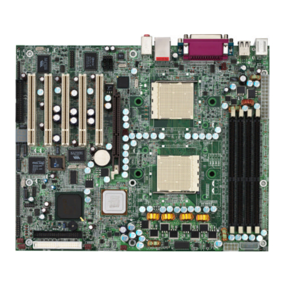
Page 8: Board Image
This picture is representative of the latest board revision available at the time of publishing. The board you receive may or may not look exactly like the above picture. The following page includes details on the vital components of this motherboard. http://www.TYAN.com... -
Page 9: Block Diagram
Header AK2001 VIA 6307 Debug system VIA 6212 Floppy Disk Drive USB 2.0 x4 Winbond PS/2 Keyboard & W83627F/HF Mouse USB Ports: 2 to backplane LPC Super I/O 2 to header Serial Port x 2 Parallel Port x 1 http://www.TYAN.com... -
Page 10: Board Parts, Jumpers And Connectors
CPU1 USB2 AMD-8111 AMD-8151 USB3 CMOS SEC-IDE FAN2 FAN1 FAN3 PRI-IDE FAN4 This diagram is representative of the latest board revision available at the time of publishing. The board you receive may not look exactly like the above diagram. http://www.TYAN.com... - Page 11 With speed control, MAX 2.0A Chassis Fan Connector Without speed control, MAX 3.0A FAN1 Chassis Fan Connector With speed control, MAX 2.0A FAN2 Chassis Fan Connector Without speed control, MAX 3.0A FAN3 Chassis Fan Connector With speed control, MAX 2.0A FAN4 http://www.TYAN.com...
-
Page 12: Chassis Intrusion Connector (J7)
PCI3 PCI2 PCI1 VIA 6212 BIOS Reset SW - PWR+ AGP1 Reset SW+ CPU1 USB2 A M D AMD-8111 SLEEP SW AMD-8151 USB3 C M O S SEC-IDE FAN2 FAN3 FAN1 IRRX PRI-IDE FAN4 IRTX Chassis Speaker Intru + http://www.TYAN.com... -
Page 13: Clear Cmos Jumper (J9)
USB (Bottom) KB(Bottom) P2_FAN LAN (Top)Optional Mouse(Top) 1394 J 3 5 AUX1 CPU2 P1_FAN S2875 PCI5 PCI4 PCI3 PCI2 PCI1 VIA 6212 BIOS AGP1 CPU1 A M D USB2 AMD-8111 AMD-8151 USB3 CMOS SEC-IDE FAN2 FAN3 FAN1 PRI-IDE FAN4 http://www.TYAN.com... -
Page 14: Usb2.0 Connector Header (J15)
USB (Bottom) KB(Bottom) P2_FAN LAN (Top)Optional Mouse(Top) 1394 AUX1 CPU2 Signal Description Pin# P1_FAN S2875 PCI5 PCI4 PCI3 PCI2 PCI1 VIA 6212 BIOS AGP1 XTPBM CPU1 USB2 AMD-8111 AMD-8151 USB3 XTPBP CMOS SEC-IDE FAN2 FAN3 FAN1 XTPAM PRI-IDE FAN4 XTPAP http://www.TYAN.com... -
Page 15: Onboard Gigabit Ethernet Lan Jumper (J26)
XYPAP XTPAM CPU2 XTPBP XTPBM P1_FAN S2875 PCI5 PCI4 PCI3 PCI2 PCI1 VIA 6212 BIOS AGP1 CPU1 USB2 AMD-8111 AMD-8151 USB3 C M O S SEC-IDE FAN2 FAN1 FAN3 PRI-IDE FAN4 Signal Signal Description Description XTPBM XTPBP XTPAM XYPAP http://www.TYAN.com... -
Page 16: Game Port Header (J34)
Signal Description Pin# J 2 4 P1_FAN S2875 J 2 2 PCI5 PCI4 PCI3 PCI2 PCI1 VIA 6212 Right Line_In BIOS AGP1 CPU1 A M D USB2 AMD-8111 AMD-8151 USB3 CMOS SEC-IDE FAN2 FAN3 FAN1 PRI-IDE FAN4 Left Line_In http://www.TYAN.com... -
Page 17: Cd Audio_In Connector (J36)
PCI2 PCI1 Max 2.0A fans supported VIA 6212 BIOS AGP1 with PWM fan control and fan speed CPU1 reading A M D USB2 A M D AMD-8111 AMD-8151 USB3 C M O S SEC-IDE FAN2 FAN3 FAN1 PRI-IDE FAN4 http://www.TYAN.com... -
Page 18: Cpu_2 Fan Connector (P2_Fan)
PCI5 PCI4 PCI3 PCI2 PCI1 VIA 6212 Max 2.0A fans supported BIOS AGP1 with PWM fan control and fan speed CPU1 reading A M D USB2 A M D AMD-8111 AMD-8151 USB3 CMOS SEC-IDE FAN2 FAN3 FAN1 PRI-IDE FAN4 http://www.TYAN.com... -
Page 19: Fan3 Chassis Fan Connector (J6)
FAN3 PRI-IDE FAN4 2.21 – OEM Reserved Connectors and Jumpers These connectors and jumpers which are not listed are reserved for OEM use only. 2.22 – POST (Power-On-Self-Test) Code LED Refer to Appendix II for BIOS POST Code list http://www.TYAN.com... -
Page 20: Installing The Processor(S)
When using a single processor only CPU1 memory banks are addressable. TYAN is not liable for damage as a result of operating an unsupported configuration. The diagram is provided as a visual guide to help you install socket processors and may not be an exact representation of the processors you have. -
Page 21: Heatsink Retention Frame Installation
The following diagram will illustrate how to install the most common CPU back plates: Mounting screw s Heatsink retention frame CPU socket Motherboard PCB Adhesive insulator material Backplate assembly NOTE: Please see next section for specific instructions on how to install mounting bracket. http://www.TYAN.com... -
Page 22: Thermal Interface Material
CPU lid (applying too much will actually reduce the cooling). Al w ays check with the manufacturer of the heatsink & processor to NOTE ensure the Thermal Interface material is compatible with the processor & meets the manufacturer’s warranty requirements http://www.TYAN.com... -
Page 23: Heatsink Installation Procedures
2. After tightening screws secure metal clip to plastic retention bracket center tab. Repeat for on other side of heatsink. 3. After securing metal clip to plastic retention bracket center tab, push down on plastic clip to lock plastic clip to side tab. http://www.TYAN.com... -
Page 24: Finishing Installing Heatsink
(which should already be attached to the heatsink) to the motherboard. The following diagram illustrates how to connect fans onto the motherboard. Once you have finished installing all the fans you can connect your drives (hard drives, CD-ROM drives, etc.) to your motherboard. http://www.TYAN.com... -
Page 25: Tips On Installing Motherboard In Chassis
Some chassis’ include plastic studs instead of metal. Although the plastic studs are usable, TYAN recommends using metal studs with screws that will fasten the motherboard more securely in place. Below is a chart detailing what the most common motherboard studs look like and how they should be installed. -
Page 26: Installing The Memory
The Tiger K8W supports up to 8GB.* * Not validated at the time of print; subject to change. This chart outlines the rules for populating memory (Note: X indicates a populated DIMM Slot) DIMM Slot 128Bit support 64-Bit Support DIMM1 DIMM2 DIMM3 DIMM4 http://www.TYAN.com... - Page 27 To remove the memory module, simply push the latches outwards until the memory module pops up. Then remove the module. YOU MUST ALWAYS unplug the power connector from the NOTE motherboard before performing system hardware changes. Otherwise you may damage the board and/or expansion device. http://www.TYAN.com...
-
Page 28: Attaching Drive Cables
2.30 – Attaching Drive Cables Attaching the IDE drive cable is simple. These cables are “keyed” to only allow them to be connected in the correct manner. TYAN motherboards have two on-board IDE channels, each supporting two drives. The black connector designates the Primary channel, while the white connector designates the Secondary channel. - Page 29 Connections for these drives are also very simple. There is no need to set Master/Slave jumpers on SATA drives. Tyan has supplied two SATA cables and one SATA power adapter. If you are in need of other cables or power adapters please contact your place of purchase.
-
Page 30: Installing Add-In Cards
YOU MUST ALWAYS unplug the power connector from the motherboard before performing system hardware changes. Otherwise NOTE you may damage the board and/or expansion device. http://www.TYAN.com... -
Page 31: Pci Riser Cards Supported On S2875 K8W
Line-In/Rear Speakers PS/2 Keyboard Line-Out/Front Speakers USB 1.1 Serial Port Serial Port USB 2.0 Ports Ports LAN Link/Activity LED Scheme Left Right Speed Link LED (left side) Activity LED (right side) 10Mbps Blink 100Mbps Orange Blink 1000Mbps Green Blink http://www.TYAN.com... -
Page 32: Installing The Power Supply
2.34 – Installing the Power Supply There are three power connectors on your Tiger K8W S2875. By default, the Tiger K8W S2875 requires that you have an EPS12V power supply that has a 24-pin and an 8-pin power connector. However, the Tiger K8W S2875 is also ATX12V compatible. All 3 power connectors need to be used if you plan on using the ATX12V power. -
Page 33: Chapter 3: Bios
Use the left/right (ß à) arrow keys to make a selection To display a sub-menu (A pointer “4” marks all sub menus) Use the arrow keys to move the cursor to the sub menu you want. Then press <Enter>. http://www.TYAN.com... -
Page 34: Bios Menu Bar
<F6> or <+> or <Space> Select the next value/setting of the field <F8> Load Fail Safe default configuration values of the menu <F9> Load the Optimal default configuration values of the menu <F10> Save and exit <Enter> Execute command or select submenu http://www.TYAN.com... -
Page 35: Bios Main Menu
System Time [12:59:59] General Help System Date [07/17/2003] F10 Save and Exit ESC Exit Feature Option Description Main System Time HH : MM : SS Set the system time System Date MM : DD : YYYY Set the system date http://www.TYAN.com... -
Page 36: Bios Advanced Menu
Configure HT links Allows control of integrated Device & PCI Slots Menu Item devices & cards plugged into Configuration PCI slots Remote Access Configuration Menu Item Configures Console Redirect Configures USB controller & USB Configuration Menu Item legacy device support http://www.TYAN.com... - Page 37 This option protects the first Disabled Hard Disk Write Protect sector of the IDE HDD from Enabled being written. Configure the time (in Seconds) IDE Detect Time Out (Sec) 35 ~ 0 before the BIOS times out on detecting an IDE Device. http://www.TYAN.com...
- Page 38 2.88 MB 3 ” Disabled This setting selects the type of 360 KB 5 ” the floppy disk drive installed in system. 1.2 MB 5 ” Floppy B 720 KB 3 ” 1.44 MB 3 ” 2.88 MB 3 ” http://www.TYAN.com...
- Page 39 Bi-Directional= send & receive data Normal Parallel Port Mode Normal= can send data EPP= Enhanced Parallel Port ECP=Extended Capability port IRQ 7 Parallel Port Interrupt Assigns IRQ to parallel port. IRQ 5 Parallel Port DMA Channel Assigns DMA channel for port. http://www.TYAN.com...
- Page 40 Displays speed of fans V1.8 RUN connected to appropriate Fan +3.3Vin headers. +5Vin -12Vin Display CPU1 and CPU2 CPU1-CPU2 Vhtlink HTLink Voltage. Enabled when chassis open Disabled Chassis Intrudsion Detect event is detected, BIOS will Enabled record the event. http://www.TYAN.com...
- Page 41 ? ? Select Screen ? ? Select Item Change Option General Help F10 Save and Exit ESC Exit Feature Option Description ACPI Configuration Yes allows the system to utilize ACPI Aware O/S ACPI (Advanced Configuration and Power Interface) specification. http://www.TYAN.com...
- Page 42 BIOS to add a pointer to an Enabled OEMB table in the Root System BIOS à AML ACPI table Description Table (RSDT) table. Note: OEMB table is used to pass Disabled POST data to the AML code during ACPI O/S operations. Enabled Headless mode Disabled http://www.TYAN.com...
- Page 43 View all unread events on the View Event Log Event Log. Mark All Events as Read Marks all events as read. Clear Event Log Erase all of events. Displays the storage capacity & Event Log Statistics usage of the Event Log. http://www.TYAN.com...
- Page 44 16 Bit Auto Specify CPU1 to AGP Hyper 200MHz Transport Link Clock frequency. CPU1: AGP HT Link Speed 400MHz 600MHz 800MHz CPU1: AGP HT Link Width Auto Specify CPU1 to AGP Hyper 2 Bit Transport Link Data width. 4 Bit http://www.TYAN.com...
- Page 45 Allows user to enable or disable Enabled Gigabit LAN Option Rom onboard Gigabit LAN controller Disabled option ROM (BIOS). Allows user to enable or disable Enabled 100/10Mbit LAN Option onboard 100/10Mbit LAN controller Disabled option ROM (BIOS). AC97 Audio Enabled http://www.TYAN.com...
- Page 46 ? ? Select Screen ? ? Select Item Change Field General Help F10 Save and Exit ESC Exit Feature Option Description Configure Remote Access type and parameters Disabled Enables remote access to Remote Access Serial system through serial port. http://www.TYAN.com...
- Page 47 Disabled USB Mouse Legacy Support contains a USB controller and Enabled you hav e a USB mouse. Select “Enabled” if your system Disabled USB Storage Device contains a USB controller and Support you have a USB Storage Enabled Device. http://www.TYAN.com...
-
Page 48: Bios Pci/Pnp Menu
[Available] IRQ15 [Available] ? ? Select Screen DMA Channel_0 [Available] DMA Channel_1 [Available] ? ? Select Item DMA Channel_3 [Available] DMA Channel_5 [Available] Change Option DMA Channel_6 [Available] General Help F10 Save and Exit DMA Channel_7 [Available] ESC Exit http://www.TYAN.com... - Page 49 Allows user to reserve a specific Available IRQ for a legacy device (Note: IRQ3 ~ IRQ15 most hardware devices & OS used Reserved do not support manual assigned). Available Allows user to reserve a specific DMA0 ~ 7 Reserved DMA for a legacy device. http://www.TYAN.com...
-
Page 50: Bios Boot Menu
? ? Select Screen Keyboard Error Report [Disabled] Boot To OS/2 [No] ? ? Select Item Wait for ‘F1’ If Error [Enabled] Change Option Hit ‘DEL’ Message Display [Enabled] General Help Interrupt 19 Capture [Disabled] F10 Save and Exit ESC Exit http://www.TYAN.com... - Page 51 Continue” error message when error is Disabled detected. Enabled Allows user to disable the “Press DEL Hit ‘DEL’ Message Display to enter setup” message during POST. Disabled Disabled Allows devices (such as network card) Interrupt 19 Capture to capture INT19 for booting. Enabled http://www.TYAN.com...
- Page 52 ? ? Select Item Change Option General Help F10 Save and Exit ESC Exit Feature Option Description Boot Device Priority Settings for boot priority. 1st FLOPPY DRIVE 1st Boot Device These can be customized Disabled depending on your preference. http://www.TYAN.com...
- Page 53 ? ? Select Item Change Option General Help F10 Save and Exit ESC Exit Feature Option Description Removable Drives Specifies the boot sequence 1st FLOPPY DRIVE for removable drive booting. 1st Device This option will show all Disabled removable devices. http://www.TYAN.com...
-
Page 54: Bios Security Menu
Supervisor Password. Select this option to change User Change User Password Password. Select this option to clear User Clear User Password Password. Disabled Protects the first sector of the Boot Sector Virus Protection Enabled Hard Drive from being written. http://www.TYAN.com... -
Page 55: Bios Chipset Setting Menu
? ? Select Screen ? ? Select Item Change Option Enter Go to Sub Screen General Help F10 Save and Exit ESC Exit Feature Option Description Chipset Settings Clock Gen. Spread Disabled Enabled/Disabled clock generator Spectrum spread spectrum feature Enabled http://www.TYAN.com... - Page 56 Bank Interleaving [Auto] Node Interleaving [Disabled] Use [+] or [-] to Burst Length [8 Beats ] configure system time. ? ? Select Screen ? ? Select Item Change Option General Help F10 Save and Exit ESC Exit http://www.TYAN.com...
- Page 57 Enabled Enables support on all nodes for Master ECC ECC error checking and correction. Disabled Disabled Enables support on all banks for DRAM ECC ECC error checking and correction. Enabled DRAM BG Scrub Disabled 40ns 80ns 160ns 320ns 640ns http://www.TYAN.com...
- Page 58 Disabled 40ns 80ns 160ns 320ns 640ns 1.28us 2.56us L2 Cache BG Scrub 5.12us 10.2us 20.5us 41.0us 81.9us 163.8us 327.7us 655.4us Data Cache BG Scrub Disabled 40ns 80ns 160ns 320ns 640ns 1.28us 2.56us 5.12us 10.2us 20.5us 41.0us 81.9us 163.8us 327.7us http://www.TYAN.com...
- Page 59 CalComp +Data value. Recommended setting is CalComp -Data Auto. Auto Auto uses hardware compensation Data values. Other values add to or HT Link 0 RZ-Comp Mode subtract from hardware generated CalComp +Data value. Recommended setting is CalComp -Data Auto. http://www.TYAN.com...
- Page 60 CalComp +Data value. Recommended setting is Auto CalComp -Data Auto Auto uses hardware compensation N Strobe Drive values. Other values add to or Data Strength subtract from hardware generated CalComp +Data value. Recommended setting is Auto. CalComp -Data http://www.TYAN.com...
-
Page 61: Bios Power Menu
APM (Advanced Power Management/APM Power Management) features. Enabled allows the chipset power Enabled management and APM features When set to Enabled, any event Disabled occurring to the COM Ring will Resume On Ring awaken a system which has powered down. http://www.TYAN.com... -
Page 62: Bios Exit Menu
General Help F10 Save and Exit ESC Exit Save Changes and Exit Use this option to exit setup utility and re-boot. All new selections you have made are stored into CMOS. System will use the new settings to boot up. http://www.TYAN.com... -
Page 63: Chapter 4: Diagnostics
(2) Graphics initialization failed Before contacting your vendor or Tyan Technical Support, be sure that you note as much as you can about the beep code length and order that you experience. Also, be ready with information regarding add-in cards, drives and O/S to speed the support process and come to a quicker solution. -
Page 64: Appendix I: Glossary
NOTE exceptions. Tyan does not have a policy for replacing BIOS chips directly with end users. In no event will Tyan be held responsible for damages done by the end user. Appendix I: Glossary ACPI (Advanced Configuration and Power Interface): a power management specification that allows the operating system to control the amount of power distributed to the computer’s devices. - Page 65 (like soundcards or keyboards) to access the main memory without involving the CPU. This frees up CPU resources for other tasks. As with IRQs, it is vital that you do not double up devices on a single line. Plug-n-Play devices will take care of this for you. http://www.TYAN.com...
- Page 66 EEPROM (Electrically Erasable Programmable ROM): also called Flash BIOS, it is a ROM chip which can, unlike normal ROM, be updated. This allows you to keep up with changes in the BIOS programs without having to buy a new chip. TYAN’s BIOS updates can be found at http://www.tyan.com ESCD (Extended System Configuration Data): a format for storing information about Plug-n- Play devices in the system BIOS.
- Page 67 RAM (Random Access Memory): technically refers to a type of memory where any byte can be accessed without touching the adjacent data and is often referred to the system’s main memory. This memory is available to any program running on the computer. http://www.TYAN.com...
- Page 68 CPUs w ithout damaging the sensitive CPU pins. The CPU is lightly placed in an open ZIF socket, and a lever is pulled down. This shifts the processor over and down, guiding it into the board and locking it into place. http://www.TYAN.com...
-
Page 69: Appendix Ii: Bios Post Code
Initialize PCI Bus Mastering Shadow video BIOS ROM devices Initialize keyboard controller Display BIOS copyright notice 1-2-2-3. BIOS ROM checksum Display CPU type and speed Initialize cache before memory Initialize EISA board autosize 8254 timer initialization Test keyboard http://www.TYAN.com... - Page 70 Try to boot with INT 19 Interrupts (NMIs) Initialize Extended BIOS Data Initialize POST Error Manager Area (PEM) Test and initialize PS/2 mouse Initialize error logging Initialize floppy controller Initialize error display function Determine number of ATA Initialize system error handler http://www.TYAN.com...
-
Page 71: Technical Support
(which can have expensive consequences). Help Resources: 1. See the beep codes section of this manual. 2. See the TYAN website for FAQ’s, bulletins, driver updates, and other information: http://www.tyan.com 3. Contact your dealer for help BEFORE calling TYAN. - Page 72 Return Merchandise Authorization (RMA) number. The RMA number should be prominently displayed on the outside of the shipping carton and the package should be mailed prepaid. TYAN will pay to have the board shipped back to you.
- Page 73 Document #: D1558-100 http://www.TYAN.com...