Panasonic KX-TA624 Installation Manual
Advanced hybrid system
Hide thumbs
Also See for KX-TA624:
- Installation manual (437 pages) ,
- User manual (234 pages) ,
- Operating instructions manual (40 pages)

Related Manuals for Panasonic KX-TA624


Summary of Contents for Panasonic KX-TA624
-
Page 1: Installation Manual
Advanced Hybrid System Installation Manual KX-TA624 Model No. Please read this manual before connecting the Advanced Hybrid System. -
Page 2: System Components
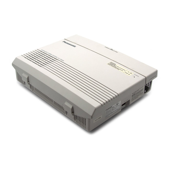
Thank you for purchasing this Panasonic Model KX-TA624, Advanced Hybrid System. System Components Model Description Service Unit KX-TA624 Advanced Hybrid System (Main Unit) KX-T7135 Proprietary telephone with backlit display KX-T7130 Proprietary telephone with display KX-T7020 Proprietary telephone Telephone KX-T7030 Proprietary telephone with display... - Page 3 Attention • Keep the unit away from heating appliances and electrical noise generating devices such as fluorescent lamps, motors and televisions. These noise sources can interfere with the performance of the Advanced Hybrid System. • This unit should be kept free of dust, moisture, high temperature (more than 40 ˚C {104 ˚F}) and vibration, and should not be exposed to direct sunlight.
- Page 4 Executive or Regional Sales offices. They are NOT equipped to make repairs. Product service Panasonic Factory Servicenters for this product are listed in the servicenter directory. Consult your authorized Panasonic dealer for detailed instructions. For your future reference...
-
Page 5: Important Safety Instructions
Important Safety Instructions When using your telephone equipment, basic safety precautions should always be followed to reduce the risk of fire, electric shock and injury to persons, including the following: 1. Read and understand all instructions. 2. Follow all warnings and instructions marked on the product. 3. -
Page 6: Save These Instructions
Important Safety Instructions 11. Never push objects of any kind into this product through cabinet slots as they may touch dangerous voltage points or short out parts that could result in a risk of fire or electric shock. Never spill liquid of any kind on the product. - Page 7 Telephone Company and F.C.C. Requirements and Responsibilities 1. Notification to the Telephone Company Customers, before connecting terminal equipment to the telephone network, shall upon request of the Telephone Company, inform the Telephone Company of the particular line(s) to which such connection is made, the F.C.C.
- Page 8 • Make ........Panasonic...
- Page 9 This Installation Manual provides technical information for the Panasonic Advanced Hybrid System, KX-TA624. It is designed to serve as an overall technical reference for the system and includes a description of the system, its hardware and software, features and services and environmental requirements.
-
Page 10: Table Of Contents
Contents Section 1 System Outline RRRRRRRRRRRRRRRRRRRRR 1-2 System Highlights RRRRRRRRRRRRRRRRR 1-3 Basic System Construction Proprietary Telephones RRRRRRRRRRRRRRRRRRR 1-3 Options RRRRRRRRRRRRRRRRRRRRRRRRRR 1-4 3 CO Line and 8 EXT Expansion Card (KX-TA62477) RRRRRRR 1-4 1.4.1 8 Extension Expansion Card (KX-TA62470) RRRRRRRRRRR 1-4 1.4.2 Caller ID Card (KX-TA62493) RRRRRRRRRRRRRRRR 1-4 1.4.3... - Page 11 Contents Section 3 Features Absent Message Capability RRRRRRRRRRRRRRRRRRRRR 3-2 Account Code Entry RRRRRRRRRRRRRRRRRRRRRRRR 3-3 Answering, Direct Outside (CO) Line RRRRRRRRRRRRRRRRR 3-4 Automatic Callback Busy (Camp-On) RRRRRRRRRRRRRRRRR 3-5 Background Music (BGM) RRRRRRRRRRRRRRRRRRRRR 3-6 Busy Lamp Field RRRRRRRRRRRRRRRRRRRRRRRRR 3-7 Busy Station Signaling (BSS) RRRRRRRRRRRRRRRRRRRR 3-7 Button, Direct Station Selection (DSS) RRRRRRRRRRRRRRRRR 3-8 Button, Flexible RRRRRRRRRRRRRRRRRRRRRRRRRR 3-9 Button, Group-CO (G-CO) RRRRRRRRRRRRRRRRRRRRR 3-11...
-
Page 12: Rrrrrrrrrrrrrrrrrrrrr
Contents Direct In Lines (DIL) RRRRRRRRRRRRRRRRRRRRRRR 3-44 RRRRRRRRRRRRRRRR 3-45 Direct Inward System Access (DISA) Display, Call Information RRRRRRRRRRRRRRRRRRRRR 3-51 RRRRRRRRRRRRRRRRRRRRRRRRR 3-52 Display, in Idle Display, Self-Extension Number RRRRRRRRRRRRRRRRRRR 3-53 Display Contrast Adjustment RRRRRRRRRRRRRRRRRRRR 3-53 Do Not Disturb (DND) RRRRRRRRRRRRRRRRRRRRRR 3-54 RRRRRRRRRRRRRRRRRR 3-54 Do Not Disturb (DND) Override Door Opener RRRRRRRRRRRRRRRRRRRRRRRRRR 3-55... -
Page 13: Rrrrrrrrrrrrrrrrrrrrrr
Contents Operator RRRRRRRRRRRRRRRRRRRRRRRRRRRR 3-94 Operator Call RRRRRRRRRRRRRRRRRRRRRRRRRR 3-94 Outgoing Message (OGM) RRRRRRRRRRRRRRRRRRRRR 3-95 Outside (CO) Line Connection Assignment RRRRRRRRRRRRRR 3-98 RRRRRRRRR 3-98 Outside (CO) Line Connection Assignment – Outgoing Outside (CO) Line Group RRRRRRRRRRRRRRRRRRRRR 3-99 PAGING FEATURES – SUMMARY RRRRRRRRRRRRRRRR 3-100 Paging –... - Page 14 Contents Section 4 System Programming General Programming Instructions RRRRRRRRRRRRRR 4-2 Using Proprietary Telephones RRRRRRRRRRRRRRRRR 4-3 4.1.1 Programming Methods RRRRRRRRRRRRRRRRRRRR 4-5 4.1.2 Entering Characters RRRRRRRRRRRRRRRRRRRRR 4-6 4.1.3 RRRRRRRRRRRRRRRRRRR 4-8 4.1.4 Programming Example System Programming RRRRRRRRRRRRRRRRRRRR 4-9 Date and Time Setting RRRRRRRRRRRRRRRRRRRR 4-9 [000] System Speed Dialing Entry RRRRRRRRRRRRRRRRR 4-11 [001]...
- Page 15 Contents No Dial Disconnection RRRRRRRRRRRRRRRRRRR 4-52 [211] Carrier Code Assignment RRRRRRRRRRRRRRRRRR 4-53 [300] Toll Restriction — System Speed Dialing Boundary Class RRRRR 4-54 [301] [302]–[305] Toll Restriction — Class 2 – 5 Denied Codes RRRRRRRR 4-55 Toll Restriction — Exception Codes RRRRRRRRRRRRRR 4-56 [306] Emergency Dial Number Set RRRRRRRRRRRRRRRRR 4-57 [309]...
-
Page 16: Connection Rrrrrrrrrrrrrrrrrrrrrrrr
Contents Extension Name Setting RRRRRRRRRRRRRRRRRR 4-104 [604] Account Code Entry Mode RRRRRRRRRRRRRRRRR 4-105 [605] Call Transfer to an Outside (CO) Line RRRRRRRRRRRRR 4-107 [606] Call Forwarding to an Outside (CO) Line RRRRRRRRRRR 4-108 [607] Executive Busy Override RRRRRRRRRRRRRRRRRR 4-109 [608] Do Not Disturb Override RRRRRRRRRRRRRRRRRR 4-110 [609] Paralleled Telephone Connection RRRRRRRRRRRRRRR 4-111... -
Page 17: System Outline
Section 1 System Outline This section provides general information on the system, including system capacity and specifications. -
Page 18: System Highlights
A PC is not required. Voice Mail Integration The system supports Voice Processing Systems with in-band DTMF signaling as well as APT Integration. The Panasonic Voice Processing System provides Automated Attendant, Voice Mail, Interview and Custom Services. Caller ID Allows the user to see the name or telephone number of a caller on the telephone display before answering a call. -
Page 19: Basic System Construction
Basic System Construction The KX-TA624 Advanced Hybrid System has a basic capacity of three outside (CO) lines and eight extensions. It is capable of supporting Panasonic analog proprietary telephones, and single line devices such as single line telephones and a fax machine. - Page 20 Options 1.4.1 3 CO Line and 8 EXT Expansion Card (KX-TA62477) Adds three outside (CO) lines (outside (CO) lines 4 through 6) and eight extensions (JACK 09 through 16). 1.4.2 8 Extension Expansion Card (KX-TA62470) Adds eight extensions (JACK 17 through 24). 1.4.3 Caller ID Card (KX-TA62493) This card supports the following.
- Page 21 1.4.5 Doorphone/Door Opener Card (KX-TA62460) This card supports four doorphones and four door openers. The doorphone is optional (KX-T30865). Doorphone 1 Doorphone 2 Doorphone 3 Doorphone 4 Door Door Door Door Opener 1 Opener 2 Opener 3 Opener 4 1.4.6 DSS Console (KX-T7040) Allows easy and quick access to stations and features.
-
Page 22: General Description
Specifications 1.5.1 General Description System Capacity Outside (CO) Lines 3 max. (6 max. with a 3 CO Line and 8 EXT Expansion Card) Extensions 8 max. (24 max. with a 3 CO Line and 8 EXT Expansion Card and 8 Extension Expansion Card) Control Method CPU: 16 bit CPU... - Page 23 1.5.2 Characteristics Station Loop Limit KX-T7020 / KX-T7030 / KX-T7050 / KX-T7055 / KX-T7130 / KX-T7135 ....40 Ω Single Line Telephone ....600 Ω including set Doorphone .
- Page 24 1.5.3 System Capacity Lines, Cards, Station Equipment Item Max. Quantity Service Units Outside (CO) Lines Extension Jacks Station Terminals 3 CO Line and 8 EXT Expansion Card 8 Extension Expansion Card Caller ID Card OGM/FAX Detection Card Doorphone/Door Opener Card Doorphones Door Openers External Pager...
- Page 25 Section 2 Installation This section contains the basic system installation and wiring instructions, as well as how to install the optional cards and units.
-
Page 26: Before Installation
7. Install at least 1.8 m {6 feet} away from radios and televisions. (Both the system and Panasonic proprietary telephones) 8. Do not obstruct area around the system (for reasons of maintenance and inspection — be especially careful to allow space for cooling above and at the sides of the system). - Page 27 4. Please use one pair telephone wire for extension connection of (telephone) equipment such as single line telephones, data terminals, answering machines, computers, voice processing systems, etc., except Panasonic proprietary telephones (e.g., KX-T7030, KX-T7130). 5. Unplug the system during wiring. After all of the wiring is completed, plug in the system.
-
Page 28: Installation Of The Main Unit
Installation of the Main Unit 2.2.1 Unpacking Unpack the box and check the items below. Main Unit AC Cord Screws (Wall Mounting) three Washers (Wall Mounting) three Pager Connector Music Source Connector 2.2.2 Location of Interfaces External Music Jack Paging Jack Extension Modular Jacks Strap (for cables) Outside (CO) Line Modular Jacks... -
Page 29: Wall Mounting
2.2.3 Wall Mounting This set is designed for wall mounting only. The wall where the main unit is to be mounted must be able to support the weight of the main unit. If screws other than the ones supplied are used, use screws with the same diameter as the ones enclosed. -
Page 30: Frame Ground Connection
2.2.4 Frame Ground Connection IMPORTANT!!! Connect the frame of the main unit to the ground. 1. Loosen the screw. 2. Insert the grounding wire. 3. Tighten the screw. 4. Connect the grounding wire to the ground. To the ground Screw In most of North America, the ground provided by the “Third wire ground”... -
Page 31: System Connection Diagram Rrrrrrrrrrrrrrrrr
Connection 2.3.1 System Connection Diagram : needs an Optional Card. 6 Outside (CO) Lines to outside (CO) lines 1 – 3 (initial) to outside (CO) lines 4 – 6 (additional) (Lightning Protectors) External Music Source Amplifier Speaker Printer Computer Extension jacks 01 – 08 (initial) 24 Extensions Extension jacks 09 –... -
Page 32: Opening The Front Cover
2.3.2 Opening the Front Cover 1. Loosen the screw. 2. Remove the top front cover. Top front cover Screw Note The screw cannot be removed from the cover. Installation... -
Page 33: Outside (Co) Line Connection Rrrrrrrrrrrrrrrr
2.3.3 Outside (CO) Line Connection Connection 1. Insert the modular plugs of the telephone line cords (2-conductor wiring) into the modular jacks on the system. 2. Connect the line cord to the terminal board or the modular jacks from the Central Office jack. View of TEL Jack (Outside (CO) Line) T: Tip R: Ring... - Page 34 2.3.3 Outside (CO) Line Connection Installing Lightning Protectors A lightning protector is a device to be installed on an outside (CO) line to prevent a dangerous surge from entering the building and damaging the equipment. A dangerous surge can occur if a telephone line comes in contact with a power line.
- Page 35 2.3.3 Outside (CO) Line Connection Installation of an Earth Rod Lightning Protectors Grounding Wire System (Underground) 1) Installation location of the earth rod ..Near the protector 2) Check obstructions ....None 3) Composition of the earth rod .
-
Page 36: Extension Connection Rrrrrrrrrrrrrrrrrrr
2.3.4 Extension Connection Extension jacks 01 – 08 are for all kinds of telephones. Telephone Wiring The maximum length of the extension line cord (twisted cable) which connects the system and the extension is as follows. Diameter of the line Max. -
Page 37: External Pager (Paging Equipment) Connection Rrrrrrrrr
2.3.5 External Pager (Paging Equipment) Connection One external pager (user-supplied) can be connected to the KX-TA624 as illustrated below. Use an EIAJ RC-6701 A plug (two-conductor, ø 3.5 mm in diameter). • Output impedance: 600 Maximum length of the cable AWG 18 –... -
Page 38: External Music Source Connection Rrrrrrrrrrrrrr
2.3.6 External Music Source Connection One music source, such as a radio (user-supplied), can be connected to the KX-TA624 as illustrated below. Insert the plug to the earphone/headphone jack on the external music source. Use an EIAJ RC-6701 A plug (two-conductor, ø... -
Page 39: Paralleled Telephone Connection
Any single line telephone can be connected in parallel with a proprietary telephone as follows. Using a Modular T-Adaptor Modular T-Adaptor (Panasonic KX-J66 or USOC RJA2X) 2-conductor wiring cord Connect pins “T” and “R”. 4-conductor wiring cord For a proprietary telephone: Connect pins “T”, “R”, “H”... -
Page 40: Polarity Sensitive Telephone Connection Rrrrrrrrrrrr
2.3.8 Polarity Sensitive Telephone Connection If the telephone is polarity sensitive, follow the procedure below: 1. Complete all the required extension wiring. 2. Confirm that dialing can be done from all the extensions using a touchtone telephone. If dialing fails, the polarity between the extension and the system must be reversed. -
Page 41: Printer And Pc Connection
2.3.9 Printer and PC Connection A user-supplied printer or personal computer (PC) can be connected to the system. These are used to print out or refer to the SMDR call records and system programming data. Connect the printer cable or the PC cable to the Serial Interface (RS-232C) connector. -
Page 42: Printer And Pc Connection Rrrrrrrrrrrrrrrrr
2.3.9 Printer and PC Connection Connection Chart for a Printer / Personal Computer with the KX-TA624 If a printer or a PC with a 9-pin cable is connected, follow the chart below. System 9-pin Cable Printer/PC Circuit Circuit Signal Signal... - Page 43 2.3.9 Printer and PC Connection Serial Interface (RS-232C) Signals Frame Ground: FG Connects the unit frame and the earth ground conductor of the AC power cord. Transmitted Data: SD (TXD) ....(output) Conveys signals from the unit to the printer.
-
Page 44: Installation Of Optional Cards Rrrrrrrrrrrrrrrr
Installation of Optional Cards 2.4.1 Location of Optional Cards The location of the optional cards is shown below. Precaution To protect the printed circuit boards (P-boards) from static electricity, do not touch parts on the P-boards in the main unit and on the optional cards. -
Page 45: Caller Id And Ogm/Fax Detection Card Installation Rrrrrrr
2.4.2 Caller ID and OGM/FAX Detection Card Installation A Caller ID Card (KX-TA62493) and OGM/FAX Detection Card (KX-TA62491) can be installed to the system. The Caller ID Card supports the following. Caller ID: Receives the Caller ID Service from the Central Office. A display proprietary telephone with Caller ID service can display the information. - Page 46 2.4.2 Caller ID and OGM/FAX Detection Card Installation 3. Attach the optional cards. Caller ID Card (KX-TA62493) OGM/FAX Detection Card Install the Caller ID Card for (KX-TA62491) the KX-TA62477 here. Note Please do not damage this part. 4. Insert the flat cables to each card connector. Flat cables 5.
-
Page 47: Doorphone And Door Opener Connection
2.4.3 Doorphone and Door Opener Connection Four doorphones (KX-T30865) and four door openers (user- supplied) can be installed. Maximum cable length The maximum length of the doorphone and door opener line cord which connects the system is as follows. Diameter of the line Max. -
Page 48: Doorphone And Door Opener Connection Rrrrrrrrrrr
2.4.3 Doorphone and Door Opener Connection Doorphone/Door Opener Installation Attach the Doorphone/Door Opener Card to the main unit, connect the cord to the doorphone/door opener card connector and secure the screw. Doorphone Connectors Screw Door Opener Terminal Doorphone/Door Opener Card (KX-TA62460) Doorphone/Door Opener Card Card Connector... - Page 49 2.4.3 Doorphone and Door Opener Connection Wiring of the Doorphone 1. Connect the Doorphone/Door Opener Card to the terminal boxes using 4-conductor modular connectors. 2. Connect the wires of doorphones 1 and 3 to the red and green screws on the terminal box. 3.
- Page 50 2.4.3 Doorphone and Door Opener Connection Connecting Door Openers While pressing the button below a hole with a driver, insert the wire from the door opener into the hole. Door opener 1 Door opener 4 Door opener 2 Door opener 3 Note •...
- Page 51 2.4.3 Doorphone and Door Opener Connection Programming References Section 4, System Programming [700]–[702] Doorphone Ringing Assignment — Day/Night/Lunch [703]–[705] Door Opener Assignment — Day/Night/Lunch Feature References Section 3, Features Door Opener Doorphone Call Installation 2-27...
-
Page 52: Installing A 3 Co Line And 8 Ext Expansion Card (Kx-Ta62477) And 8 Extension Expansion Card (Kx-Ta62470) Rrrrrrr
2.4.4 Installing a 3 CO Line and 8 EXT Expansion Card (KX- TA62477) and 8 Extension Expansion Card (KX-TA62470) 3 CO Line and 8 EXT Expansion Card Installation (KX-TA62477) To add three outside (CO) lines (outside (CO) lines 4 through 6) and eight extensions (JACK 09 through 16), use an optional 3 CO Line and 8 EXT Expansion card (KX-TA62477). - Page 53 2.4.4 Installing a 3 CO Line and 8 EXT Expansion Card (KX- TA62477) and 8 Extension Expansion Card (KX-TA62470) 4. After cutting the areas, be sure to cut off any excess plastic in order to make the surface smooth. Installation 2-29...
- Page 54 2.4.4 Installing a 3 CO Line and 8 EXT Expansion Card (KX- TA62477) and 8 Extension Expansion Card (KX-TA62470) 5. First, insert the plastic spacer into the hole near the Caller ID card connector on the KX-TA62477. Attach the extension connectors to the system, install the KX-TA62477 and secure the two extension bolts.
- Page 55 2.4.4 Installing a 3 CO Line and 8 EXT Expansion Card (KX- TA62477) and 8 Extension Expansion Card (KX-TA62470) Installing the KX-TA62470 1. Power off the system, and unplug the AC cord. 2. Loosen the screws and open the top and bottom front covers. 3.
- Page 56 2.4.4 Installing a 3 CO Line and 8 EXT Expansion Card (KX- TA62477) and 8 Extension Expansion Card (KX-TA62470) When you install the KX-TA62470 to the KX-TA62477, install the KX-TA62477 first and then the KX-TA62470. Screws 8 Extension Expansion Card (KX-TA62470) Extension Bolts Extension Connectors...
-
Page 57: Securing The Cords Rrrrrrrrrrrrrrrrrrrrr
2.4.5 Securing the cords 1. Wrap the strap around all of the cords. 2. Close the covers and secure the screws. Note • To remove the strap, loosen the rivet with a driver. Rivet Installation 2-33... -
Page 58: Auxiliary Connection For Power Failure Transfer Rrrrrrrr
Auxiliary Connection for Power Failure Transfer Power failure transfer connects a specific single line telephone to selected outside (CO) lines in the event of system power failure, as follows. Outside (CO) Line 1 – Extension (T, R) Jack 01 Outside (CO) Line 4 – Extension (T, R) Jack 09 Connection of outside (CO) lines 1 and 4, and the respective extensions require no auxiliary connection. -
Page 59: Closing The Front Cover
Closing the Front Cover 1. Replace the covers and tighten the screws. 2. Tie together all of the connected cords and attach them to the wall so that the cords cannot be pulled out of the system. Installation 2-35... -
Page 60: Starting The System For The First Time Rrrrrrrrrrrr
Starting the System for the First Time 1. Plug the AC power cord into the system and an AC outlet. 2. Turn the Power Switch on. (The power indicator will light.) 3. Perform the following operation with a proprietary telephone connected to JACK 01. -
Page 61: System Restart Rrrrrrrrrrrrrrrrrrrrrr
System Restart After starting the system, if the system does not operate properly, restart the system. Before restarting the system, try the system feature again to confirm whether there definitely is a problem or not. System Restart causes the following. 1. -
Page 62: System Data Clear Rrrrrrrrrrrrrrrrrrrr
System Data Clear When the system does not operate properly after restarting, you can clear the programming data stored in the system. The system will restart with the default settings. First, try system program [999]. If the system still does not operate properly, please follow the procedure below. - Page 63 Section 3 Features This section describes every basic, optional, and programmable feature in alphabetical order. It also provides information about the conditions, connection references, programming required, related features, and operation for every feature.
-
Page 64: User Manual
Features bsent Message Capability Description Allows an extension user to set a message which will be displayed at the calling extension to show the reason for the called extension’s absence. Six messages can be programmed as desired, which are available for every extension user. Setting or canceling a message can be done by individual extension users but only callers with a display telephone can view the message. - Page 65 Features ccount Code Entry Description An Account Code is used to identify incoming and outgoing outside calls for accounting and billing purposes. The account code is appended to the Station Message Detail Recording (SMDR) call record. For incoming outside calls, account codes are optional. For outgoing outside calls, there are four modes available to enter an account code: Verify-All mode, Verify-Toll mode, Forced mode, and Option mode.
- Page 66 Features nswering, Direct Outside (CO) Line Description Allows a proprietary telephone user to answer an incoming call by simply pressing the appropriate CO button without lifting the handset or pressing the SP-PHONE/MONITOR button. Condition • This feature allows the user to specify which line will be answered when multiple incoming lines are ringing.
- Page 67 Features utomatic Callback Busy (Camp-On) Description Allows the caller to be notified when the called party or selected outside (CO) line becomes free. Automatic Callback – Extension If the caller answers the callback ringing (Camp-On Recall), the called extension will automatically start ringing. Automatic Callback –...
- Page 68 Features ackground Music (BGM) Description Allows a proprietary telephone user to listen to background music from the speaker monitor on their telephone. Conditions • A user-supplied external music source, such as a radio, must be connected. One external music source can be connected to the system. •...
- Page 69 Features usy Lamp Field Description The LED (Light Emitting Diode) indicators of the DSS (Direct Station Selection) buttons, corresponding to selected extensions, show whether the extensions are idle or busy. Conditions • This function is available for flexible CO buttons assigned as DSS buttons on proprietary telephones and DSS buttons on DSS Consoles.
- Page 70 Features utton, Direct Station Selection (DSS) Description A DSS button allows a proprietary telephone user one-touch access to other extension users. Conditions • A flexible CO button and MESSAGE button on a proprietary telephone can be assigned as a DSS button using station programming. •...
- Page 71 Voice Mail Transfer† Direct Station Selection (DSS) One-Touch Dialing “ ” indicates that the feature is available. † Available when the KX-TA624 is connected to a Proprietary Telephone capable Panasonic Voice Processing System (one that supports APT Integration; KX-TVS50/KX-TVS80). Features...
- Page 72 Features Condition • Incoming and outgoing calls on a line are shown in the following priority. Single-CO > Group-CO Programming References Station Programming ....User Manual Flexible Button Assignment DSS Console Features (KX-T7040) .
- Page 73 Features utton, Group-CO (G-CO) Description To support efficient utilization of outside (CO) lines, a group of outside (CO) lines (outside (CO) line group) can be assigned to a CO button. The function is referred to as Group-CO (G-CO). Any incoming call from any outside (CO) line in the outside (CO) line group arrives at the G-CO button.
- Page 74 Features utton, Other-CO (O-CO) Description Outside (CO) lines, which are not assigned to a S-CO or G-CO button, can be assigned to a flexible CO button on a proprietary telephone (PT). The assigned button serves as the Other-CO (O-CO) button. An incoming call on an outside (CO) line arrives at the O-CO.
- Page 75 Features utton, Single-CO (S-CO) Description A Single-CO (S-CO) button is an outside (CO) line access button. This allows a proprietary telephone user to access a specific line by pressing a S-CO button. An incoming call can be directed to a S-CO button.
- Page 76 Features uttons on Proprietary Telephones Description Proprietary telephones are provided with the feature/line access buttons listed below. KX-T Proprietary Telephones Buttons 7020 7030 7050 7055 7130 7135 AUTO ANSWER/MUTE AUTO DIAL/STORE CO * (12) (12) (12) (12) (12) CONF FLASH FWD/DND HOLD INTERCOM...
- Page 77 Features The functions of the listed buttons are described below. AUTO ANSWER/MUTE: Used for answering an extension automatically, or turns the microphone off during a conversation. AUTO DIAL/STORE: Used for System Speed Dialing and storing program changes. CO (Central Office line): Can make or receive an outside call or can be re-assigned to a different CO or various feature buttons.
- Page 78 Features ALL FORWARDING FEATURES – SUMMARY Description Call Forwarding features enable an extension user to have their calls forwarded to a specified destination. The user may determine the conditions of how their calls will be forwarded. The following Call Forwarding features are available: Call Forwarding –...
- Page 79 Features all Forwarding – Busy/No Answer Description A user’s calls are forwarded to another extension if their extension is busy or they do not answer the call within a pre-determined time. Conditions • The types of calls which are forwarded by this feature are: Outside calls –...
-
Page 80: Feature Reference
Features all Forwarding – Follow Me Description If a user forgets to set Call Forwarding – All Calls before they leave their desk, this allows them to set the same feature from the destination extension. Condition • Same as the conditions for Call Forwarding – All Calls. •... - Page 81 Features all Forwarding – to an Outside (CO) Line Description Calls directed to an extension will be sent to an external destination. The outside telephone number must be pre-programmed. Conditions • The types of calls which are forwarded by this feature are: Outside calls –...
- Page 82 Features all Hold – Intercom Description This is used to place an intercom call on hold. The held call can be retrieved by the user who held it or by any other extension. Conditions • Only one intercom call can be placed on hold (up to ten calls in the system –...
- Page 83 Features all Hold – Outside (CO) Line Description Allows an extension user to put an outside call on hold. The held call can be retrieved by the user who held it or by any other extension. Conditions • With a single line telephone, the user can hold only one call, either an extension or outside call.
- Page 84 Features all Hold, Exclusive – Intercom Description Allows a proprietary telephone user to prevent other extension users from retrieving a held intercom call. Only the user who held the call can retrieve it. Conditions • Only one intercom call can be placed on Call Hold or Exclusive Call Hold at a time.
- Page 85 Features all Hold Retrieve – Intercom Description Allows an extension user to retrieve a call that has been placed on hold by another extension. Condition A confirmation tone is sent to the user when the hold is retrieved by entering the feature number. Programming References No programming required.
- Page 86 Features all Log, Incoming Description If display proprietary telephone (KX-T7030, KX-T7130 or KX- T7135) users cannot answer a call, the incoming outside call information from the Caller ID service is automatically logged in the system and the Caller ID Indication button indicator lights. Moreover, the user can call back the caller by checking the call log.
- Page 87 Features • A telephone user can lock their display so that the incoming call information stored in their personal area is not shown on the display. The operator or manager can cancel the lock. The call information stored in the common area can be locked and unlocked only by the operator and manager.
- Page 88 Features all Park Description Allows an extension user to place a held call into a system parking area. This releases the user from the parked call to perform other operations. The parked call can be retrieved by any extension user. Conditions •...
- Page 89 Features all Pickup, Group Description Allows an extension user to answer a call that is ringing at another telephone, if the call is ringing within the user’s extension group. Conditions • The user can pick up an incoming outside, intercom, or doorphone call. •...
- Page 90 Features all Retrieving from a TAM (Telephone Answering Machine) Description Allows an extension user to answer an incoming call received by TAM. Conditions None Programming Reference Section 4, System Programming [611] TAM (Telephone Answering Machine) Extension Feature References None Operation Reference Telephone Features —...
- Page 91 Features ALL TRANSFER FEATURES – SUMMARY Description Call Transfer features allow a user to transfer a call to another party. This operation can be screened or unscreened. Screened call transfer is used when the user wants to announce the call to the other party before completing the transfer.
- Page 92 Features all Transfer, Screened – to an Outside (CO) Line Description Allows a proprietary telephone user to voice-announce to an external party and transfer the call. Conditions • System programming determines which extensions are able to perform this feature. • A single line telephone user cannot transfer a received call to an external party.
- Page 93 Features all Transfer, Unscreened – to Extension Description Allows a user to transfer an intercom or outside call directly to an extension party. After dialing the destination extension, the user waits for the ringback tone and replaces the handset. Conditions •...
- Page 94 Features all Waiting Description During a conversation, a call waiting tone notifies the user that another incoming call is waiting. They can answer the second call by disconnecting or placing the current call on hold. The call waiting tone can be activated or deactivated by dialing the appropriate feature number.
- Page 95 Features all Waiting from a Central Office Description During a conversation, a call waiting tone offered by the Central Office notifies the user that another incoming call is waiting. They can answer the second call by placing the current call on hold. Conditions None Programming References...
- Page 96 Features aller ID Description Provides a display proprietary telephone user with the caller’s information, such as their name and telephone number, on the outside (CO) line assigned to receive Caller ID service calls. Conditions • The outside (CO) lines where the Caller ID service is offered by a Central Office must be assigned.
- Page 97 Features aller ID Call Waiting Description During a conversation, a call waiting tone offered by the Central Office informs the user that there is a call waiting. If the Caller ID service provides them with a caller’s information, such as the name and telephone number, the new caller’s information will be displayed (flashing) on their extension (KX-T7030, KX-T7130 and KX-T7135 only) during the assigned time.
- Page 98 Features alling Party Control (CPC) Signal Detection Description The Calling Party Control (CPC) Signal is an on-hook indication (disconnect signal) sent from the outside (CO) line when the telephone is hung up at the other end. To maintain efficient utilization of outside (CO) lines, the system monitors their state and when a CPC Signal is detected from a line, the system disconnects the line and alerts the extension with a reorder tone.
- Page 99 Features onference Description The system supports three-party conference calls, including external or internal parties. During a two-party conversation, the extension user can add a third party to their conversation, thereby establishing a conference. Conditions • Possible conference combinations are:1-intercom and 2-outside calls; 2-intercom and 1-outside calls;...
- Page 100 Features onference, Unattended Description When a proprietary telephone user is in a conference with two external parties, the user can leave the conference to allow the other two parties to continue the conversation. This is called an Unattended Conference. The user may return to the conference, if desired.
- Page 101 Features onfirmation Tones Description When various features are completed, the system confirms the success of the operation by sending a confirmation tone to the extension user through the speaker of the telephone. Confirmation tone 1: (a) Indicates that the new setting is different from the previous setting.
- Page 102 Features Confirmation tone 4: Sent when changing a three-party call (created by Executive Busy Override or Conference) to a two-party call. This tone can be disabled by system programming. Condition • Confirmation Tones 1 and 2 are provided to reconfirm assigned features. Programming References Section 4, System Programming [105] Conference Tone...
- Page 103 Features ata Line Security Description Data Line Security is a feature that can be set at individual extensions. Once set, communication between the extension and the other party is protected from signals such as Call Waiting, Hold Alarm/Hold Recall and Executive Busy Override. Data equipment or a facsimile may be connected to an extension jack so that the user can perform data communications.
- Page 104 Features ial Tones, Distinctive Description Three types of dial tone patterns are available to give information about features activated on the telephone. Dial tone 1: This is a normal dial tone. None of the features listed below are activated. Dial tone 2: Sent when any one of the features below are set. Absent Message Capability Background Music (BGM) (for proprietary telephones only) Call Forwarding...
- Page 105 Features ial Type Selection Description Allows an extension user to select the desired dialing mode for each outside (CO) line regardless of the originating extension (rotary or tone). There are three dialing modes available. DTMF (Dual Tone Multi-Frequency) Mode The dialing signal from an extension, either tone or rotary, is converted to tone dialing.
- Page 106 Features irect In Lines (DIL) Description Enables an incoming outside call to go directly to one extension. DIL places an incoming outside call to only one extension. This outside (CO) line can be used by multiple extension users to make calls, but can only be used by one extension to receive calls.
- Page 107 Features irect Inward System Access (DISA) Description Allows an outside caller to access specific system features as if the caller is an extension in the system. The caller can have direct access to features such as: • Placing an incoming call to an extension, operator or ring group.
- Page 108 Features • The DISA built-in auto attendant number may be the same as the first digit of other numbers (extension number, etc.). To avoid confusion, the system waits for the second digit for a preprogrammed amount of time (default: 2 seconds). If the timer expires, the system will assume that the first digit is a DISA built-in auto attendant number.
- Page 109 Features To enable the Intercept Routing feature [408]–[410] Flexible Ringing Assignment — Day/Night/Lunch [507] DISA Intercept Mode [508] DISA Ringing Time before Intercept [509] DISA Ringing Time after Intercept [515] Intercept Time For Internal DISA Feature References Section 3, Features Intercept Routing Outgoing Message (OGM) Operation Reference...
- Page 110 Features Flow chart of possible cases and results for DISA calls An outside line call is made. The caller reaches the DISA line. Without optional With optional OGM/FAX Detection Card OGM/FAX Detection Card (Internal DISA) @ @ @ @ @ @ @ @ e ? @ @ @ @ @ @ @ @ e ? @ @ @ @ @ @ @ @ ? e @ @ @ @ @ @ @ @ e ? @ @ @ @ @ @ @ @ ? e @ @ @ @ @ @ @ @ e ? @ @ @ @ @ @ @ @ ? e @ @ @ @ @ @ @ @ e ? @ @ @ @ @ @ @ @ ? e @ @ @ @ @ @ @ @ e ? @ @ @ @ @ @ @ @ ? e @ @ @ @ @ @ @ @ e ? @ @ @ @ @ @ @ @ ? e @ @ @ @ @ @ @ @ e ? @ @ @ @ @ @ @ @ e ? @ @ @ @ @ @ @ @ ? e @ @ @ @ @ @ @ @ e ? @ @ @ @ @ @ @ @ ? e @ @ @ @ @ @ @ @ e ? @ @ @ @ @ @ @ @ ? e @ @ @ @ @ @ @ @ e ? @ @ @ @ @ @ @ @ ? e @ @ @ @ @ @ @ @ e ? @ @ @ @ @ @ @ @ ? e @ @ @ @ @ @ @ @ e ? @ @ @ @ @ @ @ @ ? e @ @ @ @ @ @ @ @ e ? @ @ @ @ @ @ @ @ @ @ @ @ @ @ @ @ e ?
- Page 111 Features *1: The DISA Delayed Timer starts. This is the time between a call reaching the system and being received. The time is assigned in program [504] “DISA Delayed Answer Time”. *2: When a call is received and the system answers, the system sends a short beep to the caller. *3: The Intercept Timer for Internal DISA starts.
- Page 112 Features *10: The DISA Busy Mode is selected in program [506] “DISA Busy Mode”. There are three modes as follows: • Disconnect – the caller hears a busy tone and the call is disconnected. • Call Waiting – the destination extension hears the call waiting tone if they have enabled Call Waiting.
- Page 113 Number or name of the caller These are shown if the Caller ID feature is available. Display examples: 1234567890 Panasonic Call duration This is shown during an established outside call. The display remains for five seconds after the call is finished.
- Page 114 Features isplay, in Idle Description A display proprietary telephone can display: (1) date and time, (2) date and day of the week, or (3) extension number and name. One of the following displays is displayed while on-hook. The user can change the display by pressing the key.
- Page 115 Features isplay, Self-Extension Number Description Allows a display proprietary telephone user to display their own jack number and extension number in the station programming mode. Condition • Display example If the jack number is 02 and the extension number is 102: Jack02<=>EXT102 Programming Reference Station Programming .
- Page 116 Features o Not Disturb (DND) Description Allows an extension user to appear busy to incoming outside or intercom calls. This can be set or canceled by the extension user. Conditions • If a proprietary telephone (PT) is not supplied with the FWD/DND button, it can be assigned to a flexible CO button.
- Page 117 Features oor Opener Description Allows extension users to unlock the door for a visitor from their telephone. The door can be unlocked by extension users who have been programmed to enable this feature. Conditions • An optional Doorphone/Door Opener card must be installed. •...
- Page 118 Features oorphone Call Description If a visitor presses the doorphone button, pre-assigned extensions will be called. The extension who answers the call can talk to the visitor. Any extension user can call a doorphone. The doorphones are also used for the Room Monitor feature. Conditions •...
- Page 119 Features SS Console (KX-T7040) Description The Direct Station Selection (DSS) Console provides direct access to stations, a busy lamp display, as well as 16 PF (Programmable Feature) buttons. The DSS Console must be programmed to work with a proprietary telephone (PT). System programming assigns the jack numbers of the DSS Console and its associated PT.
- Page 120 Features The above features are activated simply by pressing the buttons on the console which were pre-programmed as feature buttons. A DSS Console has two types of buttons as shown below. DSS Console KX-T7040 DSS buttons PF buttons DSS (Direct Station Selection) buttons: Used to access extensions, change the time (day/night/lunch) service, and set and cancel the Remote Station Lock Control feature and so on.
- Page 121 Time (Day/Night/Lunch) Service Two-Way Recording into Voice Mail Operation Reference DSS Console Features — User Manual † Available when the KX-TA624 is connected to a Proprietary Telephone capable Panasonic Voice Processing System (one that supports APT Integration; KX-TVS50/KX-TVS80). Features 3-59...
- Page 122 Features lectronic Station Lockout Description Allows an extension user to lock their station so that other users cannot make outgoing outside calls. Any 4-digit code can be used to lock the station. The same code is used to unlock it. The manager or operator can cancel this feature for all extensions.
- Page 123 Features mergency Call Description Allows the extension user to call a pre-assigned emergency number regardless of any restrictions. Conditions • Up to five emergency numbers can be stored. “911” is already stored by the default setting. • An emergency number can be dialed even in the following cases: —...
- Page 124 Features xecutive Busy Override – Extension Description Allows a pre-assigned extension user to interrupt an existing extension call, either between two inside parties or an external and inside party, to establish a three-party conference call. Extension users can prevent this feature from being executed by another extension user (Executive Busy Override Deny).
- Page 125 Features xecutive Busy Override – Outside (CO) Line Description Allows a proprietary telephone user to interrupt an existing outside call, either between two external parties or an external and inside party, to establish a three-party conference call. Extension users can prevent this feature from being executed by another extension user (Executive Busy Override Deny).
- Page 126 Features xtension Group Description The system supports eight extension groups. Any member of an extension group can pick up a call directed to another group member (Group Call Pickup) or can make a voice announcement to another group member (Paging – Group). In addition, the Station Hunting feature can be enabled for each extension group.
- Page 127 Features xternal Feature Access Description Allows an extension user to access the features of a host PBX or Central Office, such as Call Waiting, etc. This is performed by putting the current party on hold and sending a flash signal. Conditions •...
- Page 128 Features acsimile Detection Description When the system receives a facsimile transmission signal by Direct Inward System Access (DISA), it automatically connects the specified facsimile extension. Conditions • The extension which can receive facsimile data must be assigned by system programming. •...
- Page 129 Features andset/Headset Selection Description The system supports the use of headsets on proprietary telephones (KX-T7030, KX-T7130 and KX-T7135 only). Conditions • The headset is an user supplied item. • To set the headset mode on a PT, use the handset/headset selector provided on the set and/or the headset.
- Page 130 Features ands-free Operation Description Allows a proprietary telephone user to dial and talk to the other party without lifting the handset. Pressing the appropriate button provides the hands-free mode. Conditions • This feature can be utilized by pressing one of the following buttons when the SP-PHONE/MONITOR button indicator is off: SP-PHONE button, MONITOR button, INTERCOM button, or CO button.
- Page 131 Features old Alarm/Hold Recall Description Prevents a call on hold from being kept waiting longer than a pre-determined time. If the timer expires, ringing or an alarm tone is generated as a reminder to the user who held the call. If the user is on-hook and their SP-PHONE/MONITOR button is off, the phone will ring.
- Page 132 Features ost PBX Access Description The system may be installed behind an existing host PBX. This is performed by connecting a line from the host to an outside (CO) line in the Advanced Hybrid System. Conditions • A Host PBX Access Code is required to access outside (CO) lines of the host PBX.
- Page 133 Features ntercept Routing Description Provides automatic redirection of incoming outside calls via DISA. There are two types of Intercept Routing. Condition • The Intercept Routing feature works in the following cases. (1) When nothing is dialed after the dial tone or OGM is sent to the caller.
- Page 134 Features ntercom Calling Description Allows an extension user to call another extension user within the system. Conditions • Extension numbers are assigned to all extensions by system programming. • Names can be given to extension numbers by system programming. An extension number and a name, if programmed, will be shown on the display PT during an intercom call.
- Page 135 Features ED Indication, Intercom Description The LED (Light Emitting Diode) indicator of the INTERCOM button indicates the line condition using a variety of lighting patterns. This allows the user to see the current state of the intercom line. The table below shows the lighting patterns and the intercom line conditions.
- Page 136 Features ED Indication, Outside (CO) Line Description The LED (Light Emitting Diode) indicators of the buttons associated with outside (CO) lines show the line conditions using a variety of lighting patterns. This allows the user to see which lines are idle and which lines are in use. The table below shows the lighting patterns for different line conditions.
- Page 137 Features imited Call Duration Description Limited Call Duration is a system programmable feature that disconnects an outside-to-outside (CO-to-CO) line call when a specific timer expires. A warning tone is sent to the caller 15 seconds before the time-limit. Conditions None Programming Reference Section 4, System Programming [205] Outside-to-Outside (CO-to-CO) Line Duration Time Limit...
- Page 138 Features ine Access, Automatic Description Allows an extension user to dial the automatic line access number (9) and access an idle line from the assigned outside (CO) lines. Conditions • Each extension is subject to system programming items to access outside (CO) lines.
- Page 139 Features ine Access, Direct Description Allows a proprietary telephone user to select an outside (CO) line by pressing an idle CO button, which automatically establishes the hands-free operation mode and allows the user to perform On-Hook Dialing. The user does not need to press the SP-PHONE button, MONITOR button, or lift the handset.
- Page 140 Features ine Access, Individual Description Allows a proprietary telephone user one-button access to an outside (CO) line without having to dial a line access code. Conditions • Each extension is subject to system programming items to access outside (CO) lines. •...
- Page 141 Features ine Access, Outside (CO) Line Group Description Allows an extension user to access an outside (CO) line group. An idle line is selected from the outside (CO) line group. To specify an outside (CO) line group, dial the feature number (8) and the desired outside (CO) line group number (1 through 6).
- Page 142 Features ine Preference – Incoming (No Line/Prime Line/Ringing Line) Description A proprietary telephone user can select the method used to answer incoming calls from the following three line preferences. (1) No Line Preference No line is selected when the user goes off-hook. They must select a line to answer an incoming call.
- Page 143 Features ine Preference – Outgoing (Idle Line/No Line/Prime Line) Description A proprietary telephone user can select a desired outgoing line preference to originate calls from the following three line preferences. (1) Idle Line Preference: When the user goes off-hook, they are connected to an idle line. An idle line is automatically selected from the pre-assigned lines.
- Page 144 Features ive Call Screening (LCS) † Description Allows a proprietary telephone user to monitor their voice mailbox while an incoming caller is leaving a message and, if desired, intercept the call. The voice mailbox can be monitored in one of two ways —...
- Page 145 Features Feature References None Operation Reference Telephone Features — User Manual Live Call Screening (LCS) † Available when the KX-TA624 is connected to a Proprietary Telephone capable Panasonic Voice Processing System (one that supports APT Integration; KX-TVS50/KX-TVS80). Features 3-83...
- Page 146 Features ockout Description If one party in a conversation goes on-hook, both parties will be disconnected from the speech path automatically. This feature applies to extension and outside calls. A reorder tone is sent to the off-hook party before it is disconnected. Condition •...
- Page 147 Features og-In/Log-Out Description Assigns an extension to join (log-in) or leave (log-out) a hunting or ring group. Extensions in log-out status will not receive calls by Station Hunting or DISA but will receive other calls, unlike the DND feature. Conditions •...
- Page 148 Features anager Extension Description The extension connected to Jack 01 becomes the system manager. This extension can perform system programming and the following manager services. • Canceling the Call Log Lock in the Common Area • Canceling the Call Log Lock in the Personal Area and Electronic Station Lockout •...
- Page 149 Features essage Waiting Description The system supports the feature to notify the called party of a message waiting. A proprietary telephone user with a MESSAGE button, knows there is a message if the LED on the MESSAGE button lights red. Pressing the lit MESSAGE button can call back the called party or listen to the messages which are stored in the mailbox of the Voice Processing System.
- Page 150 Features essage Waiting for Another Extension Description Allows a proprietary telephone user to be notified that there is a message waiting at another extension(s) by the red lit LED indicator on the Another Extension Message Waiting button on their own extension. Pressing the lit Another Extension Message Waiting button enables the user to call back the called party or listen to the messages which are stored in the mailbox of the Voice Processing System.
- Page 151 Features icrophone Mute Description Allows a proprietary telephone user to turn off the microphone for privacy. Conditions • The user’s voice will only be muted during a hands-free conversation. • The user can hear the other party’s voice during Microphone Mute. Programming References No programming required.
- Page 152 8 extension jacks. • An 8 Extension Expansion Card adds 8 extension jacks. The KX-TA624 can have one 3 CO Line and 8 EXT Expansion Card and one 8 Extension Expansion Card. Thus, the KX-TA624 can have 3 or 6 outside (CO) line jacks and 8, 16 or 24 extension jacks.
- Page 153 Features usic on Hold Description While an external party is on hold, music is automatically activated. Conditions • Operations such as Call Hold, Exclusive Call Hold or Call Transfer activate Music on Hold. • A user-supplied external music source, such as a radio, must be connected to the system.
- Page 154 Features ne-Touch Dialing Description One-Touch Dialing offers a proprietary telephone (PT) user one- touch access to a desired party or system feature. This is activated by storing an extension number, telephone number or a feature number (up to 24-digits) in an One-Touch Dialing button. The number of buttons available depends on the type of PT.
- Page 155 Features ne-Touch Transfer Using a DSS Button Description This feature, if programmed, allows the Direct Station Selection (DSS) Console and the proprietary telephone user to hold an outside call and quickly transfer it to an extension. While talking to an external party, pressing a DSS button on the console or a proprietary telephone provides automatic hold and transfer.
- Page 156 Features perator Description The system supports one operator. Any extension can be designated as an operator. The extension assigned as the operator has the ability to perform the following operations. • Canceling the Call Log Lock in the Common Area •...
- Page 157 Features utgoing Message (OGM) Description Allows the extension assigned as the operator or manager to record an outgoing voice message. This message is played when a caller accesses the DISA feature. After recording the message, the operator or manager can also play it back for confirmation.
- Page 158 Features Case 3: Uses a different OGM for outside (CO) lines – OGM for DISA. System DISA with (Outside line 1) OGM 1 Outside Call To the designated destination (Outside line 2) DISA with OGM 2 Outside Call To the designated destination OGM1: “This is A company.
- Page 159 Features Conditions • An optional OGM/FAX Detection Card is required to program the OGM. • The maximum recording time for the OGM is 30 seconds. • Up to two outgoing messages are available. Connection Reference Section 2, Installation 2.4.2 Caller ID and OGM/FAX Detection Card Installation Programming References Section 4, System Programming [414]–[416] Outside (CO) Line Mode —...
- Page 160 Features utside (CO) Line Connection Assignment Description This allows a user to specify which outside (CO) lines are connected to their system. This prevents the user from calling a line which is not connected. When the user uses Automatic Line Access, an idle line is selected from the ones connected.
- Page 161 Features utside (CO) Line Group Description Outside (CO) lines can be grouped into up to six outside (CO) line groups. This allows extensions to call outside parties without designating a specific outside (CO) line, since an outside (CO) line is automatically selected from the designated outside (CO) line group.
- Page 162 Features AGING FEATURES – SUMMARY Description Paging allows a user to make a voice announcement to many people at the same time. Their message is announced over the built-in speakers of proprietary telephones and/or an external speaker (external pager). The paged person can answer the page from a nearby telephone.
- Page 163 Features aging – External Description Allows the user to make a voice announcement using an external paging device (external pager). One pager can be connected. Any telephone user can answer the Paging – External. Conditions • An external pager must be connected beforehand. •...
- Page 164 Features aralleled Telephone Description Any analog proprietary telephone can be connected in parallel with single line devices, such as a single line telephone, facsimile and data terminal. When a parallel connection is made, an extension user can make and answer a call using either telephone. Conditions •...
- Page 165 Features ause Insertion, Automatic Description This feature is used to insert a pre-assigned pause between the outside (CO) line access number, the host PBX code, carrier code or code assigned in program [311] and the dialed number. Conditions • This feature requires programming the host PBX codes, carrier codes and automatic pause insertion codes as well as the pause duration beforehand.
- Page 166 Features ersonal Speed Dialing Description Allows an extension user to store frequently dialed numbers in order to place a call quickly. This is done by dialing the feature number and a speed dial number, from 0 to 9. Up to 10 numbers with a maximum of 24 digits per number can be stored in each telephone.
- Page 167 Features ickup Dialing Description Allows a single line telephone user to make an outgoing call by going off-hook, if the user has stored the telephone number beforehand. This feature is also known as Hot Line. Conditions • A proprietary telephone and rotary telephone cannot program this feature.
- Page 168 Features ower Failure Transfer Description If a power failure occurs, or the system is off-line, specific extension telephones are automatically connected to specific outside (CO) lines. This provides an outside (CO) line call between the following extensions and outside (CO) lines. Outside (CO) line 1 is connected to extension jack number 01.
- Page 169 Features ulse to Tone Conversion Description This feature allows the extension user to change from pulse dialing to tone (DTMF) dialing so that the user can access special services, such as computer-accessed long distance calls or voice mail services. Conditions •...
- Page 170 Features edial, Last Number Description Every telephone in the system automatically saves the last telephone number dialed to an outside (CO) line and allows the extension user to dial the same number again. Conditions • With a proprietary telephone, the REDIAL button is used to carry out Last Number Redial.
- Page 171 Features emote Station Lock Control Description The operator and manager are given the privilege of controling Electronic Station Lockout and Call Log Lock in the Personal Area any station. Conditions • Remote Station Lock Control has higher priority over Electronic Station Lockout and Call Log Lock in the Personal Area.
- Page 172 Features ing Group Description All extensions in a ring group ring simultaneously if the ring group is assigned as the destination of AA (DISA built-in auto attendant) number. A ring group is a specific extension group. Conditions None Programming References Section 4, System Programming [501] DISA Built-in Auto Attendant [600] Extension Group Assignment...
- Page 173 Features inging, Discriminating Description Allows the extension user to identify an incoming call by its ringing pattern. (See section 5.1, “Tone/Ring Tone”.) Conditions • If multiple incoming calls arrive at an on-hook extension simultaneously, priority is generally on a “first-come, first-serve” basis. For proprietary telephones (PT), when the Prime Line Preference –...
- Page 174 Features inging Pattern Selection for Intercom Calls and Outside (CO) Lines Description Allows an extension user to select the desired ringing pattern for an intercom call and each outside (CO) line. This distinguishes incoming outside calls from intercom calls. Conditions •...
- Page 175 Features inging Tone Selection for Doorphones Description Allows an extension user to select the desired ringing or tone pattern for each doorphone. This distinguishes incoming doorphone calls. A PT user will hear a tone with the assigned pattern and a single line telephone user will hear a ringing tone with the assigned pattern.
- Page 176 Features oom Monitor Description Allows a user to monitor another room or the front door through a proprietary telephone or doorphone without them knowing. Conditions • The extensions which can be monitored must be programmed. • An access tone will not be sent to the monitored proprietary telephone when monitoring starts.
- Page 177 Features ecret Dialing Description Allows an extension user to conceal all or part of a registered telephone number that normally appears on the display. The user can hide System Speed Dialing or One-Touch Dialing numbers assigned to flexible buttons on proprietary telephones and DSS Consoles.
- Page 178 Features tation Feature Clear Description Allows an extension user to cancel the features set on the user’s own telephone. The following features will be canceled by this feature. Absent Message Capability – The message set on the telephone Automatic Callback Busy (Camp-On) Background Music that has been turned on Call Forwarding Call Log, Incoming –...
- Page 179 Features tation Hunting Description If a called extension is busy, Station Hunting redirects the incoming call to an idle extension in the extension group. Idle extensions are automatically searched according to programming. Two hunting types are available as follows. Circular hunting: The extensions are searched one time in numerical order until an idle one is found.
- Page 180 Features tation Message Detail Recording (SMDR) Description Station Message Detail Recording (SMDR) automatically prints out detailed call information of outside calls. A printer connected to the Serial Interface (RS-232C) port can be used to print incoming and outgoing outside calls, as well as print a hard copy of system programming.
- Page 181 Features (5) Dial number Outgoing call: shows the called party’s telephone number (maximum 32 digits). Valid digits are 0 through 9, , # or P (if the PAUSE button was pressed). Received call: shows <incoming>. If a Caller ID is assigned to the other party, it will show <incoming>...
- Page 182 Features tation Programming Description Allows a proprietary telephone (PT) user to customize their extension according to their needs. The following programming items are available. For a PT (KX-T7135; KX-T7130; KX-T7020; KX-T7030; KX-T7050; KX-T7055) Call Waiting Tone Type Assignment Flexible Button Assignment Intercom Alert Assignment Outside (CO) Line Ringing Selection Preferred Line Assignment –...
- Page 183 Features tation Programming Data Default Set Description Allows a proprietary telephone user to return all the following items programmed on the telephone to the default settings. Programming Items Default Call Waiting Tone Type Assignment Tone 1 Intercom Alert Assignment Tone Call Outside (CO) Line Ringing Selection Ring-all outside (CO) lines...
- Page 184 Features ystem Data Default Set Description This system can re-initialize the system-programmed data. If all the programmed data is cleared, the system will restart using the default settings. Condition • The default setting for each programming item is listed in Section 5.2, “Default Values”.
- Page 185 Features ystem Speed Dialing Description This feature supports 100 abbreviated dial numbers that are available to all users. A system speed dial number is dialed out by pressing the AUTO DIAL/STORE button for a proprietary telephone and pressing “ ” for a single line telephone, and a 2-digit code (00 through 99).
- Page 186 Features ime (Day/Night/Lunch) Service Description The system supports the day, night and lunch operation modes. The system operation for originating and receiving calls can be different for the day, night and lunch modes. The system operation for restricting toll calls can be programmed to prevent unauthorized toll calls in each mode.
- Page 187 Features Feature References None Operation References Telephone Features — User Manual Time (Day/Night/Lunch) Service Operator/Manager Service Features Time (Day/Night/Lunch) Service Setting Features 3-125...
- Page 188 Features ime-Out, Variable Description Provides timers to control various features. The following timers are programmable. System Timer Items Range Call Duration Count Start Time 5 / 10 / 15 / 20 / 25 / 30 / 35 / 40 / 45 / 50 s / Instantly (after dial) Call Forwarding Start Time 5 / 10 / 15 / 20 s (delay)
- Page 189 Features Programming References Section 4, System Programming [200] Hold Recall Time [201] Transfer Recall Time [202] Call Forwarding Start Time [203] Pickup Dial Delay Time [204] Call Duration Count Start Time [205] Outside-to-Outside (CO-to-CO) Line Duration Time Limit [206] Dialing Start Time [208] Interdigit Time [411]–[413] Delayed Ringing Assignment —...
- Page 190 Features imed Reminder Description Each telephone can generate an alarm tone at a preset time as a wake-up tone or reminder. The alarm can be set to occur daily or just once. Conditions • Be sure that the system clock is working. •...
- Page 191 Features oll Restriction Description Toll Restriction is a system programmable feature that can prohibit certain extension users from placing unauthorized toll calls. Every extension is programmed to belong to one of five TRS – Classes of Service (COS). Each Class of Service is programmed to have a toll restriction class for the day mode, night mode and lunch mode.
- Page 192 Features Applicable Denied Code Classes and Excepted Codes depend on the assigned toll restriction COS number of an extension as follows. COS Number Denied Codes Excepted Codes None None Codes for Class 2 All codes from Code number 01 to 80 Codes for Classes 2 and 3 15 codes from Code number 01 to 60 Codes for Classes 2 to 4...
- Page 193 Features [Entry Example] COS number Denied Codes Excepted Codes Class 2 011xxxxxxxx 0112xxxxxxx 976xxxxxxxx 9762xxxxxxx 1xxx976xxxx 1xx8976xxxx 9824xxxxxxx 123x975xxxx 092xxxxxxxx x01xxxxxxxx x12xxxxxxxx x123xxxxxxx 4112xxxxxxx 12xx555xxxx Class 2 011xxxxxxxx 0112xxxxxxx 976xxxxxxxx 9762xxxxxxx 1xxx976xxxx 1xx8976xxxx Class 3 982xxxxxxxx 9824xxxxxxx 12xx975xxxx 123x975xxxx 092xxxxxxxx x01xxxxxxxx x12xxxxxxxx x123xxxxxxx...
- Page 194 Features 2. Programming [601]–[603] TRS – Class of Service (COS) Assignment — Day/Night/Lunch Assign a Class of Service (COS) to each extension. [Example] Jack COS (Day) COS (Night) COS (Lunch) [Explanation] If your extension is jack 03; a) You cannot make a call whose toll call number is “011”, because the number “011”...
- Page 195 Features Flow Chart of Toll Restriction The user makes a toll call. Is the call made by System Speed Dialing? * Is the COS number higher than the System Speed Dialing Boundary Class? * No or Equal COS 1 What is the extension – COS number? COS 2, 3, 4, 5 Is the dialed number found in the...
- Page 196 Features Conditions • Toll restriction checks are applied to the following features. (1) Account Code Entry (2) Dial Access, Automatic (3) Dial Access, Outside (CO) Line Group (4) Line Access, Individual (5) Carrier Code Entry (6) System Speed Dialing • Emergency numbers, the Police or Fire Department, should be stored in program [309] “Emergency Dial Number Set”...
- Page 197 Features oll Restriction for Special Carrier Access Description If the system has access to multiple telephone companies, access to a specific company requires a carrier code before the telephone number. Toll Restriction for these calls is activated by storing the carrier codes (maximum 20).
- Page 198 Features oll Restriction for System Speed Dialing Description Toll Restriction for System Speed Dialing is assigned separately from the extensions. There are five boundary classes available. Extension COS System Speed Dialing Boundary Class number N = No restriction C = Checked [Explanation] The System Speed Dialing Boundary Class works with the COS number assigned to each extension.
- Page 199 Features oll Restriction Override by Account Codes Description Allows an extension user to override toll restriction temporarily to make a toll call from a toll-restricted extension. The user can carry out this feature by entering a pre-assigned account code before dialing the telephone number.
- Page 200 Features Programming References Section 4, System Programming [605] Account Code Entry Mode Operator/Manager Service Features ..User Manual Extension Password Set (Manager only) Feature References Section 3, Features Account Code Entry Station Message Detail Recording (SMDR) Toll Restriction Walking COS Operation Reference...
- Page 201 Features oll Restriction — Station Lock Boundary Class Description Allows assigning a toll restriction class when the Electronic Station Lockout or Remote Station Lock feature is set. An extension user usually cannot make an outside call at a locked extension, however if a toll restriction class is assigned in program [312], the user can make an outside call at the locked extension.
- Page 202 Station Programming Feature References None Operation References Telephone Features — User Manual Two-Way Recording into Voice Mail † Available when the KX-TA624 is connected to a Proprietary Telephone capable Panasonic Voice Processing System (one that supports APT Integration; KX-TVS50/KX-TVS80). 3-140 Features...
- Page 203 Features oice Mail Integration for KX-TVS50/KX-TVS80 Description When a Panasonic Voice Processing System (KX-TVS50/KX-TVS80) is connected to the system, they communicate in a tightly integrated fashion using APT Integration. For example, when the Voice Processing System (VPS) executes Auto Configuration using Quick...
- Page 204 Features 1.2 DISA Intercept to VM If the VPS is set as the Intercept destination of an outside (CO) line, an outside call will be forwarded to the VPS. The system will send the VPS the extension mailbox number at that time. Therefore, the calling party can leave their message in the mailbox of the desired extension without knowing the mailbox number.
- Page 205 Features 2. Automated Attendant (AA) Service 2.1 AA to Extension AA receives and answers outside calls and offers services such as transferring to an extension or mailbox using DTMF signaling from the calling party. Outside Call System KX-TVS50/KX-TVS80 Transfer Extension AA 1 AA 2 AA Hunting Chain...
- Page 206 KX-TVS50 Installation Manual for further details. Extension group 7 KX-TVS50/KX-TVS80 (VPS1) Port 1 Port 2 KX-TA624 KX-TVS50/KX-TVS80 (VPS2) Port 1 Port 2 Extension group 8 • A maximum of four extension jacks (07, 08, 15 and 16) of the system can be connected to VPSs with four-conductor wire.
- Page 207 Features Connection Reference Section 2, Installation 2.3.4 Extension Connection Programming References Section 4, System Programming [009] Extension Number Assignment [100] Hunting Group Set [101] Station Hunting Type [130] Voice Mail 1 APT Port for KX-TVS50/KX-TVS80 [131] Voice Mail 2 APT Port for KX-TVS50/KX-TVS80 [408]–[410] Flexible Ringing Assignment —...
- Page 208 Mail Integration for KX-TVS75/KX-TVS100/KX-TVS110 Description This system supports Voice Processing System (VPS) equipment (Panasonic KX-TVS75/KX-TVS100/KX-TVS110) by sending DTMF tones described in program [103]. The DTMF tones sent to a VPS indicate the state of a call (busy, answered, ringing, disconnected, etc.).
- Page 209 Features 1.2 DISA Intercept to VM If the VPS is set as the Intercept destination of an outside (CO) line, an outside call will be forwarded to the VPS. The system will send the VPS the extension mailbox number at that time. Therefore, the calling party can leave their message in the mailbox of the desired extension without knowing the mailbox number.
- Page 210 Features 2. Automated Attendant (AA) Service 2.1 AA to Extension AA receives and answers outside calls and offers services such as transferring to an extension or mailbox using DTMF signaling from the calling party. Outside Call System KX-TVS75/KX-TVS100/KX-TVS110 Transfer Extension AA 1 AA 2 AA Hunting...
- Page 211 • The mailbox number is the same as its extension number. • The Voice Mail extension should set Data Line Security to achieve proper recording. • If KX-TA624 cannot be selected with the PBX type setup menu of the KX-TVS75/KX-TVS100, select “KX-T1232”. Follow the steps for a KX-T1232.
- Page 212 Features olume Control – Handset Receiver/Headset/Ringer/Speaker Description Allows a proprietary telephone user to change the following as desired. Handset receiver volume Headset volume Ringer volume Speaker volume Condition • The procedure is as follows. Slide the following levers located on the left side of the telephone. Volume Control (MIN –...
- Page 213 Features alking COS Description Allows a user who is not at their own telephone to override the toll restriction COS number of another extension. At the other extension, the user dials their extension password. For the duration of the call, the COS of the extension is changed to the COS of their own extension.
- Page 214 3-152 Features...
-
Page 215: System Programming
Section 4 System Programming This section provides step-by-step programming instructions for a proprietary telephone. -
Page 216: General Programming Instructions
General Programming Instructions Default Setting This system has factory default settings. If any of the programming needs to be changed, the necessary information will be found in Section 3, “Features”. This makes the system very simple to install and customize as required by the customer. Any required changes can be written in the “Programming Tables”. -
Page 217: Using Proprietary Telephones
4.1.1 Using Proprietary Telephones Using the Overlay A programming overlay is packed with the telephone at the factory. This overlay should be used at all times during programming. The features of the telephone keys change during programming as follows. (The original features are in parentheses.) During Normal Operation During Programming (PAUSE) -
Page 218: Entering The Programming Mode
4.1.1 Using Proprietary Telephones Viewing the Display The display gives the user helpful information, such as the next step, previous entries, etc. The KX-T7135, the KX-T7130 and the KX-T7030 both utilize one information line for programming. The display capacity is 16 digits. If the entry is longer than 16 digits, the user can shift the display by pressing the button. -
Page 219: Programming Methods
4.1.2 Programming Methods Advancing to the next stage When “SYS-PGM NO? ” is displayed, the user can go to the desired program by entering the 3-digit program address. Storing your data Press STORE to store the data. • The STORE indicator lights red and a confirmation tone is heard. -
Page 220: Entering Characters
4.1.3 Entering Characters The user can enter characters to store names for extension numbers by using the dialing key pad and the buttons. Each of the twelve dialing keys on the dialing key pad has seven characters assigned. See the Combination Table below. Press SELECT (Number of times) - Page 221 4.1.3 Entering Characters Example of entering characters: to enter “Mike”: The display shows: 1. Enter 6. 2. Press SELECT. 3. Enter 4. 4. Press SELECT six times. 5. Enter 5. 6. Press SELECT four times. 7. Enter 3. Mik3 8. Press SELECT four times. Mike Note •...
-
Page 222: Programming Example
4.1.4 Programming Example The following programming instructions assume that the user has already entered the programming mode. Example: Program [001] “System Speed Dialing Entry” Sample of Description Explanation (1) Program address: This address is printed at the top of System Programming every page to quickly find the desired program. -
Page 223: Date And Time Setting
System Programming Date and Time Setting Description Sets the current date and time. Selection • Year: 00 – 99 • Month: Jan. – Dec. • Day: 1 – 31 • Day of the week: Sun / Mon / Tue / Wed / Thu / Fri / Sat •... - Page 224 System Programming Date and Time Setting (contd.) Enter the minute. To change the current entry, press CLEAR and enter the new minute. Press Press SELECT for AM or PM. Press Press STORE. Press END. Conditions • After changing an entry, the user can press STORE. It is not necessary to perform the rest of the steps.
-
Page 225: System Speed Dialing Entry
System Programming System Speed Dialing Entry Description Used to program the System Speed Dialing numbers. These numbers are available to all extension users. There are 100 numbers available from 00 to 99. Selection • Speed dialing number: 00 – 99 •... - Page 226 System Programming System Speed Dialing Entry (contd.) Conditions • Each speed dialing number has a maximum of 32 digits. The valid characters are 0 – 9, , and # keys, and the FLASH, PAUSE, SECRET and – (hyphen) buttons. – To store a flash signal, press FLASH. Note: The stored flash will only be effective during a call in progress.
-
Page 227: System Password
System Programming System Password Description Assigns the password required for entering the system programming mode or assigning extension passwords. Selection Password: 0000 – 9999 Default 1234 Programming Enter 002. Display: System Password Press NEXT. Display: Password : 1234 Enter a password. To change the current entry, press CLEAR and enter the new password. -
Page 228: Dss Console Port Assignment
System Programming DSS Console Port Assignment Description Assigns the jack numbers for the DSS Consoles. Selection • DSS Console number: 1 or 2 • Jack number: 02 – 24 / Disable Default All DSS Consoles — Disable Programming Enter 003. Display: DSS Jack Assign Press NEXT. - Page 229 System Programming Paired Telephone Assignment for DSS Console Description Assigns the jack numbers for the paired extensions with DSS Consoles. Selection • DSS Console number: 1 or 2 • Jack number: 01 – 24 / Disable Default DSS1 – Disable, DSS2 – Disable Programming Enter 004.
-
Page 230: One-Touch Transfer Using A Dss Button
System Programming One-Touch Transfer Using a DSS Button Description Enables or disables automatically holding an outside call when a DSS button on a DSS Console or proprietary telephone is pressed. Through this assignment, the button can perform the following. • With Transfer — Pressing a DSS button holds an outside call and quickly transfers it to an extension without pressing the TRANSFER button. - Page 231 System Programming Time (Day/Night/Lunch) Service Changing Mode Description This program is used to determine if the day/night/lunch mode is set automatically or manually. Selection Man (manual) / Auto (automatic) Default Manual Programming Enter 006. Display: Day/Night Mode Press NEXT. Display example: Mode Change:Man Keep pressing SELECT until the desired selection is displayed.
- Page 232 System Programming Time (Day/Night/Lunch) Service Start Time Description When automatic is programmed in program [006] “Time (Day/Night/Lunch) Service Changing Mode”, this program sets the starting time on a day of the week basis. Selection • Day of the week selection: Sunday / Monday / Tuesday / Wednesday / Thursday / Friday / Saturday / (every day of the week)
- Page 233 System Programming Time (Day/Night/Lunch) Service Start Time (contd.) Enter the minute. To change the current entry, press CLEAR and enter the new minutes. Press Press SELECT for AM or PM. Press STORE. To program another time service mode, press SELECT. Repeat steps 6 through 11.
-
Page 234: Operator Assignment
System Programming Operator Assignment Description Assigns the jack number for the operator. The operator has the ability to perform operator services. Selection Jack number: 01 – 24 / Disable (no operator) Default Jack-01 Programming Enter 008. Display: Operator Ext Press NEXT. Display example: OPT :Jack-01 Enter a jack number. -
Page 235: Extension Number Assignment
System Programming Extension Number Assignment Description Assigns an extension number to each extension. Selection • Jack number: 01 – 24 • Extension Number: 100 – 199 Default Jack 01 – 24 = Ext 101 – 124 Programming Enter 009. Display: Extension No Set Press NEXT. -
Page 236: Lcd Time Display Selection
System Programming LCD Time Display Selection Description Selects how the current time and date will be displayed on a proprietary telephone while it is idle. Either 12-hour format or 24-hour format (military time) is available. Selection 12 HOUR / 24 HOUR Default 12 HOUR Programming... -
Page 237: Hunting Group Set
System Programming Hunting Group Set Description Assigns to enable or disable the station hunting feature for each extension group. Selection • Extension group number: 1 – 8, = all extension groups) • Disable / Enable Default All extension groups — Disable Programming Enter 100. -
Page 238: Station Hunting Type
System Programming Station Hunting Type Description Used to set the Station Hunting type for each extension group. There are two Station Hunting types available: Circular and Terminating. If circular is assigned for a group, all of the extensions in the group are searched one time until an idle one is found. If terminating is assigned, searching stops at the extension which has the highest jack number in the group. - Page 239 System Programming Voice Mail Port for KX-TVS75/KX-TVS100/KX-TVS110 Description Enables or disables the jacks which work as the voice mail ports for DTMF transmission to the Panasonic Voice Processing System (KX-TVS75/KX-TVS100/KX-TVS110). Selection • Jack number: 07 / 08 / 15 / 16, = all jacks) •...
- Page 240 APT Port for KX-TVS50/KX-TVS80” and [131] “Voice Mail 2 APT Port for KX-TVS50/KX-TVS80” should first be set to “Disable”. • This feature improves the performance of the Panasonic KX-TVS75/ KX-TVS100/KX-TVS110 which have been programmed for Inband Signaling. Please refer to the Voice Processing System manual for details on programming Inband Signaling.
- Page 241 System Programming DTMF Integration (contd.) Code Call State Conditions Ringback Tone When an extension the Voice Processing System has dialed is ringing. Busy Tone When an extension the Voice Processing System has dialed is busy. Reorder Tone When the Voice Processing System has dialed an invalid extension number or the Voice Processing System is inadvertently connected to another Voice Mail Port.
-
Page 242: Hold Mode Selection
System Programming Hold Mode Selection Description Assigns the call hold mode for single line telephones. Each mode is explained as follows. Operation Hold Mode To hold To transfer Hold-1 Flash the hookswitch + on-hook Flash the hookswitch + extension number or line access code Hold-2 Flash the hookswitch Flash the hookswitch... -
Page 243: Conference Tone
System Programming Conference Tone Description Assigns whether or not a confirmation tone is sent before starting and ending a conference call. This assignment also works for the Executive Busy Override feature. Selection Enable / Disable Default Enable Programming Enter 105. Display: Conference Tone Press NEXT. -
Page 244: External Paging Access Tone
System Programming External Paging Access Tone Description Used to remove the confirmation tone for the external pager. The default setting sends confirmation tone to the external pager before paging is sent. Selection Enable / Disable Default Enable Programming Enter 106. Display: Ext-Pag Ack-Tone Press NEXT. -
Page 245: Dtmf Receiver Check
System Programming DTMF Receiver Check Description Enables or disables the DTMF receiver to check whether the DTMF receivers are activated normally or not. Six DTMF receivers work with the following cards. DTMF-R 1 and 2 — basic extension card (jacks 01 – 08) DTMF-R 3 and 4 —... - Page 246 System Programming Flash Mode for a Station Locked Extension Description Assigns whether or not an extension where the electronic station lockout or remote station lock control feature has been set, can send a flash signal during a conversation with an external party. Selection Enable / Disable Default...
-
Page 247: Co Indicator Assignment
System Programming CO Indicator Assignment Description Assigns whether or not an extension user can answer an incoming outside call when they were was not assigned to receive calls in programs “[408]–[410] Flexible Ringing Assignment — Day/ Night/Lunch”. Selection Enable (A CO button indicator will flash when a call is received. An extension user can answer the call by pressing the flashing button.) Disable (A CO button indicator lights when a call is received, but... -
Page 248: Flash Key Mode
System Programming Flash Key Mode Description Assigns sending a flash signal when the FLASH button on a proprietary telephone is pressed. Selection MODE 1 (A flash signal is sent during the time programmed in program “[418] Flash Time”) MODE 2 (A flash signal is sent while the FLASH button is pressed.) Default MODE 2... -
Page 249: Hold Music Selection
System Programming Hold Music Selection Description Used to determine the music source use for Music on Hold for outside calls. Selection External / Tone Default External Programming Enter 111. Display: Hold Music Press NEXT. Display example:External Keep pressing SELECT until the desired selection is displayed. -
Page 250: Dss Console Indication Mode
System Programming DSS Console Indication Mode Description Enables or disables the Busy Lamp Field (BLF) on DSS buttons to indicate the Forward (FWD) or Do Not Disturb (DND) status of corresponding extensions. Selection Enable (FWD/DND — flashing) / Disable (FWD/DND — off) Default Enable Programming... -
Page 251: Extension Ringing Pattern Selection
System Programming Extension Ringing Pattern Selection Description Selects the extension ringing pattern when an intercom call is received. The ringing patterns are shown below. Single: Double: Triple: Selection Single / Double / Triple Default Double Programming Enter 115. Display: Ext Ring pattern Press NEXT. -
Page 252: Call Pickup Tone
System Programming Call Pickup Tone Description Enables or disables the confirmation tone sent when the Call pickup feature is activated. Selection Enable / Disable Default Enable Programming Enter 117. Display: Call Pickup Tone Press NEXT. Display example: Enable Keep pressing SELECT until the desired selection is displayed. -
Page 253: Pulse Restriction
System Programming Pulse Restriction Description Enables or disables sending pulse dialing to the Central Office during a conversation with an external party, when Pulse or Call block is selected in program [401] “Dial Mode”. Selection Enable / Disable Default Enable Programming Enter 118. -
Page 254: Redialing After Pulse To Tone Conversion
System Programming Redialing After Pulse to Tone Conversion Description Enables or disables sending tone dialing to the Central Office when an extension user redials after changing from pulse to tone mode by pressing and #. Selection Enable / Disable Default Disable Programming Enter 119. - Page 255 System Programming Toll Restriction Check for and # Description Assigns whether the entered “ ” and “#” are checked by toll restriction or not. This assignment is required for certain Central Offices to prevent toll fraud. Some Central Offices ignore the user-dialed “...
- Page 256 KX-TVS75/KX-TVS100/KX-TVS110”, “Port 7” or “Port 7 & 8” cannot be selected. Feature Reference Section 3, Features Voice Mail Integration for KX-TVS50/KX-TVS80 † Available when the KX-TA624 is connected to a Proprietary Telephone capable Panasonic Voice Processing System (one that supports APT Integration; KX-TVS50/KX-TVS80). 4-42 System Programming...
- Page 257 KX-TVS75/KX-TVS100/KX-TVS110”, “Port 15” or “Port 15 & 16” cannot be selected. Feature Reference Section 3, Features Voice Mail Integration for KX-TVS50/KX-TVS80 † Available when the KX-TA624 is connected to a Proprietary Telephone capable Panasonic Voice Processing System (one that supports APT Integration; KX-TVS50/KX-TVS80). System Programming 4-43...
-
Page 258: Hold Recall Time
System Programming Hold Recall Time Description Assigns the length of the hold recall timer. This timer is used to alert an extension that a call has been held for an extended period of time. Selection Time: 30 sec / 1 min / 1.5 min / 2 min / 3 min / 4 min / 5 min / 6 min / Disable (= Hold Recall disabled) (seconds/minutes) Default 30 sec... -
Page 259: Transfer Recall Time
System Programming Transfer Recall Time Description Assigns the length of the transfer recall timer. If a transferred call is not answered within the programmed time, the call will be returned to the original caller. Selection Time: 15 sec / 30 sec / 1 min / 2 min (seconds/minutes) Default 30 sec Programming... -
Page 260: Call Forwarding Start Time
System Programming Call Forwarding Start Time Description Sets the time for the Call Forwarding – No Answer feature. If a call is not answered within the programmed time, the call will be forwarded to the destination. Selection 5 sec delay / 10 sec delay / 15 sec delay / 20 sec delay (seconds) Default 15 sec delay Programming... -
Page 261: Pickup Dial Delay Time
System Programming Pickup Dial Delay Time Description Sets the length of time for the Pickup Dialing feature. If the telephone user lifts the handset, the programmed party will be called when the time expires. This delay gives the user an opportunity to enter numbers before automatic dialing occurs. -
Page 262: Call Duration Count Start Time
System Programming Call Duration Count Start Time Description Sets the number of seconds the system waits between the end of dialing and the start of the SMDR timer for outgoing toll calls. When the system has sent all the digits to the central office and this timer expires, the system will start counting the call. -
Page 263: Outside-To-Outside (Co-To-Co) Line Duration Time Limit
System Programming Outside-to-Outside (CO-to-CO) Line Duration Time Limit Description Sets the maximum time allowed for a conversation between two external parties. When the timer expires, the Outside-to-Outside (CO-to-CO) Line call is disconnected. Selection Time (minutes): 1 – 32 Default 10 min Programming Enter 205. -
Page 264: Dialing Start Time
System Programming Dialing Start Time Description Sets the number of milliseconds the system waits before dialing after an outside (CO) line is seized. Selection 0 msec / 250 msec / 500 msec / 750 msec / 1000 msec / 1250 msec / 1500 msec (milliseconds) Default 0 msec Programming... -
Page 265: Interdigit Time
System Programming Interdigit Time Description Assigns the maximum time allowed between digits for an outgoing outside call. Selection 5 sec / 10 sec / 15 sec / 20 sec (seconds) Default 10 sec Programming Enter 208. Display: Interdigit Time Press NEXT. Display example: Time:10 sec Keep pressing SELECT until the desired selection is displayed. -
Page 266: No Dial Disconnection
System Programming No Dial Disconnection Description Enables or disables disconnecting an outside (CO) line if an extension user does not dial anything within 10 seconds after an outside (CO) line is seized. Selection Enable (disconnect) / Disable (does not disconnect) Default Disable Programming... - Page 267 System Programming Carrier Code Assignment Description Assigns carrier codes. This allows the system to recognize a special user-dialed carrier code in order to apply toll restriction. The system disregards the assigned code and toll restriction is applied to the numbers after the code. Selection •...
- Page 268 System Programming Toll Restriction — System Speed Dialing Boundary Class Description Assigns the Toll Restriction class for System Speed Dialing numbers. Selection Boundary Class-1 / Boundary Class-2 / Boundary Class-3 / Boundary Class-4 / Boundary Class-5 Default Boundary Class-1 Programming Enter 301.
- Page 269 System Programming 302–305 Toll Restriction — Class 2 – 5 Denied Codes Description These allow the user to specify which numbers are toll-restricted for each toll restriction class as follows. Program [302]: restricts COS number 2. Program [303]: restricts COS numbers 2 and 3. Program [304]: restricts COS numbers 2 –...
-
Page 270: Toll Restriction — Exception Codes
System Programming Toll Restriction — Exception Codes Description This allows the user to assign numbers which are exceptions to toll restriction specified in programs [302] – [305]. Selection • Code number: 01 – 80 • Exception number: 11 digits Default All codes –... -
Page 271: Emergency Dial Number Set
System Programming Emergency Dial Number Set Description Stores up to five emergency numbers. Emergency numbers are not subject to toll restriction, Account Code – Forced/Verify - All modes, Electronic Station Lockout or Remote Station Lock Control. Selection • Code number: 1 – 5 •... -
Page 272: Account Codes
System Programming Account Codes Description Assigns the account codes for Account Code Entry, Verify – All and Verify – Toll modes. If Verify – All is assigned in program [605] “Account Code Entry Mode”, an account code is required to make an outside call. - Page 273 System Programming Automatic Pause Insertion Codes Description Assigns up to 40 automatic pause insertion codes which are checked with the outside outgoing call number. When one of the codes is the same as the call number, the pause time assigned in program [417] “Pause Time”...
- Page 274 System Programming Toll Restriction — Station Lock Boundary Class Description Assigns the Toll Restriction COS number when the Electronic Station Lockout or Remote Station Lock Control is set. Selection COS-2 / COS-3 / COS-4 / COS-5 / Disable Default Disable Programming Enter 312.
- Page 275 System Programming Outside (CO) Line Connection Assignment Description Used to identify which outside (CO) lines are connected to the system. This prevents users from calling a line which is not connected. Selection • Outside (CO) line number: 1 – 6, = all outside (CO) lines) •...
-
Page 276: Dial Mode
System Programming Dial Mode Description Each outside (CO) line can be programmed for DTMF, pulse or call blocking. This program assigns the selection to each line. DTMF: The dialing signals from an extension, either tone or pulse, are converted to tone signals and transmitted to an outside (CO) line. Pulse: The dialing signals from an extension, either tone or pulse, are converted to pulse signals and transmitted to an outside (CO) line. -
Page 277: Pulse Speed Selection
System Programming Pulse Speed Selection Description An outside (CO) line set for pulse or call blocking mode in program [401] “Dial Mode” can have two pulse rates, 10 pps (low) and 20 pps (high). This program sets the pulse speed for each outside (CO) line which has set the pulse or call blocking mode. -
Page 278: Host Pbx Access Codes
System Programming Host PBX Access Codes Description Assigns Host PBX access codes. If the system is installed behind a host PBX system, an access code is required to make an outside call. Up to eight codes can be stored for an outside (CO) line connected to the host PBX. - Page 279 System Programming Host PBX Access Codes (contd.) Conditions • This program is only required if a host PBX is connected to the system. • There is a maximum of eight access codes per outside (CO) line. Each code has one or two digits, consisting of 0 – 9. •...
- Page 280 System Programming Outside (CO) Line Group Assignment Description Each outside (CO) line must be assigned to an outside (CO) line group (trunk group). This program defines the outside (CO) line group assignment for each outside (CO) line. For example, if there are multiple telephone service companies available, the outside (CO) lines can be grouped by company.
- Page 281 System Programming 405–407 Flexible Outward Dialing Assignment — Day/Night/Lunch Description Determines which outside (CO) lines can be accessed by an extension in the day, night and lunch modes. The extension users can make outgoing outside calls using the assigned outside (CO) lines.
- Page 282 System Programming 408–410 Flexible Ringing Assignment — Day/Night/Lunch Description Allows more than one extension to ring in the day, night and lunch modes. All incoming calls from the programmed outside (CO) lines are directed to the specified extensions. Selection • Outside (CO) line number: 1 – 6, = all outside (CO) lines) •...
- Page 283 System Programming 408–410 Flexible Ringing Assignment — Day/Night/Lunch (contd.) Conditions • An extension can be assigned as the destination for as many outside (CO) lines required. • To assign all jacks or all outside (CO) lines to the same selection, press key in step 3 or step 4.
-
Page 284: Delayed Ringing Assignment — Day/Night/Lunch
System Programming 411–413 Delayed Ringing Assignment — Day/Night/Lunch Description Assigns the ringing start time for each jack in the day, night and lunch modes. Selection • Outside (CO) line number: 1 – 6, = all outside (CO) lines) • Jack number: 01 – 24, = all jacks) •... - Page 285 System Programming 411–413 Delayed Ringing Assignment — Day/Night/Lunch (contd.) Conditions • To assign all jacks or outside (CO) lines to the same selection, press the key in step 3 or step 4. In these cases, the display will show: :Mixed. •...
- Page 286 System Programming 414–416 Outside (CO) Line Mode — Day/Night/Lunch Description Selects the mode of an incoming outside call on each outside (CO) line in the day, night and lunch modes. There are the following four modes. Normal: an incoming outside call will be received at the extension(s) assigned in programs [408]–[410].
- Page 287 System Programming 414–416 Outside (CO) Line Mode — Day/Night/Lunch (contd.) Conditions • “DISA1” must be selected when an optional OGM/FAX Detection card is not installed and if the user wants to use Internal DISA. • There are two outgoing messages. Program [502] determines how each message is used.
-
Page 288: Pause Time
System Programming Pause Time Description Assigns the length of the pause time. The programmed pause time is automatically inserted after a line access code or host PBX access code programmed in [403] “Host PBX Access Codes”, or can be manually inserted by the user with the PAUSE button. Selection •... -
Page 289: Flash Time
System Programming Flash Time Description Assigns the length of the flash time. If the system is installed behind a host PBX, External Feature Access (EFA) is necessary to obtain its services. To enable this feature, select the required hooking signal sending time for an outside (CO) line. Selection •... - Page 290 System Programming Automatic Designated Outside (CO) Line Access Description Assigns the sequence in which outside (CO) lines will be accessed during the Automatic Line Access mode. When a user dials the feature number for automatic line access (9), an idle line is searched for in the programmed outside (CO) lines.
- Page 291 System Programming Calling Party Control (CPC) Signal Description Assigns the required minimum duration of the CPC Signal for incoming outside calls. If programmed, the system disconnects the line when the CPC signal is detected. Selection • Outside (CO) line number: 1 – 6, = all outside (CO) lines) •...
- Page 292 System Programming Calling Party Control (CPC) Signal (contd.) To program another outside (CO) line, press NEXT or PREV, or SELECT and enter the desired outside (CO) line number. Repeat steps 4 and 6. Press END. Conditions • To assign all outside (CO) lines to the same selection, press the in step 3.
-
Page 293: Cpc Detection For Outgoing Calls
System Programming CPC Detection for Outgoing Calls Description Enables or disables CPC Signal Detection during an outside call in progress. If enabled, the system disconnects the line at the time set in program [420] “Calling Party Control (CPC) Signal” when the CPC signal is detected. -
Page 294: Disconnect Time
System Programming Disconnect Time Description Determines the amount of time to send the disconnect signal from the system to the Central Office or host PBX. Selection • Outside (CO) line number: 1 – 6, = all outside (CO) lines) • Time (seconds): 0.5 sec / 1.5 sec / 4.0 sec Default All outside (CO) lines –... - Page 295 System Programming Outside (CO) Line Ringing Pattern Selection Description Assigns an incoming outside call ringing pattern for each outside (CO) line. There are three types of patterns as follows. Single: Double: Triple: Selection • Outside (CO) line number: 1 – 6, = all outside (CO) lines) •...
-
Page 296: Disa Incoming Dialing Mode Selection
System Programming DISA Incoming Dialing Mode Selection Description Selects the mode of an incoming DISA call. There are two modes as follows. Without AA: the system can receive an extension number, line access number and operator call number, and send the call to the designated destination. - Page 297 System Programming DISA Built-in Auto Attendant Description Assigns the DISA built-in auto attendant number. The extension number can be assigned as a one digit number and used as a DISA built-in auto attendant number. Selection • DISA built-in auto attendant (AA) number: 0 – 9 •...
-
Page 298: Ogm Mode Selection
System Programming OGM Mode Selection Description Selects how the two outgoing messages (OGM) are used. There are two modes as follows. MODE 1: both OGM1 and OGM2 are used for DISA1 so that the system can receive two incoming calls via DISA at the same time. -
Page 299: Fax Connection
System Programming FAX Connection Description Assigns which jack can receive facsimile data when the system receives a facsimile transmission signal via the Direct Inward System Access (DISA) feature. Selection Jack number: 01 – 24 / Disable (Facsimile data cannot be received.) Default Disable Programming... -
Page 300: Disa Delayed Answer Time
System Programming DISA Delayed Answer Time Description Assigns the time from a call being received and answered using the DISA feature. Selection 0 sec / 3 sec / 6 sec / 12 sec (seconds) Default 3 sec Programming Enter 504. Display: Ans Delay Time Press NEXT. -
Page 301: Disa Waiting Time After Ogm
System Programming DISA Waiting Time after OGM Description Selects the time that the system waits for the DTMF signals or CNG tone after the outgoing message. Selection 0 sec / 5 sec / 10 sec / 15 sec (seconds) Default 5 sec Programming Enter 505. -
Page 302: Disa Busy Mode
System Programming DISA Busy Mode Description Selects the mode when destination extension of the call via DISA is busy. There are three modes as follows. Call Waiting: a call waiting tone is sent and then the call is held until the called party responds. Disconnect: the call is disconnected after the busy tone. -
Page 303: Disa Intercept Mode
System Programming DISA Intercept Mode Description Intercept Routing provides an automatic re-direction of DISA calls which cannot or have not been answered within the programmed time. This program is used to select whether the call is disconnected or re-directed. Intercept: the call is directed to the extensions assigned in programs [408]–[410]. -
Page 304: Disa Ringing Time Before Intercept
System Programming DISA Ringing Time before Intercept Description Selects the time for the Intercept Routing — No Answer (IRNA) feature. If a DISA call is not answered within the programmed time, the call will be redirected to the programmed extension. Selection 10 sec / 20 sec / 30 sec / 40 sec / 60 sec / 120 sec (seconds) Default... -
Page 305: Disa Ringing Time After Intercept
System Programming DISA Ringing Time after Intercept Description Selects the time that the extension will ring for after being re-directed by the Intercept Routing — No Answer (IRNA) feature. If a call is not answered within the programmed time, the call will be disconnected. -
Page 306: Disa No Dial Mode
System Programming DISA No Dial Mode Description Selects the mode when nothing is dialed after the OGM or a beep after a programmed length of time for the DISA1 and DISA2 modes. There are two modes as follows. Intercept: the call is directed to the extensions assigned in programs [408]–[410] for the time programmed in [509] “DISA Ringing Time After Intercept”. -
Page 307: Disa Security Type
System Programming DISA Security Type Description Assigns the security mode for outside calls from a DISA (Direct Inward System Access) caller. There are three modes: None Security, Trunk Security (outside (CO) line security), and All Security. None Security mode allows the caller to access an outside (CO) line without dialing a DISA security code. -
Page 308: Disa Security Codes
System Programming DISA Security Codes Description Assigns the DISA (Direct Inward System Access) Security Codes. Selection • Code number : 1 – 4 • DISA security code: 4 digits (programmable) Default All codes — Not stored Programming Enter 512. Display: Security Code Press NEXT. -
Page 309: Cyclic Tone Detection
System Programming Cyclic Tone Detection Description Selects the number of times that the system detects the cyclic tone. The system regards a call as completed after detecting the cyclic tone the programmed number of times. Selection Disable (will not detect) / 2 Times / 3 Times / 4 Times Default 4 Times Programming... -
Page 310: Fax Tone Detection
System Programming FAX Tone Detection Description Selects the number of times the CNG tone (FAX tone) is detected. An incoming fax call via the Direct Inward System Access (DISA) feature is detected by the system after receiving the CNG tone the assigned number of times. -
Page 311: Intercept Time For Internal Disa
System Programming Intercept Time for Internal DISA Description Selects the time that the system waits for DTMF signals when a call is received via the internal DISA. If the system does not receive the DTMF signals within the assigned period of time, the call will be disconnected or sent to extensions programmed in [408]–[410] according to program [510]. -
Page 312: Disa Incoming Assignment
System Programming DISA Incoming Assignment Description Assigns the extensions which can receive calls via DISA. Selection • Jack number: 01 – 24, ( =all jacks) • Enable / Disable Default All jacks — Enable Programming Enter 516. Display: DISA Assign Press NEXT. -
Page 313: Disa Aa Wait Time
System Programming DISA AA Wait Time Description Selects the time that the system waits for a second digit entry. If the timer expires, the system will assume that the first digit is a DISA built-in auto attendant number (AA number) if an AA number is assigned in program [501] “DISA Built-in Auto Attendant”. -
Page 314: Disa Tone Selection After The Security Code
System Programming DISA Tone Selection after the Security Code Description Enables or disables sending a beep to a caller after the Security Code is entered. If enabled, a beep is sent to the caller when the code entered is the same as one of the security codes assigned in program [512] “DISA Security Codes”. - Page 315 System Programming DISA Security Codes Digits Selection Description Selects the number of digits for the DISA security codes assigned in program [512] “DISA Security Codes”. Selection Number of digits: 4 – 10 digits Default 4 digits Programming Enter 530. Display: Security Digits Press NEXT.
-
Page 316: Extension Group Assignment
System Programming Extension Group Assignment Description Assigns an extension group for each extension. Extension groups are used for Group Call Pickup, Station Hunting, Paging – Group and Ring Group. Selection • Jack number: 01 – 24, = all jacks) • Extension group number (EXT GRP): 1 – 8 Default All jacks —... - Page 317 System Programming 601–603 TRS – Class of Service (COS) Assignment — Day/Night/Lunch Description Programs Toll Restriction (TRS) – Class of Service (COS) for each extension. Selection • Jack number: 01 – 24, = all jacks) • COS-1 / COS-2 / COS-3 / COS-4 / COS-5 Default All jacks —...
-
Page 318: Extension Name Setting
System Programming Extension Name Setting Description Assigns names to the extensions. Selection • Jack number: 01 – 24 • Name: 10 characters (max.) Default All jacks – Not stored Programming Enter 604. Display: Extension Name Press NEXT. Display: Jack NO? Enter a jack number. -
Page 319: Account Code Entry Mode
System Programming Account Code Entry Mode Description Selects the account code input mode for each extension jack. There are four account code modes: Option, Forced, Verify-All and Verify-Toll. Option mode: The user can enter any account code, if needed. Forced mode: The user must always enter an account code. - Page 320 System Programming Account Code Entry Mode (contd.) Conditions • To assign all jacks to the same selection, press the key in step 3. In this case, the display will show: # :Mixed. • Program [310] “Account Codes” is used to define the Account Codes for the Verify modes.
- Page 321 System Programming Call Transfer to an Outside (CO) Line Description Enables or disables performing the Call Transfer to an Outside (CO) Line feature. Selection • Jack number: 01 – 24, = all jacks) • Enable / Disable Default All jacks – Disable Programming Enter 606.
- Page 322 System Programming Call Forwarding to an Outside (CO) Line Description Enables or disables performing the Call Forwarding to an Outside (CO) Line feature. Selection • Jack number: 01 – 24, = all jacks) • Disable / Enable Default All jacks – Disable Programming Enter 607.
-
Page 323: Executive Busy Override
System Programming Executive Busy Override Description Enables or disables performing Executive Busy Override – Extension/Outside (CO) Line. Executive Busy Override allows a user to interrupt an established call. Selection • Jack number: 01 – 24, = all jacks) • Disable / Enable Default All jacks –... -
Page 324: Do Not Disturb Override
System Programming Do Not Disturb Override Description Enables or disables performing the Do Not Disturb (DND) Override feature. Selection • Jack number: 01 – 24, = all jacks) • Disable / Enable Default All jacks – Disable Programming Enter 609. Display: DND Override Press NEXT. - Page 325 System Programming Paralleled Telephone Connection Description A Paralleled Telephone Connection allows a single line telephone to be connected to the same jack as a proprietary telephone. This program assigns which jacks can perform the paralleled telephone connection feature. Selection • Jack number: 01 – 24, = all jacks) •...
- Page 326 System Programming TAM (Telephone Answering Machine) Extension Description Assigns the jacks that can accept a TAM connection. When a jack is TAM-enabled, the “Call Retrieving from a TAM” feature becomes available. Selection • Jack number: 01 – 24, = all jacks) •...
-
Page 327: Room Monitor Assignment
System Programming Room Monitor Assignment Description Assigns which extensions can be monitored by another telephone. Selection • Jack number: 01 – 24, = all jacks) • Disable / Enable Default All jacks – Disable Programming Enter 612. Display: Room Monitor Press NEXT. -
Page 328: Wireless Pt Port Assignment
System Programming Wireless PT Port Assignment Description Used to identify whether a Panasonic Wireless Phone (e.g., KX-TD7894, KX-TD7895, KX-T7880 or KX-T7885) is connected to an extension jack or not. Selection • Jack number: 01 – 24, = all jacks) • Not Connect / Connect Default All jacks –... -
Page 329: Message Waiting For Another Extension
System Programming Message Waiting for Another Extension Description Enables or disables performing the Message Waiting for Another Extension feature. If disabled, an extension user cannot assign the Another Extension Message Waiting button. Selection • Jack number: 01 – 24, = all jacks) •... -
Page 330: Live Call Screening Recording Mode Assignment
:Mixed. Feature Reference Section 3, Features Live Call Screening (LCS) Voice Mail Integration for KX-TVS50/KX-TVS80 † Available when the KX-TA624 is connected to a Proprietary Telephone capable Panasonic Voice Processing System (one that supports APT Integration; KX-TVS50/KX-TVS80). 4-116 System Programming... - Page 331 System Programming 700–702 Doorphone Ringing Assignment — Day/Night/Lunch Description These programs assign which extensions will ring when a doorphone call is received in the day, night and lunch modes. Selection • Doorphone number: 1 – 4, = all doorphones) • Jack number: 01 – 24, = all jacks) •...
- Page 332 System Programming 703–705 Door Opener Assignment — Day/Night/Lunch Description These programs assign which extensions can open a door in the day, night and lunch modes. Selection • Door opener number: 1 – 4, = all door openers) • Jack number: 01 – 24, = all jacks) •...
- Page 333 System Programming Doorphone Ringing/Tone Pattern Selection Description Assigns an incoming doorphone call ringing pattern for each doorphone. There are four types of patterns as follows. Single: Double: Triple: S-Double: Selection • Doorphone number: 1 – 4, = all doorphones) • Single / Double / Triple / S-Double Default All doorphones —...
-
Page 334: Doorphone Access Tone Selection
System Programming Doorphone Access Tone Selection Description Enables or disables sending a doorphone access tone to a monitored doorphone. If enabled, the access tone is heard from the doorphone when monitoring starts. Selection • Doorphone number: 1 – 4, = all doorphones) •... -
Page 335: Doorphone Ringing Time
System Programming Doorphone Ringing Time Description Selects the doorphone ringing time. Selection • Doorphone number: 1 – 4, = all doorphones) • 15 sec / 30 sec (seconds) Default All doorphones — 15 sec Programming Enter 708. Display: Doorphone R-Time Press NEXT. -
Page 336: Door Opener Time
System Programming Door Opener Time Description Selects the door opener time. The door is unlocked for the assigned period of time. Selection • Door Opener number: 1 – 4, = all door openers) • 1 sec / 2 sec / 3 sec / 4 sec / 5 sec / 6 sec / 7 sec / 8 sec (seconds) Default All door openers —... - Page 337 System Programming SMDR RS-232C Communication Parameters Description Assigns the communication parameters for the Serial Interface (RS-232C). New line code: Selects the code for the printer or personal computer. If the printer or personal computer automatically feeds lines with a carriage return, select “CR”.
- Page 338 System Programming SMDR RS-232C Communication Parameters (contd.) Keep pressing SELECT until the desired selection is displayed. Press STORE. Press NEXT to program the word length. Display example: Word Length:8bit Keep pressing SELECT until the desired selection is displayed. Press STORE. Press NEXT to program the parity bit.
-
Page 339: Smdr Parameter
System Programming SMDR Parameter Description Used to match the SMDR output to the paper size being used in the printer. The page length determines the number of lines per page. The skip perforation determines the number of lines to be skipped at the end of every page. - Page 340 System Programming Incoming/Outgoing Call Selection for Printing Description Used to determine which calls will produce an SMDR printout. Selection • Outgoing calls: On (all calls) / Off (no printing) / Toll (printing toll calls only) • Incoming calls: On (all calls) / Off (no printing) Default Outgoing calls –...
- Page 341 System Programming Secret Speed Dialing/One-Touch Dialing Printing Description Enables or disables printing out the secret dial numbers stored in speed dialing and one-touch dialing on the SMDR. Selection • No printing / Printing Default No printing Programming Enter 803. Display: Secret Printing Press NEXT.
-
Page 342: System Data Dump
System Programming System Data Dump Description Starts or stops printing the assigned data. All or a specific area of current programmed data is printed out. The areas are as follows. All Para: All data System Para: All data except the following programs. CO Para: Programmed data of [400]–[403], [405]–[423] and [900]. - Page 343 System Programming System Data Dump (contd.) Condition • A printer must be connected to the Serial Interface (RS-232C) port provided on the system. Feature Reference Section 3, Features Station Message Detail Recording (SMDR) System Programming 4-129...
-
Page 344: Smdr Account Code Selection
System Programming SMDR Account Code Selection Description Selects the account code type printed on the SMDR. There are the following two types. CODE: the 4-digit account code number programmed in [310] “Account Codes”. INDEX: a 2-digit code number (01 – 24). Selection CODE / INDEX Default... -
Page 345: Caller Id Assignment
System Programming Caller ID Assignment Description Enables or disables the Caller ID feature for outside (CO) lines which have contracted the Caller ID Service by a Central Office. Selection • Outside (CO) line number: 1 – 6, = all outside (CO) lines) •... -
Page 346: Caller Id Area Code Assignment
System Programming Caller ID Area Code Assignment Description Assigns the required area code when using the Caller ID feature. By assigning the area code, the system records the caller’s phone number modified by programs [902] “Caller ID Modification for Local Calls” and [903] “Caller ID Modification for Long Distance Calls”. -
Page 347: Caller Id Modification For Local Calls
System Programming Caller ID Modification for Local Calls Description Assigns the removed digits from a received local caller’s number, and adds a number to make the final number which serves as the Caller ID number. The system records the modified caller’s number in the incoming call log list so that the extension user can call back the caller. - Page 348 System Programming Caller ID Modification for Long Distance Calls Description Assigns the removed digits from a received long distance caller’s number, and adds a number to make the final number which serves as the Caller ID number. The system records the modified caller’s number in the incoming call log list so that the extension user can call back the caller.
- Page 349 System Programming Caller ID Log Priority Selection Description Selects the first display of an incoming outside call by the Caller ID service. Selection • Jack number: 01 – 24, = all jacks) • Number / Name Default All jacks – Name Programming Enter 904.
-
Page 350: Caller Id Smdr Format
System Programming Caller ID SMDR Format Description Selects whether a Caller ID number is printed out or not on the SMDR. Selection Without CID (not printed) / With CID (printed) Default With CID Programming Enter 906. Display: CID SMDR Format Press NEXT. - Page 351 System Programming Caller ID SMDR Printout Selection Description Selects whether a Caller ID number is printed out or not on the SMDR before the call is answered. Selection Enable (printed) / Disable (not printed) Default Disable Programming Enter 907. Display: Caller-ID Inf. Press NEXT.
-
Page 352: Caller Id Call Waiting Time
System Programming Caller ID Call Waiting Time Description Assigns the length of the second caller information display timer. The caller’s information flashes on the display of a proprietary telephone during the assigned time when a caller’s information is sent from the Central Office with a Call Waiting tone. Selection Time: 10 sec / 20 sec / 30 sec / 40 sec / 60 sec / 120 sec... -
Page 353: Common Area Call Log Check Assignment
System Programming Common Area Call Log Check Assignment Description Enables or disables checking call logs stored in the common area. If enabled, the Caller ID Indication — Common button and Caller ID Selection — Common button can be assigned. Selection •... -
Page 354: Call Forwarding Selection
System Programming Call Forwarding Selection Description Enables or disables the Call Forwarding feature for each extension for an outside call via an outside (CO) line assignment “Normal” in programs [414]-[416] “Outside (CO) Line Mode — Day/Night/Lunch”. If disabled, an extension user cannot forward the outside call even if the user has set the Call Forwarding feature. -
Page 355: Rom Version
System Programming ROM Version Description Confirms the System ROM version. Display example: Y501B 980430(M) Version Date Programming Enter 998. Display: ROM Version Press NEXT. The display shows the system ROM version. Press END. Conditions None Feature References None System Programming 4-141... - Page 356 System Programming System Data Clear Description Clears the system data which have been programmed. The system will re-start with the default settings. Selection All Para / System Para / CO Para + outside (CO) line number: 1 – 6, = all outside (CO) lines) / Ext Para + jack number: 01 –...
- Page 357 Section 5 List This section lists the tone, ring and default values of system programming.
- Page 358 Tone/Ring Tone < TONE > Confirmation Tone 1 Confirmation Tone 2 Confirmation Tone 3 Dial Tone 1 Dial Tone 2 Dial Tone 3 Busy Tone Reorder Tone Ringback Tone Do Not Disturb (DND) Tone Outside-to-Outside (CO-to-CO) Line Call Limit Warning Tone 15 s Call Waiting Tone 1 Call Waiting Tone 2...
- Page 359 Tone/Ring Tone < RING TONE > Incoming Calls (Single) / Hold Recall (Outside calls) Incoming Calls (Double) / Hold Recall (Intercom calls) Incoming Calls (Triple) / Timed Reminder Callback Ringing (Camp-on Recall) / Doorphone Ringing (S-Double) List...
-
Page 360: Default Values
Default Values Address Program Default [000] Date and Time Setting 98 Jan. 1 Thu 12:00 AM [001] System Speed Dialing Entry All speed dial numbers – Not stored [002] System Password 1234 [003] DSS Console Port Assignment All DSS Consoles — Disable [004] Paired Telephone Assignment for DSS DSS1 –... - Page 361 Default Values Address Program Default [115] Extension Ringing Pattern Selection Double [117] Call Pickup Tone Enable [118] Pulse Restriction Enable [119] Redialing After Pulse to Tone Conversion Disable [125] Toll Restriction Check for and # Enable [130] Voice Mail 1 APT Port for Disable KX-TVS50/KX-TVS80 [131] Voice Mail 2 APT Port for...
- Page 362 Default Values Address Program Default [400] Outside (CO) Line Connection Assignment All outside (CO) lines – Connect [401] Dial Mode All outside (CO) lines — DTMF Mode [402] Pulse Speed Selection All outside (CO) lines – Low Speed [403] Host PBX Access Codes All outside (CO) lines –...
- Page 363 Default Values Address Program Default [508] DISA Ringing Time before Intercept 20 sec [509] DISA Ringing Time after Intercept 20 sec [510] DISA No Dial Mode DISA1 and DISA2 — Intercept [511] DISA Security Type Trunk Security [512] DISA Security Codes All codes –...
- Page 364 Default Values Address Program Default [700]–[702] Doorphone Ringing Assignment All doorphones – all jacks – Enable — Day/Night/Lunch — Day/Night/Lunch [703]–[705] Door Opener Assignment All door openers – all jacks – Enable — Day/Night/Lunch — Day/Night/Lunch [706] Doorphone Ringing/Tone Pattern All doorphones —...
-
Page 365: Troubleshooting
Section 6 Troubleshooting This section provides information for system and telephone troubleshooting. - Page 366 Installation PROBLEM PROBABLE CAUSE POSSIBLE SOLUTION Extension does not Something is wrong with Exchange the printed circuit board operate. the printed circuit board with another printed circuit board. (Extension Card). Something is wrong with Take the extension and plug it into the connection between the the same extension port using a system and extension.
- Page 367 ¡ T an extension? R ¡ ¡ R H/L). L ¡ ¡ L KX-TA624 extension Connection between the system and a single line telephone: CAUSE SOLUTION T/R is connected to H/L. Use the correct cord (the inner 2 wires are for H ¡...
- Page 368 Operation PROBLEM PROBABLE CAUSE POSSIBLE SOLUTION When using the speaker- The HANDSET/HEADSET When the headset is not used, set phone with a proprietary selector on the KX-T7135, the HANDSET/HEADSET selector telephone, KX-T7135, KX-T7130 or KX-T7030 is to the “HANDSET” position. KX-T7130 or KX-T7030, set to the “HEADSET”...
-
Page 369: Programming Tables
Section 7 Programming Tables This section provides a hard copy reference for entering user-programmed data. - Page 370 Programming Tables [000] Date and Time Setting Year Month Day of the week Hour Minute AM / PM (00 – 99) (Jan. – Dec.) (1 – 31) (Sun – Sat) (1 – 12) (00 – 59) Default ’98 Jan. Change [002] System Password Default Parameter: 4 digits, 0 –...
- Page 371 Programming Tables [001] System Speed Dialing Entry SPD no. Telephone number (32 digits max.) SPD no. Telephone number (32 digits max.) Default All: Not stored Programming Tables...
- Page 372 Programming Tables (Continued) SPD no. Telephone number (32 digits max.) SPD no. Telephone number (32 digits max.) Default All: Not stored [009] [600] [604] Extension Number Assignment Extension Group Assignment Extension Name Setting Extension group no. (1 … 8) Extension no. Extension name Extension (100 …...
- Page 373 Programming Tables [100] Hunting Group Set Extension group no. (1 … 8, *: all) Default Selection Disable Enable [101] Station Hunting Type Extension group no. (1 … 8, *: all) Default Selection Terminate Circular [102] [107] Voice Mail Port for KX-TVS75/KX-TVS100 DTMF Receiver Check DTMF receiver no.
- Page 374 Programming Tables [115] Extension Ringing [117] [118] Pattern Selection Call Pickup Tone Pulse Restriction Selection Single Double Triple Enable Disable Enable Disable Default Change [125] Toll Restriction [119] Redialing after * * and # Pulse to Tone Conversion Check for Enable Disable Enable...
- Page 375 Programming Tables [205] Outside-to-Outside (CO-to-CO) Line Duration Time Limit 1 … 32 minutes Selection 10 minutes Default Change [206] Dialing Start Time Selection 0 ms 250 ms 500 ms 750 ms 1000 ms 1250 ms 1500 ms Default Change [208] Interdigit Time [211] No Dial Disconnection Selection 5 sec...
- Page 376 Programming Tables [302] Toll Restriction – [303] Toll Restriction – [304] Toll Restriction – [305] Toll Restriction – Class 2 Denied Codes Class 3 Denied Codes Class 4 Denied Codes Class 5 Denied Codes CODE Telephone no. (11 digits) Default All: Not stored Programming Tables...
- Page 377 Programming Tables [306] Toll Restriction – Exception Codes CODE no. Telephone no. (11 digits) CODE no. Telephone no. (11 digits) Default All: Not stored Programming Tables...
- Page 378 Programming Tables [309] Emergency Dial Number Set CODE no. Emergency no. (11 digits max.) Default Code-01 = 911, Other codes = Not stored [310] Account Codes CODE no. Account code (4 digits) CODE no. Account code (4 digits) Default All: Not stored 7-10 Programming Tables...
- Page 379 Programming Tables [311] Automatic Pause Insertion Codes CODE no. Pause code (11 digits max.) CODE no. Pause code (11 digits max.) Default All: Not stored [312] Toll Restriction – Station Lock Boundary Class Default Change Disable COS-2 COS-3 COS-4 COS-5 Programming Tables 7-11...
- Page 380 Programming Tables [400] Outside (CO) Line [402] [401] Dial Mode Connection Assignment Pulse Speed Selection Selection Selection Selection Outside line no. Connect No Connect DTMF Pulse Low Speed High Speed Call Blocking Default: All [404] Outside (CO) [403] Host PBX Access Codes Line Group Assignment Outside Access codes...
- Page 381 Programming Tables [405] Flexible Outward Dialing Assignment — Day * (All) Outside line 1 Outside line 2 Outside line 3 Outside line 4 Outside line 5 Outside line 6 Extension Selection jack no. Enable Disable Enable Disable Enable Disable Enable Disable Enable Disable Enable Disable Enable Disable Default: All Programming Tables 7-13...
- Page 382 Programming Tables [406] Flexible Outward Dialing Assignment — Night * (All) Outside line 1 Outside line 2 Outside line 3 Outside line 4 Outside line 5 Outside line 6 Extension Selection jack no. Enable Disable Enable Disable Enable Disable Enable Disable Enable Disable Enable Disable Enable Disable Default: All 7-14 Programming Tables...
- Page 383 Programming Tables [407] Flexible Outward Dialing Assignment — Lunch * (All) Outside line 1 Outside line 2 Outside line 3 Outside line 4 Outside line 5 Outside line 6 Extension Selection jack no. Enable Disable Enable Disable Enable Disable Enable Disable Enable Disable Enable Disable Enable Disable Default: All Programming Tables 7-15...
- Page 384 Programming Tables [408] Flexible Ringing Assignment — Day * (All) Outside line 1 Outside line 2 Outside line 3 Outside line 4 Outside line 5 Outside line 6 Extension Selection jack no. Enable Disable Enable Disable Enable Disable Enable Disable Enable Disable Enable Disable Enable Disable Default: All 7-16 Programming Tables...
- Page 385 Programming Tables [409] Flexible Ringing Assignment — Night * (All) Outside line 1 Outside line 2 Outside line 3 Outside line 4 Outside line 5 Outside line 6 Extension Selection jack no. Enable Disable Enable Disable Enable Disable Enable Disable Enable Disable Enable Disable Enable Disable Default: All Programming Tables 7-17...
- Page 386 Programming Tables [410] Flexible Ringing Assignment — Lunch * (All) Outside line 1 Outside line 2 Outside line 3 Outside line 4 Outside line 5 Outside line 6 Extension Selection jack no. Enable Disable Enable Disable Enable Disable Enable Disable Enable Disable Enable Disable Enable Disable Default: All 7-18 Programming Tables...
- Page 387 Programming Tables [411] Delayed Ringing Assignment — Day * (All) Outside line 1 Outside line 2 Outside line 3 Outside line 4 Outside line 5 Outside line 6 Extension Selection (I: Immediately, 5: 5 seconds delay, 10: 10 seconds delay, 15: 15 seconds delay) jack no.
- Page 388 Programming Tables [412] Delayed Ringing Assignment — Night * (All) Outside line 1 Outside line 2 Outside line 3 Outside line 4 Outside line 5 Outside line 6 Extension Selection (I: Immediately, 5: 5 seconds delay, 10: 10 seconds delay, 15: 15 seconds delay) jack no.
- Page 389 Programming Tables [413] Delayed Ringing Assignment — Lunch * (All) Outside line 1 Outside line 2 Outside line 3 Outside line 4 Outside line 5 Outside line 6 Extension Selection (I: Immediately, 5: 5 seconds delay, 10: 10 seconds delay, 15: 15 seconds delay) jack no.
- Page 390 Programming Tables [414] Outside (CO) Line [415] Outside (CO) Line [416] Outside (CO) Line Mode — Day Mode — Night Mode — Lunch Selection — N: Normal, DIL + Extension jack no. (01 … 24), D1: DISA1, D2: DISA2 Outside line DIL Extn.
- Page 391 Programming Tables [422] [423] Outside (CO) Line Disconnect Time Ringing Pattern Selection Selection (seconds) Selection Outside line no. Single Double Triple Default: All [500] DISA Incoming [502] [503] Dialing Mode Selection OGM Mode Selection FAX Connection Extension jack no. (01 … 24) / Disable Selection Without AA With AA...
- Page 392 Programming Tables [506] [507] DISA [508] DISA Busy Mode Intercept Mode DISA Ringing Time before Intercept Selection DISA 2 Intercept Disconnect 10 sec 20 sec 30 sec 40 sec 60 sec 120 sec Disconnect Call Waiting Default Change [509] DISA Ringing Time after Intercept [510] DISA No Dial Mode DISA 1 DISA 2...
- Page 393 Programming Tables [518] DISA Tone Selection [530] DISA Security after the Security Code Codes Digits Selection Selection Enable Disable Selection 4 – 10 digit Default Default 4 digits Change Change [601] TRS – Class of Service [602] TRS – Class of Service [603] TRS –...
- Page 394 Programming Tables [605] [606] Call Transfer Account Code Entry Mode to Outside (CO) Line Selection Selection Extension jack no. Option Forced Verify-All Verify-Toll Enable Disable Default: All 7-26 Programming Tables...
- Page 395 Programming Tables [607] Call Forwarding [608] Executive [609] Do Not [610] Paralleled to an Outside (CO) Line Busy Override Disturb Override Telephone Connection Selection Selection Selection Selection Extension jack no. Enable Disable Enable Disable Enable Disable Enable Disable Default: All Programming Tables 7-27...
- Page 396 Programming Tables [612] [617] [618] Message [620] Live Call [611] Room Monitor Wireless PT Port Waiting for Screening Recording TAM Extension Assignment Assignment Another Extension Mode Assignment Selection Selection Selection Selection Selection Extension jack no. Enable Disable Enable Disable Connect Enable Disable Stop-Rec Keep-Rec...
- Page 397 Programming Tables [700] Doorphone Ringing [701] Doorphone Ringing [702] Doorphone Ringing Assignment — Day Assignment — Night Assignment — Lunch 1 … 4: Doorphone no., E: Enable / D: Disable Extension jack no. Default: All Programming Tables 7-29...
- Page 398 Programming Tables [703] Door Opener [704] Door Opener [705] Door Opener Assignment — Day Assignment — Night Assignment — Lunch 1 … 4: Door opener no., E: Enable / D: Disable Extension jack no. Default: All 7-30 Programming Tables...
- Page 399 Programming Tables [706] Doorphone Ringing [707] Doorphone [708] Doorphone / Tone Pattern Selection Access Tone Selection Ringing Time Selection Selection Doorphone Selection Single Double Triple S-Double Enable Disable 15 sec 30 sec Default: All [709] Door Opener Time Selection Door opener no.
- Page 400 Programming Tables [803] Secret Speed Dialing / [805] One-Touch Dialing Printing SMDR Account Code Selection Selection No Printing Printing CODE INDEX Default Change [900] Caller ID Assignment Outside (CO) line no. (1 … 6, : All) Default Selection Enable Disable [901] Caller ID Area Code Assignment CODE no.
- Page 401 Programming Tables [904] Caller ID Log Priority Selection Selection Selection Extension Extension jack no. jack no. Number Name Number Name Default: All [906] Caller ID SMDR Format [907] Caller ID SMDR Printout Selection Selection Without CID With CID Enable Disable Default Change [908] Caller ID Call Waiting Time...
- Page 402 Programming Tables [909] [963] [612] Room Monitor Common Area Call Log Check Assignment Call Forwarding Selection Assignment Selection Selection Extension jack no. Enable Disable Enable Disable Default: All 7-34 Programming Tables...
- Page 403 Programming Tables 7-35...
- Page 404 Panasonic Consumer Electronics Panasonic Sales Company (“PSC”), Company, Division of Matsushita Division of Matsushita Electric of Electric Corporation of America Puerto Rico, Inc. One Panasonic Way, Secaucus, Ave. 65 de Infantería, Km. 9.5, New Jersey 07094 San Gabriel Industrial Park, Carolina,...