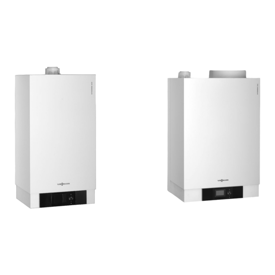
Viessmann VITODENS 200-W Technical Manual
Gas condensing boiler 3.8 to 35.0 kw
Hide thumbs
Also See for VITODENS 200-W:
- Installation and service instructions manual (188 pages) ,
- Installation instructions manual (184 pages) ,
- Service instructions manual (150 pages)
Table of Contents
Advertisement
VIESMANN
Technical guide
VITODENS 200-W
Wall mounted gas condensing boiler,
4.8 to 35.0 kW,
for natural gas and LPG
VITODENS 222-W
Compact gas condensing boiler,
4.8 to 35.0 kW,
for natural gas and LPG
VITODENS 300-W
Wall mounted gas condensing boiler,
3.8 to 35.0 kW,
for natural gas and LPG
5822 430 GB
5/2010
Type WB2C
Type WS2B
Type WB3D
VITODENS
Gas condensing boiler
3.8 to 35.0 kW
Advertisement
Table of Contents

Related Manuals for Viessmann VITODENS 200-W


Summary of Contents for Viessmann VITODENS 200-W
- Page 1 VIESMANN VITODENS Gas condensing boiler 3.8 to 35.0 kW Technical guide VITODENS 200-W Type WB2C Wall mounted gas condensing boiler, 4.8 to 35.0 kW, for natural gas and LPG VITODENS 222-W Type WS2B Compact gas condensing boiler, 4.8 to 35.0 kW,...
-
Page 2: Table Of Contents
■ Self-supporting installation of the Vitodens 200-W and 300-W ......... 57 ■ Pre-installation of the Vitodens 222-W ..............58 6.2 Replacement of third party appliances with the Vitodens 200-W and 300-W ....60 ■ Replacing a Ceramini-Z-SR with a Vitodens 200-W (4.8-19 kW) or a Vitodens 300- W (3.8-19 kW) ...................... - Page 3 Index (cont.) 6.4 Connections on the water side ..................69 ■ Connections on the DHW side .................. 69 6.5 Condensate connection ....................72 ■ Condensate drain and neutralisation ................ 72 6.6 Hydraulic connection ....................74 ■ General ........................74 ■ Expansion vessels ....................74 ■...
-
Page 4: Vitodens 200-W 1.1 Product Description
Stainless steel is the only choice of material where economy and a – as a combi boiler: 6.5 to 35.0 kW long service life are required. For this reason, the Vitodens 200-W is ■ Standard seasonal efficiency [to DIN]: up to 98 % (H )/109 % (H equipped with a stainless steel Inox-Radial heat exchanger. - Page 5 Vitodens 200-W (cont.) Delivered condition ■ With boiler drain & fill valve Wall mounted gas condensing boiler with Inox-Radial heat exchanger, ■ With gas shut-off valve with thermally activated safety shut-off valve. modulating MatriX cylinder burner for natural gas and LPG to DVGW Code of Practice G260 [Germany], Aqua-plate with multi-connect sys- For installation either on finished or unfinished walls.
-
Page 6: Specification
Vitodens 200-W (cont.) 1.2 Specification Gas boiler, series B and C, Gas boiler Gas combi boiler Category II 2N3P Rated output range (details to EN 677) = 50/30 °C 4.8-19.0 6.5-26.0 8.8-35.0 6.5-26.0 8.8-35.0 = 80/60 °C 4.3-17.2 5.9-23.7 8.0-31.7 5.9-23.7... - Page 7 Vitodens 200-W (cont.) Gas boiler, series B and C, Gas boiler Gas combi boiler Category II 2N3P Rated output range (details to EN 677) = 50/30 °C 4.8-19.0 6.5-26.0 8.8-35.0 6.5-26.0 8.8-35.0 = 80/60 °C 4.3-17.2 5.9-23.7 8.0-31.7 5.9-23.7 8.0-31.7...
- Page 8 55. Note Route all required supply cables on site and lead them into the boiler at the point indicated (see page 51). Two-stage heating circuit pump in the Vitodens 200-W Rated boiler output 4.8 - 19.0 6.5 - 26.0 8.8 - 35.0...
- Page 9 Vitodens 200-W (cont.) Residual head of the integral circulation pump Vitodens 200-W, 4.8 - 19.0 kW 1000 1100 1200 1300 1400 Flow rate in l/h A Stage 1 B Stage 2 C Upper operational limit Vitodens 200-W, 6.5 - 26.0 kW...
- Page 10 A Stage 1 B Stage 2 C Upper operational limit Variable speed heating circuit pump in the Vitodens 200-W The integral circulation pump is a highly efficient DC pump with more Circulation pump VI UPM-15-70 KM than 50 % less power consumption than conventional pumps.
- Page 11 Vitodens 200-W (cont.) Residual head of the integral circulation pump Vitodens 200-W, 4.8 - 26.0 kW 1000 1100 1200 1300 1400 Flow rate in l/h E Upper operational limit Curve Circulation pump rate Setting code address "E6" 30 % E6:030...
- Page 12 Vitodens 200-W (cont.) Vitodens 200-W, 8.8 - 35.0 kW 900 1000 1100 1200 1300 1400 1500 Flow rate in l/h G Upper operational limit Curve Circulation pump rate Setting code address "E6" 30 % E6:030 50 % E6:050 60 %...
- Page 13 Volume flow at the tap (mixed water volume) in l/min A DHW outlet temperature at the mixer B Vitodens 200-W, 6.5 to 26 kW C Vitodens 200-W, 8.8 to 35 kW The diagram illustrates the changes in the outlet temperature, subject The illustrated outlet temperature characteristics are based on a cold to the flow rate at the tap.
-
Page 14: Vitodens 222-W 2.1 Product Description
Vitodens 222-W 2.1 Product description A Inox-Radial heat exchangers made from stainless steel - for high operational reliability, a long service life and high output on the smallest footprint B Primary store made from stainless steel C Modulating MatriX cylinder burner with intelligent Lambda Pro Control combustion controller for clean combustion and quiet operation D Integral diaphragm expansion vessel... - Page 15 Vitodens 222-W (cont.) Accessories required (order separately) Approved quality CE designation according to current EC Directives Installation aid: Qualitätsmarke der ÖVGW gem. Gütezeichenverordnung ■ With fixing elements 1942 DRGBl. I für Erzeugnisse des Gas- und Wasserfachs ■ With fittings Meets the requirements for the "Blue Angel" certificate of environmen- ■...
-
Page 16: Specification
Vitodens 222-W (cont.) 2.2 Specification Gas boiler, series B and C, Category II 2N3P Rated output range (details to EN 677) = 50/30 °C 4.8-19.0 6.5-26.0 8.8-35.0 = 80/60 °C 4.3-17.2 5.9-23.7 8.0-31.7 Rated output range for DHW heating 4.3-17.2 5.9-29.3 8.0-35.0 Rated heat input... - Page 17 Vitodens 222-W (cont.) Gas boiler, series B and C, Category II 2N3P Rated output range (details to EN 677) = 50/30 °C 4.8-19.0 6.5-26.0 8.8-35.0 = 80/60 °C 4.3-17.2 5.9-23.7 8.0-31.7 Flue gas parameters Flue gas value group to G 635/G 636 Temperature (at 30 °C return temperature) –...
- Page 18 Vitodens 222-W (cont.) Condensate drain Heating flow Drain KW Cold water Gas connection SIV Safety valve on the DHW side Heating return WW Domestic hot water Rated output Dimension a Finished wall 4.8 - 19.0 6.5 - 35.0 Note For connection dimensions for installation on finished walls with instal- lation aid, see page 58.
- Page 19 Vitodens 222-W (cont.) Residual head of the integral circulation pump Vitodens 222-W, 4.8 - 26.0 kW 1000 1100 1200 1300 1400 Flow rate in l/h A Stage 1 B Stage 2 C Upper operational limit Vitodens 222-W, 8.8 - 35.0 kW 1000 1100 1200 1300 1400 Flow rate in l/h...
- Page 20 Vitodens 222-W (cont.) Circulation pump VI UPM-15-70 KM Rated voltage Power consumption max. min. Power consumption in the delivered condition - 4.8-19 kW - 6.5-26 kW - 8.8-35 kW Residual head of the integral circulation pump Vitodens 222-W, 4.8 - 26.0 kW 1000 1100 1200...
- Page 21 Vitodens 222-W (cont.) Vitodens 222-W, 8.8 - 35.0 kW 900 1000 1100 1200 1300 1400 1500 Flow rate in l/h G Upper operational limit Curve Circulation pump rate Setting code address "E6" 30 % E6:030 50 % E6:050 60 % E6:060 70 % E6:070...
-
Page 22: Vitodens 300-W 3.1 Product Description
Vitodens 300-W 3.1 Product description A Modulating MatriX gas burner with intelligent Lambda Pro Control combustion controller for extremely clean combustion and quiet operation B Inox-Radial heat exchangers made from stainless steel - for high operational reliability, a long service life and high output on the smallest footprint C Variable speed combustion fan for quiet and economical opera- tion... - Page 23 Vitodens 300-W (cont.) Accessories required (order separately) Vitodens installation in front of a wall Vitodens installation directly onto a wall Self-supporting mounting frame (depth 110 mm): ■ With fixing elements Installation aid: ■ With fittings ■ With fixing elements ■ With boiler drain & fill valve ■...
-
Page 24: Specification
Vitodens 300-W (cont.) 3.2 Specification Gas boiler, types B and C, category II Gas boiler 2N3P Rated output range (details to EN 677) = 50/30 °C 3.8-13.0 3.8-19.0 5.2-26.0 7.0-35.0 = 80/60 °C 3.5-11.8 3.5-17.2 4.7-23.7 6.4-32.0 Rated output for DHW heating 3.5-16.0 3.5-17.2 4.7-23.7... - Page 25 Vitodens 300-W (cont.) Gas boiler, types B and C, category II Gas boiler 2N3P Rated output range (details to EN 677) = 50/30 °C 3.8-13.0 3.8-19.0 5.2-26.0 7.0-35.0 = 80/60 °C 3.5-11.8 3.5-17.2 4.7-23.7 6.4-32.0 Internal diameter of pipe to expansion vessel –...
- Page 26 Vitodens 300-W (cont.) Vitodens 300-W, 5.2 to 35 kW HV GA HR HV GA HR OKFF OKFF Compulsory in conjunction with DHW cylinders, below. Other- Heating return wise, recommendation only. Heating flow Installation on finished walls Boiler flue connection Installation on unfinished walls OKFF Top edge finished floor Safety valve Expansion vessel connection G ¾...
- Page 27 Vitodens 300-W (cont.) Circulation pump UPM 15 Rated output range in kW Speed settings in the delivered condition in % Rated voltage Power consumption max. 3.8-13 min. 3.8-19 in the delivered condition 5.2-26 – 3.8-13 kW 7.0-35 – 3.8-19 kW –...
- Page 28 Vitodens 300-W (cont.) Vitodens 300-W, 5.2-35 kW 1000 1100 1200 1300 1400 Flow rate in l/h K Upper operational limit Curve Circulation pump rate Setting code address "E6" 30 % E6:030 40 % E6:040 50 % E6:050 60 % E6:060 70 % E6:070 80 %...
-
Page 29: Separate Dhw Cylinders 4.1 Vitocell 100-W (Type Cug – 120 And 150 Litres), Below Made From Steel With Cerapro Tect Enamel Coating
Separate DHW cylinders 4.1 Vitocell 100-W (type CUG – 120 and 150 litres), below made from steel with Ceraprotect enamel coating ■ Below the boiler ■ Made from steel, with Ceraprotect enamel coating and internal indirect coils Capacity DIN register no. 0245/06-13 MC with casing to cover with casing to cover... -
Page 30: Delivered Condition
Separate DHW cylinders (cont.) Dimensions Capacity 120 l 150 l Without casing with casing to cover Without casing with casing to cover connecting pipes connecting pipes connecting pipes connecting pipes 1055 1055 Ø 553 Ø 596 2079 2079 2079 2079 2149 2149 2149... - Page 31 Separate DHW cylinders (cont.) DHW cylinder made from steel with Ceraprotect enamel coating. ■ Protective magnesium anode ■ Welded sensor well for cylinder temperature sensor ■ Fitted thermal insulation made from rigid PU foam ■ Threaded adjustable feet The colour of the epoxy-coated sheet steel casing is white. VIESMANN VITODENS...
-
Page 32: Vitocell 100-W, Adjacent, (Type Cva – 160, 200 And 300 Litres, White Finish) Made From Steel With Ceraprotect Enamel Coating
Separate DHW cylinders (cont.) 4.2 Vitocell 100-W, adjacent, (type CVA – 160, 200 and 300 litres, white finish) made from steel with Ceraprotect enamel coating ■ Adjacent ■ made from steel, with Ceraprotect enamel coating and internal indirect coils (for further technical details, see the separate datasheet for the Vitocell 100-V) Capacity DIN register no. - Page 33 Separate DHW cylinders (cont.) Dimensions Cylinder capacity 7 581 7 581 7 633 1189 1409 1746 1050 1270 1600 1115 – – 7 100 – – Pressure drop on the DHW side 1000 DHW volume in litres/h A 160 and 200 litres B 300 litres DHW output at rated boiler output Rated output for DHW heating...
-
Page 34: Delivered Condition
Separate DHW cylinders (cont.) Rated output for DHW heating Performance factor N to DIN 4708 Cylinder capacity 160 l Cylinder capacity 200 l Cylinder capacity 300 l Peak output over a 10 minute period Cylinder capacity 160 l l/10 min Cylinder capacity 200 l l/10 min Cylinder capacity 300 l... -
Page 35: Vitocell 300-W, Adjacent (Type Eva – 160 And 200 Litre, White Finish), With Peripheral Indirect Coil, Made From Stainless Steel
Separate DHW cylinders (cont.) 4.3 Vitocell 300-W, adjacent (type EVA – 160 and 200 litre, white finish), with peripheral indirect coil, made from stainless steel ■ Adjacent ■ Made from stainless steel, with external indirect coils (for further technical details, see the separate datasheet for the Vitocell 300-V) Capacity DIN register no. -
Page 36: Delivered Condition
Separate DHW cylinders (cont.) Dimensions Cylinder capacity 7 633 7 633 1203 1423 1067 1287 1204 1097 Pressure drop on the DHW side DHW volume in litres/h DHW output at rated boiler output Rated output for DHW heating Continuous DHW output for DHW heating from 10 to 45 ºC and an average boiler water temperature of 70 °C Cylinder capacity 160 l... -
Page 37: Vitocell 100-W, Adjacent (Type Cvb – 300 And 400 Litres, White Finish), Made From Steel With Ceraprotect Enamel Coating For Dual Mode Dhw Heating
Separate DHW cylinders (cont.) 4.4 Vitocell 100-W, adjacent (type CVB – 300 and 400 litres, white finish), made from steel with Ceraprotect enamel coating for dual mode DHW heating ■ Adjacent ■ made from steel, with Ceraprotect enamel coating and internal indi- rect coils ■... - Page 38 Separate DHW cylinders (cont.) Dimensions Cylinder capacity 7 633 7850 1746 1630 1600 1458 1355 1204 1115 1044 7 100 7 100 Recommended arrangement of the cylinder temperature sensor for solar operation A Cylinder temperature sensor (solar control unit) B Threaded elbow with sensor well (standard delivery) Pressure drop on the DHW side DHW throughput in litres/h...
-
Page 39: Delivered Condition
Separate DHW cylinders (cont.) DHW output at rated boiler output Rated output for DHW heating Continuous DHW output for DHW heating from 10 to 45 ºC and an average boiler water temperature of 78 °C Performance factor N to DIN 4708 Peak output l/10 min over a 10 minute period... -
Page 40: Vitocell 100-W, Adjacent (Type Cvua – 300 Litres, White Finish), Made From Steel With Ceraprotect Enamel Coating For Dual Mode Dhw Heating
Separate DHW cylinders (cont.) 4.5 Vitocell 100-W, adjacent (type CVUA – 300 litres, white finish), made from steel with Ceraprotect enamel coating for dual mode DHW heating ■ Adjacent ■ Made from steel, with Ceraprotect enamel coating and internal indi- rect coils ■... -
Page 41: Delivered Condition
Separate DHW cylinders (cont.) Dimensions Pressure drop on the DHW side Dimensions Dimensions in mm 1705 DHW throughput in l/h DHW output at rated boiler output Rated output for DHW heating Continuous DHW output for DHW heating from 10 to 45 ºC and an average boiler water temperature of 78 °C Performance factor N... -
Page 42: Installation Accessories 5.1 Installation Accessories For The Vitodens 200-W And 300-W
Installation with a sub-mounting kit Installation on finished walls with gas condensing boiler or gas con- Comprising: densing combi boiler (for the Vitodens 200-W and Vitodens 300-W ■ Plate heat exchanger for system separation of the heating circuit with only). - Page 43 Comprising: below. The heating circuit without mixer is supplied by the integral circulation pump of the Vitodens 200-W or 300-W. For installation design regard- ing operation with the sub-mounting kit, see "System examples". Gas connection Rp ½ HV1 Heating flow, heating circuit without mixer R ¾...
- Page 44 Max. power consumption (total) – with 3-stage circulation pump – With variable speed high efficiency DC pump W Dimension a – Vitodens 200-W, 19 to 35 kW and 300-W to 19 kW – Vitodens 300-W, 26 and 35 kW Weight (incl. packaging)
-
Page 45: Installation With Mounting Frame
Installation accessories (cont.) Calculating the transferable output (examples) Example: The sub-mounting kit is equipped with an integral balancing valve. This enables the flow rate via the plate heat exchanger to the regulated Vitodens 300-W, 5.2 -26 kW heating circuit to be restricted as required. ■... -
Page 46: Additional Accessories
Additional accessories Safety assembly to DIN 1988 Valve/fittings cover Comprising: ■ For the Vitodens 200-W and the Vitodens 300-W, 3.8 to 19 kW ■ Shut-off valve Part no. 7438 096 ■ Non-return valve and test connector ■ For the Vitodens 300-W, 5.2 to 35 kW ■... -
Page 47: Connection Between The Vitodens And The Dhw Cylinder
Zero volt contact N/C, breaking capacity 230 VA Plate heat exchanger flushing system Part no. 7373 005 For Vitodens 200-W, 6.5 to 35 kW. Small softening system for heating water For filling heating circuits. See Vitoset pricelist. A Condensate inlet... -
Page 48: Installation Accessories For The Vitodens 222-W
Installation accessories (cont.) 5.2 Installation accessories for the Vitodens 222-W Installation aid for finished walls ■ Diaphragm safety valve 10 bar Part no. 7248 408 ■ a Diaphragm safety valve 6 bar Part no. 7248 406 Comprising: ■ Fixing elements ■... -
Page 49: Flue Gas Cascade (Positive Pressure) For Multi-Boiler Systems With Vitodens 200-W And 222-W
■ Non-return valve A Condensate inlet B Condensate inlet with drain plug C Condensate drain Flue gas cascade (positive pressure) for multi-boiler systems with Vitodens 200-W and 222-W Comprising: ■ Flue gas non-return device for each boiler ■ Flue gas header ■... -
Page 50: Design Information 6.1 Positioning, Installation
Installation accessories (cont.) ■ Two-boiler system – 19 and 26 kW: Part no. Z008 384 – 35 kW: Part no. Z008 385 ■ Three-boiler system – 19 to 35 kW: Part no. Z008 386 ■ Four-boiler system – 19 to 35 kW: Part no. Z008 387 A Flue gas header B Flue gas non-return device (for installation in the Vitodens) C Terminal with siphon... -
Page 51: Operation Of The Vitodens In Wet Areas
Design information (cont.) It may, for example, be installed in recreation rooms, in other living Electrical interlocks for extractors (extractor hoods, etc.) are not space, in ancillary rooms without ventilation, in cupboards (open at the required with balanced flue operation. top) and recesses without maintaining minimum clearances to com- bustible parts as well as in attic rooms (pitched attics and ancillary Installation in a garage... -
Page 52: Gas Connection
Design information (cont.) Vitodens 200-W and 300-W A Reference point Vitodens top edge Vitodens 222-W B Area for electrical supply cables A Reference point Vitodens top edge B Area for electrical supply cables Recommended leads/cables NYM 3 G 1.5 mm 2-core min. -
Page 53: Minimum Clearances
Maintenance clearances to the l.h. or r.h. side of the Vitodens are cylinder for maintenance purposes. not required. Pre-installation for mounting the Vitodens 200-W and 300-W directly on the wall – Installation on finished walls Accessories required for installation without DHW cylinder... -
Page 54: Pre-Installation With The Sub-Mounting Kit With Mixer – Installation On Finished Walls
Design information (cont.) SVL/WW SRL/KW Vitodens Gas connection Rp ½ Installation aid Heating return Rp ¾ Area for electrical supply cables. Heating flow Rp ¾ Cold water Rp ½ (gas combi boiler) Allow all cables/leads to protrude approx. 800 mm from the wall. -
Page 55: Pre-Installation For Mounting The Vitodens 200-W And 300-W Directly On The Wall – Installation On Unfinished Walls
Sub-mounting kit cover Cylinder flow G ¾ (gas boiler) Gas connection R ½ Pre-installation for mounting the Vitodens 200-W and 300-W directly on the wall – Installation on unfinished walls Accessories required for installation without DHW cylinder Additional requirements when connecting a DHW cylinder Connection set for DHW cylinders. -
Page 56: Pre-Installation With Mounting Frame
Design information (cont.) SRL/KW SVL/WW Illustration: Gas boiler connections Vitodens Drain Installation aid Gas connection R ½ Heating return G ¾ Area for electrical supply cables. Allow all cables/leads to protrude approx. 800 mm from the Heating flow G ¾ Cold water G ½... -
Page 57: Self-Supporting Installation Of The Vitodens 200-W And 300-W
Compulsory in conjunction with DHW cylinders, below. Other- Cylinder return G ¾ Cylinder flow G ¾ wise, recommendation only. Self-supporting installation of the Vitodens 200-W and 300-W Self-supporting mounting frame ■ For gas combi boiler Suitable for wall mounting, for self-supporting installation or cover- ■... -
Page 58: Pre-Installation Of The Vitodens 222-W
Design information (cont.) Self-supporting mounting frame for the Vitodens with connection Gas connection R ½ panel Heating return G ¾ Ceiling fixing extension (Vitodens) Heating flow G ¾ KW Cold water G ½ (gas combi boiler) Vitodens Gas combi boiler connection panel WW DHW G ½... - Page 59 Design information (cont.) Installation aid Gas connection R ½ Heating return R ¾ Vitodens position Area for electrical supply cables. Heating flow R ¾ KW Cold water R ½ Allow all cables/leads to protrude approx. 1300 mm from the SIV Safety valve on the DHW side wall.
-
Page 60: Replacement Of Third Party Appliances With The Vitodens 200-W And 300-W
WW Hot water R ½ Drain 6.2 Replacement of third party appliances with the Vitodens 200-W and 300-W Using an adaptor, the Vitodens hydraulic connections are compatible Match up the flue connections on site. with Ceramini-Z-SR, Cerastar-ZR/-ZWR and Thermoblock-VC110E-/ VC112E/-VC/-VCW boilers. -
Page 61: Replacing A Ceramini-Z-Sr With A Vitodens 200-W (4.8-19 Kw) Or A Vitodens
Design information (cont.) Replacing a Ceramini-Z-SR with a Vitodens 200-W (4.8-19 kW) or a Vitodens 300-W (3.8-19 kW) Open flue operation Ø 90 Ceramini Vitodens Dimen- Unfinished walls Finished walls sions 1098 1086 Balanced flue operation Ø 90 Ceramini Vitodens The parts marked in grey (incl. -
Page 62: Replacing A Cerastar-Zr/-Zwr With A Vitodens 200-W (6.5-35 Kw) Or A Vitodens 300-W (5.2-35 Kw)
Design information (cont.) Installation on unfinished walls Installation on finished walls Replacing a Cerastar-ZR/-ZWR with a Vitodens 200-W (6.5-35 kW) or a Vitodens 300-W (5.2-35 kW) Open flue operation Ø 112 Cerastar Vitodens VIESMANN VITODENS... - Page 63 Design information (cont.) Balanced flue operation Ø 112 Cerastar Vitodens Existing hydraulic connections have identical dimensions. The parts marked in grey (incl. mounting rail) in the following diagrams are part of the standard delivery. Installation on unfinished walls Gas combi boiler Installation on finished walls Gas boiler Gas boiler...
-
Page 64: Replacing A Thermoblock-Vc110E/-Vc112E With A Vitodens 200-W (4.8-19 Kw) Or A Vitodens 300-W (3.8-19 Kw)
Design information (cont.) Gas combi boiler Replacing a Thermoblock-VC110E/-VC112E with a Vitodens 200-W (4.8-19 kW) or a Vitodens 300-W (3.8-19 kW) Open flue operation Û Thermoblock Vitodens VC 110E Dimen- Unfinished walls Finished walls sions 1037 1076 VIESMANN VITODENS... - Page 65 Design information (cont.) Balanced flue operation Thermoblock Vitodens VC 112E Dimen- Unfinished walls Finished walls sions 1044 1083 Existing hydraulic connections have identical dimensions. The parts marked in grey (incl. mounting rail) in the following diagrams Installation on finished walls are part of the standard delivery.
-
Page 66: Replacing A Thermoblock-Vc/-Vcw With A Vitodens 200-W (6.5-35 Kw) Or A Vitodens 300-W (5.2-35 Kw)
Design information (cont.) Replacing a Thermoblock-VC/-VCW with a Vitodens 200-W (6.5-35 kW) or a Vitodens 300-W (5.2-35 kW) Open flue operation Vitodens Thermoblock Balanced flue operation Vitodens Thermoblock Dimen- Unfinished walls Finished walls sions 1059 1098 Existing hydraulic connections have identical dimensions. -
Page 67: Decision-Making Aids Regarding Dhw Heating
DHW cylinder or an integral DHW primary gral DHW primary store (Vitodens 222-W): store: ■ Vitodens 200-W ■ DHW demand, convenience as a gas boiler and gas combi boiler ■ Utilisation of the various connected draw-off points ■... -
Page 68: Separate Dhw Cylinders
If identical consumers are combined with each other, only the individ- Note ual consumer will be considered and not the combination. Instead of a Vitodens 200-W or 300-W with 120 litre DHW cylinder, a The following summary enables the approximate sizing of the DHW Vitodens 222-W can also be used. -
Page 69: Selection Tables, Dhw Cylinders
The appliances with a "-B" or "-V" in the product name are sup- plied in Vitosilver (marked in grey in the table). Vitodens 200-W and 300-W gas boilers, cylinder allocation Practical cylinder allocation (cylinder capacity in litres) Rated output range [kW] 3.8 to 19.0... - Page 70 Design information (cont.) Cold water installation for the Vitodens 200-W gas combi boiler Install a safety valve if the cold water supply is equipped with a non- return valve. In addition remove the handle from the cold water shut off-valve.
- Page 71 DIN 1988, to prevent contaminants entering the DHW system. DHW circulation (only in conjunction with the Vitodens 200-W and 300-W) DHW circulation pipes increase DHW convenience and reduce water consumption.
-
Page 72: Condensate Connection
Design information (cont.) Vitodens 200-W and 300-W DHW cylinder, adjacent DHW cylinder, below A Domestic hot water A Domestic hot water B Cold water B Cold water C DHW circulation C DHW circulation Vitodens 222-W The connection of a DHW circulation line is not recommended. - Page 73 Design information (cont.) The consistency of condensate drained from Vitodens condensing The Vitodens can (if required) be supplied with a separate neutralising boilers meets the requirements specified in the Code of Practice ATV- system (accessories). Any condensate is piped to and treated in the DVWK-A 251.
-
Page 74: Hydraulic Connection
Plastic pipework for radiators Installation examples We also recommend the installation of a temperature limiter to restrict For installation examples for the Vitodens 200-W, 222-W and 300-W, the maximum temperature of plastic pipes in heating circuits with radi- see "System examples". -
Page 75: Low Loss Header
= 9.32 litres ted to the mounting frame Result: The integral expansion vessel (10 litre capacity) is sufficiently large for this system. Expansion vessel integrated into the Vitodens 200-W, Vitodens 222-W and Vitodens 300-W, 13 and 19 kW Note Pre-charge 0.75 bar... - Page 76 Suitable thermometers in the flow and return of the low loss header make adjustments easier. Low loss header in conjunction with Divicon For further details, see the technical guide to the Vitodens 200-W, 45 HR Heating return to 105 kW.
-
Page 77: Control Units 7.1 Vitotronic 100, Type Hc1A, For Constant Temperature Operation
■ User prompts through pictograms ■ Control keys for: Specification – Navigation Sensor type Viessmann NTC, 10 kΩ at – Confirmation 25 °C – Adjustments/menu Permissible ambient temperature ■ Setting the: – during operation 0 to +130 °C... -
Page 78: Specification Vitotronic 100, Type Hc1A
Control units (cont.) Permissible ambient temperature – during operation 0 to +90 °C – during storage and transport –20 to +70 °C Specification Vitotronic 100, type HC1A Rated voltage 230 V~ Electronic tempera- Rated frequency 50 Hz ture limiter setting Rated current (heating mode) 82 °C (change not possible) - Page 79 -20 to +70 °C the boiler water is maintained at a lower temperature of approx. 20 °C. Cylinder temperature sensor (Vitodens 200-W and 300-W) The DHW cylinder will be heated to approx. 20°C. Standard delivery for: ■ The frost protection function will be stopped when the outside tem- ■...
-
Page 80: Specification Vitotronic 200, Type Ho1A
Specification IP rating IP 43 to EN 60529; ensure through appropri- ate design/installation Sensor type Viessmann NTC 10 kΩ at 25 °C Permissible ambient temperature during operation, storage and transport -40 to +70 °C Specification Vitotronic 200, type HO1A Rated voltage... -
Page 81: Vitotrol 100, Type Uta
Control units (cont.) Vitotronic Type HC1A HO1A Accessories Extension AM1 Extension EA1 Vitotrol 100, type UTA Part no. 7170 149 Specification Rated voltage 230 V/50 Hz Room thermostat Rated breaking capacity of the con- ■ With switching output (two-point output) tact 6(1) A 250 V~ ■... -
Page 82: External Extension H4
Control units (cont.) Permissible ambient temperature Setting range – during operation 0 to +40 °C – Comfort temperature 10 to 40 °C – during storage and transport –25 to +65 °C – Setback temperature 10 to 40 °C – Frost protection temperature 5 °C Power reserve during battery change... -
Page 83: Notes Regarding Room Temperature Hook-Up (Rs Function) For Remote Control Units
Control units (cont.) Specification, receiver Protection class II to EN 60730-1 subject to cor- Operating voltage 230 V~ ± 10 % 50 Hz rect installation Rated breaking capacity of the zero Permissible ambient temperature volt contact – during operation 0 to +40 °C –... -
Page 84: Room Temperature Sensor
Installation in the main living room on an internal wall opposite radia- Sensor type Viessmann NTC 10 kΩ at 25 °C tors. Never install inside shelving units, in niches, or immediately by a Permissible ambient temperature door or heat source (e.g. direct sunlight, fireplace, TV set, etc.). -
Page 85: Radio Clock Receiver
■ Power cable (3.0 m long) ■ BUS cable (3.0 m long) Components: ■ Mixer PCB with mixer motor for Viessmann mixer DN 20 to 50 and The mixer motor is mounted directly onto the Viessmann mixer DN 20 R ½ to 1¼... -
Page 86: Extension Kit For One Heating Circuit With Mixer For Separate Mixer Motor
Power consumption 5.5 W design/installation IP rating IP 32D to EN 60529 Sensor type Viessmann NTC 10 kΩ at ensure through appropriate 25 °C design/installation Permissible ambient temperature Protection class – during operation 0 to +120 °C Permissible ambient temperature –... -
Page 87: Immersion Thermostat
Specification IP rating IP 32D to EN 60529 ensure through appropriate design/installation Sensor type Viessmann NTC 10 kΩ at 25 °C Permissible ambient temperature – during operation 0 to +120 °C – during storage and transport –20 to +70 °C Immersion thermostat Part no. -
Page 88: Solar Control Module, Type Sm1
– during storage and transport ■ For DHW circulation diversion for systems with 2 DHW cylinders For systems with Viessmann DHW cylinders, the cylinder temperature ■ for return changeover between the boiler and the heating water buf- sensor is installed in the threaded elbow (see chapter "Specification"... -
Page 89: Lon Communication Module
Control units (cont.) LON communication module PCB for data exchange with the Vitotronic 200-H, Vitocom 200 and for Part no. 7179 113 connecting to a higher level building management system. LON connecting cable for data exchange between control units Part no. 7143 495 Cable length 7 m, fully wired. -
Page 90: Immersion Temperature Sensor
– Connection of an external safety solenoid valve (LPG) 1(0.5) A 250 V~ and one of the following functions (only for Vitodens 200-W and 300-W): 2(1) A 250 V~ – Connection of a heating circuit pump (stepped) for a directly connected heating circuit –... -
Page 91: Extension Ea1
The design and operational characteristics of the Vitodens gas con- Observe all standards and guidelines applicable to the installation and densing boilers from Viessmann meet the requirements of EN 297. operation of this system in your country. They are CE-designated. - Page 92 Appendix (cont.) In some regions, permits may be required for the flue system and con- Condensing boilers must only be operated with specially designed, densate drain into the public sewer. tested and approved flue pipes. In some countries, the relevant flue gas inspector and water authorities Only recognised contractors may convert this boiler for use in countries must be informed prior to commencing the installation.
-
Page 93: Keyword Index
Keyword index Accessories KM BUS distributor................89 ■ for installation................42 Anti-corrosion agents...............74 Antifreeze..................74 Leads/cables..................52 Anti-water hammer device...............70 Level....................79 LON communication module............89 Low loss header................75 Balanced flue operation..............50 Low water indicator................74 Boiler water temperature sensor..........77, 79 Mixer extension Comfort function................12 ■ Integral mixer motor..............85 Condensate..................73 ■... - Page 94 Keyword index Vitocell 100-W..............29, 32, 37, 40 Water quality..................74 Vitocell 100-W, adjacent Weather-compensated control ■ Pressure drop on the DHW side..........33, 38 ■ Operating programs..............79 Vitocell 300-W..................35 Weather-compensated control unit Vitocell 300-W, adjacent ■ Frost protection function...............79 ■ Pressure drop on the DHW side...........36 ■...
- Page 95 VIESMANN VITODENS...
- Page 96 Subject to technical modifications. Viessmann Werke GmbH&Co KG Viessmann Limited D-35107 Allendorf Hortonwood 30, Telford Telephone: +49 6452 70-0 Shropshire, TF1 7YP, GB Fax: +49 6452 70-2780 Telephone: +44 1952 675000 www.viessmann.com Fax: +44 1952 675040 E-mail: info-uk@viessmann.com VIESMANN VITODENS...