Table of Contents
Advertisement
Quick Links
A detailed guide to the FortiGate-5001FA2-LENC Security System. This FortiGate-5001FA2-LENC Security System
Guide describes FortiGate-5001FA2-LENC hardware features, how to install the FortiGate-5001FA2-LENC board in
a FortiGate-5000 series chassis, how to configure the FortiGate-5001FA2-LENC security system for your network,
and contains troubleshooting information to help you diagnose and fix problems.
The most recent versions of this and all FortiGate-5000 series documents are available from the
page of the
Fortinet Technical Documentation
Visit
http://support.fortinet.com
FortiGate-5001FA2-LENC Security System Guide
01-30000-76602-20080606
S e c u r i t y S y s t e m G u i d e
FortiGate-5001FA2-LENC
web site (http://docs.forticare.com).
to register your FortiGate-5001FA2-LENC system. By registering you can receive
product updates, technical support, and FortiGuard services.
www.fortinet.com
FortiGate-5000
Advertisement
Table of Contents

Related Manuals for Fortinet FortiGate 5001FA2-LENC


Summary of Contents for Fortinet FortiGate 5001FA2-LENC
- Page 1 The most recent versions of this and all FortiGate-5000 series documents are available from the page of the Fortinet Technical Documentation Visit http://support.fortinet.com product updates, technical support, and FortiGuard services.
-
Page 2: Warnings And Cautions
Some FortiGate-5000 series components may overload your supply circuit and impact your overcurrent protection and supply wiring. Refer to nameplate ratings to address this concern. • Make sure all FortiGate-5000 series components have reliable grounding. Fortinet recommends direct connections to the branch circuit. •... -
Page 3: Table Of Contents
Troubleshooting ... 18 FortiGate-5001FA2-LENC does not startup ... 18 FortiGate-5001FA2-LENC cannot display chassis information ... 20 Quick Configuration Guide ... 21 Registering your Fortinet product ... 21 Upgrading to High Encryption... 21 Planning the configuration ... 22 NAT/Route mode ... 22 Transparent mode ... - Page 4 Powering off the FortiGate-5001FA2-LENC board ... 32 Fortinet documentation ... 33 Fortinet Tools and Documentation CD... 33 Fortinet Knowledge Center ... 33 Comments on Fortinet technical documentation ... 33 Customer service and technical support ... 33 Register your Fortinet product... 33 FortiGate-5001FA2-LENC Security System Guide...
-
Page 5: Fortigate-5001Fa2-Lenc Security System
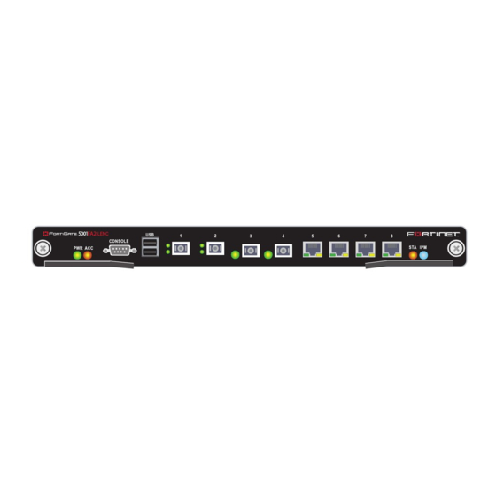
FortiGate-5001FA2-LENC security system FortiGate-5001FA2-LENC security system The FortiGate-5001FA2-LENC security system is a high-performance FortiGate security system with a total of 8 front panel gigabit ethernet interfaces and two base backplane interfaces. Use the front panel interfaces for connections to your networks and the backplane interfaces for communication between FortiGate-5000 series boards over the FortiGate-5000 chassis backplane. -
Page 6: Front Panel Leds And Connectors
The front panel also includes the RS-232 console port for connecting to the FortiOS CLI and a USB port. The USB port can be used with a Fortinet USB key. For information about using the FortiUSB key, see the Firmware and FortiUSB Guide. -
Page 7: Connectors
FortiGate-5001FA2-LENC security system Table 1: FortiGate-5001FA2-LENC board LEDs (Continued) 5, 6, 7, 8 Connectors Table 2 Table 2: FortiGate-5001FA2-LENC connectors Connector Type 1 and 2 3 and 4 5, 6, 7, 8 CONSOLE DB-9 Accelerated packet forwarding and policy enforcement FortiGate-5001FA2-LENC Accelerated packet forwarding and policy enforcement results in accelerated small packet performance required for voice, video, and other multimedia streaming applications. -
Page 8: Fa2 Interfaces And Active-Active Ha Performance
Base backplane gigabit communication FA2 interfaces and active-active HA performance Base backplane gigabit communication • Session Oriented Traffic with long session lifetime, such as FTP sessions. Packet size does not affect performance for traffic with long session lifetime. For long sessions, processing that would otherwise be handled by the FortiGate-5001FA2-LENC CPUs is off-loaded to the acceleration module. -
Page 9: Hardware Installation
Hardware installation Hardware installation Before use, the FortiGate-5001FA2-LENC board must be correctly inserted into an Advanced Telecommunications Computing Architecture (ACTA) chassis such as the FortiGate-5140, FortiGate-5050, or FortiGate-5020 chassis. Before inserting the board into a chassis you should make sure RAM DIMMS are installed and FortiGate-5001FA2-LENC jumpers are set. -
Page 10: Installing Sfp Transceivers
Installing SFP transceivers Hardware installation Figure 2: Location of FortiGate-5001FA2-LENC RAM DIMM slots RAM DIMM slots Front Faceplate Insert each RAM DIMM perpendicular to the RAM DIMM slots. Push the DIMM firmly into place using the minimum amount of force required. When the DIMM is properly seated, the socket guide posts click into place. -
Page 11: Changing Fortigate-5001Fa2-Lenc Jumper Settings
For cage slots 3 to 8, turn each SFP transceiver over before sliding it into the cage slot until it locks into place. Changing FortiGate-5001FA2-LENC jumper settings The JP3 jumper on the FortiGate-5001FA2-LENC board is factory set by Fortinet into one of two positions (see •... - Page 12 Changing FortiGate-5001FA2-LENC jumper settings Normally, because the jumpers are factory set, you do not have to change them. However, if you are moving a FortiGate-5001FA2-LENC from a FortiGate-5140 or FortiGate-5050 to a FortiGate-5020 or the reverse, you need to move the JP3 jumper.
-
Page 13: Inserting A Fortigate-5001Fa2-Lenc Board Into A Chassis
Hardware installation To change or verify the JP3 jumper setting To complete this procedure, you need: • A FortiGate-5001FA2-LENC board • A tool for moving jumpers (optional) • An electrostatic discharge (ESD) preventive wrist strap with connection cord Caution: FortiGate-5001FA2-LENC boards must be protected from static discharge and physical shock. -
Page 14: Before Inserting The Fortigate-5001Fa2-Lenc Board In A Chassis
Inserting a FortiGate-5001FA2-LENC board into a chassis Before inserting the FortiGate-5001FA2-LENC board in a chassis Insertion procedure Figure 4: FortiGate-5001FA2-LENC mounting components Closed Alignment Pin Retention Lock Screw Handle Open Before installing the FortiGate-5001FA2-LENC board in a chassis you should verify that the RAM DIMMs are installed and the JP3 jumper is set correctly. - Page 15 Hardware installation • A FortiGate-5000 series chassis with an empty slot • An electrostatic discharge (ESD) preventive wrist strap with connection cord Caution: FortiGate-5001FA2-LENC boards must be protected from static discharge and physical shock. Only handle or work with FortiGate-5001FA2-LENC boards at a static-free workstation.
- Page 16 Inserting a FortiGate-5001FA2-LENC board into a chassis Turn both handles to their fully-closed positions. The handles should hook into the sides of the chassis slot. Closing the handles draws the FortiGate-5001FA2-LENC board into place in the chassis slot and into contact with the chassis backplane.
-
Page 17: Removing A Fortigate-5001Fa2-Lenc Board From A Chassis
Hardware installation Removing a FortiGate-5001FA2-LENC board from a chassis The following procedure describes how to correctly use the FortiGate-5001FA2-LENC mounting components shown in FortiGate-5001FA2-LENC board from a FortiGate-5000 series chassis slot. To remove a FortiGate-5001FA2-LENC board from a FortiGate-5000 series chassis FortiGate-5001FA2-LENC boards are hot swappable. -
Page 18: Troubleshooting
Troubleshooting Troubleshooting FortiGate-5001FA2-LENC does not startup Open the left and right handles to their fully open positions. Opening the handles slides the board a short distance out of the slot, disconnecting the board from the chassis backplane. The IPM LED turns blue. All other LEDs turn off. Alignment Pin Handle Handle... - Page 19 LEDs are off). If the shelf manager is not functioning normally, you can try removing it from the chassis and reinstalling it. If this does not solve the problem, contact Fortinet Technical Support. If the shelf manager has been removed from the chassis, you should re-install it. If you are planning on operating the chassis without a shelf manager, you can move the FortiGate-5001FA2-LENC JP3 jumper between pins 1 and 2.
-
Page 20: Fortigate-5001Fa2-Lenc Cannot Display Chassis Information
FortiGate-5000 Series Firmware and FortiUSB Guide. If this does not solve the problem, contact Fortinet Technical Support. FortiGate-5001FA2-LENC cannot display chassis information If the FortiGate-5001FA2-LENC board is installed in a FortiGate-5140 or 5050 chassis, if a shelf manager is operating in the chassis, and if the JP3 jumper is set between pins 2 and 3, the FortiGate-5001FA2-LENC board should be able to communicate with the chassis shelf manager. -
Page 21: Quick Configuration Guide
Register your product by visiting Registration. To register, enter your contact information and the serial numbers of the Fortinet products that you or your organization have purchased. You can register multiple Fortinet products in a single session without re-entering your contact information. -
Page 22: Planning The Configuration
Planning the configuration Planning the configuration NAT/Route mode Before beginning to configure your FortiGate-5001FA2-LENC security system, you need to plan how to integrate the system into your network. Your configuration plan depends on the operating mode that you select: NAT/Route mode (the default) or Transparent mode. -
Page 23: Transparent Mode
Quick Configuration Guide Transparent mode In Transparent mode, the FortiGate-5001FA2-LENC security system is invisible to the network. All of the FortiGate-5001FA2-LENC interfaces are connected to different segments of the same network. In Transparent mode you only have to configure a management IP address so that you can connect to the FortiGate-5001FA2-LENC security system to make configuration changes and so the FortiGate-5001FA2-LENC security system can connect to external services such as the FortiGuard Distribution Network (FDN). -
Page 24: Command Line Interface (Cli)
Factory default settings Command Line Interface (CLI) Factory default settings The CLI is a full-featured management tool. Use it to configure the administrator password, the interface addresses, the default gateway, and the DNS server addresses. Requirements: • The serial connector that came packaged with your FortiGate-5001FA2-LENC board. -
Page 25: Configuring Nat/Route Mode
Quick Configuration Guide Configuring NAT/Route mode Table 6 settings for the FortiGate-5001FA2-LENC security system. You can use one table for each board to configure. Table 6: FortiGate-5001FA2-LENC board NAT/Route mode settings Admin Administrator Password: port1 port2 Default Route DNS Servers Using the web-based manager to configure NAT/Route mode Connect port1 of the FortiGate-5001FA2-LENC board to the same hub or switch as the computer you will use to configure the FortiGate board. -
Page 26: Using The Cli To Configure Nat/Route Mode
Configuring NAT/Route mode Using the CLI to configure NAT/Route mode Set the addressing mode for the interface. (See the online help for information.) • For manual addressing, enter the IP address and netmask for the interface that you added to Table 6 on page •... -
Page 27: Configuring Transparent Mode
Quick Configuration Guide Configure the primary and secondary DNS server IP addresses to the settings that you added to config system dns Configure the default gateway to the setting that you added to config router static Configuring Transparent mode Table 7 settings. -
Page 28: Using The Cli To Configure Transparent Mode
Configuring Transparent mode Using the CLI to configure Transparent mode To switch from NAT/Route mode to transparent mode Go to System > Status and select the Change link beside Operation Mode: NAT. Set Operation Mode to Transparent. Set the Management IP/Netmask to the settings that you added to page Set the default Gateway to the setting that you added to To change the admin administrator password... -
Page 29: Upgrading Fortigate-5001Fa2-Lenc Firmware
Quick Configuration Guide Upgrading FortiGate-5001FA2-LENC firmware Fortinet periodically updates the FortiGate-5001FA2-LENC FortiOS firmware to include enhancements and address issues. After you have registered your FortiGate-5001FA2-LENC security system (see product” on page the support web site http://support.fortinet.com. Only FortiGate-5001FA2-LENC administrators (whose access profiles contain system read and write privileges) and the FortiGate-5001FA2-LENC admin user can change the FortiGate-5001FA2-LENC firmware. -
Page 30: Fortigate-5001Fa2-Lenc Base Backplane Data Communication
FortiGate-5001FA2-LENC base backplane data communication FortiGate-5001FA2-LENC base backplane data communication Enter the following command to copy the firmware image from the TFTP server to the FortiGate-5001FA2-LENC board: execute restore image <name_str> <tftp_ipv4> Where <name_str> is the name of the firmware image file and <tftp_ipv4> is the IP address of the TFTP server. - Page 31 Quick Configuration Guide In a FortiGate-5140 or FortiGate-5050 chassis, FortiGate-5001FA2-LENC base backplane communication requires one or two FortiSwitch-5003 boards. A FortiSwitch-5003 board installed in chassis slot 1 provides communication on the port9 interface. A FortiSwitch-5003 board installed in chassis slot 2 provides communication on the port10 interface.
-
Page 32: Powering Off The Fortigate-5001Fa2-Lenc Board
Powering off the FortiGate-5001FA2-LENC board Powering off the FortiGate-5001FA2-LENC board To avoid potential hardware problems, always shut down the FortiGate-5001FA2-LENC operating system properly before removing the FortiGate-5001FA2-LENC board from a chassis slot or before powering down the chassis. To power off a FortiGate-5001FA2-LENC board Shut down the FortiGate-5001FA2-LENC operating system: •... -
Page 33: For More Information
Fortinet Tools and Documentation CD All Fortinet documentation is available from the Fortinet Tools and Documentation CD shipped with your Fortinet product. The documents on this CD are current for your product at shipping time. For the latest versions of all Fortinet documentation see the Fortinet Technical Documentation web site at http://docs.forticare.com. - Page 34 © Copyright 2008 Fortinet, Inc. All rights reserved. No part of this publication including text, examples, diagrams or illustrations may be reproduced, transmitted, or translated in any form or by any means, electronic, mechanical, manual, optical or otherwise, for any purpose, without prior written permission of Fortinet, Inc.