Shure UHF WIRELESS User Manual
Hide thumbs
Also See for UHF WIRELESS:
- User manual supplement (38 pages) ,
- User manual supplement (8 pages) ,
- User manual supplement (20 pages)
Table of Contents
Advertisement
Advertisement
Table of Contents

Related Manuals for Shure UHF WIRELESS


Summary of Contents for Shure UHF WIRELESS
-
Page 2: Important Safety Instructions
WARNING: Voltages in this equipment are hazardous to life. No user-serviceable parts inside. Refer all servicing to qualified service personnel. The safety certifications do not apply when the operating voltage is changed from the factory setting. 2004, Shure Incorporated Printed in U.S.A. 27C8571 (Rev. 6) -
Page 3: Table Of Contents
ENGLISH TABLE OF CONTENTS SYSTEM DESCRIPTION ............SYSTEM FEATURES . -
Page 4: System Description
ENGLISH SYSTEM DESCRIPTION The Shure UHF Wireless microphone system is a frequency-agile diversity sys- tem operating in the UHF band. Both the receiver and the transmitter are synthesizer controlled via Phase Locked Loop (PLL) circuitry for clear, steady radio frequency (RF) signal. -
Page 5: System Components
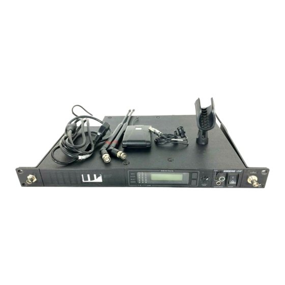
ENGLISH FIGURE 1 SYSTEM COMPONENTS (FIGURE 1) Each Shure UHF Wireless System includes the following components: U1 Body-Pack Transmitter with your choice of instrument cable or micro- phone, U2 Hand-Held Microphone-Transmitter with your choice of interchangeable microphone heads: • ... -
Page 6: U1 Body-Pack Transmitter Controls & Indicators
3. Input Connector: Provides connection with a variety of lavalier and headset mi- crophone cables, and the Shure WA302 instrument adapter cable. LEMO–type connectors are available as an option. 4. ON/OFF Switch: Turns transmitter power on and off. -
Page 7: U2 Microphone-Transmitter Controls & Indicators
ENGLISH GAIN FIGURE 3 U2 TRANSMITTER CONTROLS & INDICATORS (FIGURE 3) 1. Grille: Protects the microphone cartridge and helps reduce breath sounds and wind noise. The grilles for the various microphone heads differ in appearance. 2. Programmable Display: Displays Group and Channel, battery power level, and frequency lock/power lock on/off status. -
Page 8: U4S & U4D Receiver Controls & Connectors
ENGLISH U4S Receiver U4D Receiver FIGURE 4 U4S & U4D RECEIVER CONTROLS & CONNECTORS (FIGURE 4) 1. MENU Button: Press this button to access the main display menu. 2. SELECT Button: Press this button to choose or execute a displayed value or function. - Page 9 Hz power source. 14. Power Output Connector: Provides 90 to 230 VAC, 50/60 Hz power to additional equipment. It can be used to link multiple receivers or to power the Shure UA840 Antenna Distribution System. 15. Antenna Input Connectors: BNC-type connectors provide connection to the supplied antennas or to coaxial cable used with a distribution amplifier or remote antennas.
-
Page 10: Receiver Setup
ENGLISH RECEIVER SETUP Installing Rear Mounted Receiver Antennas Attach the supplied UHF antennas to the antenna BNC connectors on the receiver back panel, as shown in Figure 5. For best performance, orient the antennas with tips pointing away from each other at a 45° angle from vertical. FIGURE 5 Installing Front Mounted Receiver Antennas 1. - Page 11 Ñ Ñ Ñ Ñ Ñ Ñ Ñ Ñ Ñ Ñ Ñ Ñ Ñ FIGURE 7 NOTE: Shure recommends connecting the bulkhead adapter and antenna cables before mounting the receiver in a rack. Once the receiver is in the rack, it is more diffi- cult to insert the bulkhead adapters and connect the antenna cables.
-
Page 12: Basic Receiver Connections
ENGLISH Basic Receiver Connections (Figure 10) 1. Connect the receiver output to the mixer or amplifier input, using a standard audio cable with a female 3-pin XLR connector or -inch phone plug. 2. If desired, plug a set of headphones into the headphone monitor output connec- tor. -
Page 13: Viewing Current Receiver Settings
ENGLISH 3. Connect the female end of a modular power cord to the male power input connec- tor on the rear panel of the receiver. Then plug the power cord into a suitable AC power source. NOTE: If the receiver is rack-mounted, or if using front–mounted antennas, the antennas should extend above the rack cabinet or be remotely located. - Page 14 ENGLISH 4. Press the “SELECT” button to choose Group or Channel. The current Group, Channel, and TV channel setting appears, as shown in Figure 13. (Models sold out- side the U.S. and Canada may not display TV channel.) GROUP CHANNEL FIGURE 13 5.
-
Page 15: Changing Receiver Frequency Setting
ENGLISH Changing Receiver Frequency Setting 1. Press the MENU button. The “+ MENU –” display appears, as shown in Figure 16. FIGURE 16 2. Press either the + or – button to reach the SET FREQ display, shown in Figure 17. FIGURE 17 3. -
Page 16: Changing Receiver Name
FIGURE 22 3. Press the SELECT button. An underline appears under the first character of the name. The factory pre–set Name display (SHURE) is shown in Figure 23. FIGURE 23 4. Press either the + or – button to scroll through the character options (A–Z, 1–9, etc.) until reaching a desired character. -
Page 17: Changing Receiver Squelch Level Setting
ENGLISH 6. When the new name has been completely entered, press the MENU button. “SAVE?” appears, followed by “+ YES – NO”. Press the “+” button to save the new name and return to the Group/Channel/TV display. Press the “–” button to make more changes. - Page 18 ENGLISH NOTE: The highest possible squelch setting is +10.0 and the lowest possible squelch setting is –10.0, as shown in the following table . However, the factory preset level of 0.0 usually will not need to be changed.* Receiver Squelch Control Settings DISPLAY dBm* Maximum...
-
Page 19: Locking The Receiver Display
ENGLISH 5. Once you have reached the desired squelch level, press the MENU button. “SAVE?” appear, followed by “+ YES – NO”, as shown in Figure 28. Press the – button to make more changes, or press + to save the new squelch setting and re- turn to the Group/Channel/TV display. -
Page 20: Unlocking The Receiver Display
ENGLISH 3. Press the SELECT button. The “CODE?” display appears, as shown in Figure 31. FIGURE 31 4. Press +, –, +, in that order, to engage the display lock. The display shown in Fig- ure 32 appears. FIGURE 32 NOTE: Write down the lock code (+, –, +) and keep it in a secure place. -
Page 21: Transmitter Setup
ENGLISH TRANSMITTER SETUP Transmitter Battery Installation (Figure 34) 1. Make sure the transmitter power ON/OFF switch is in the OFF position. 2. Open the transmitter battery compartment as follows: • U1 Transmitter: Squeeze the two tabs on either side of the transmitter and flip the battery cover down. -
Page 22: Checking Transmitter Batteries
ENGLISH Checking Transmitter Batteries (Figure 35) 1. Turn the transmitter power ON/OFF switch to the ON position. 2. Observe the battery fuel gauge displayed on the transmitter screen and on the right side of the receiver screen. The number of black segments displayed indi- cates battery power level. -
Page 23: Connecting A Lavalier Microphone Or Instrument Cable To The U1 Transmitter
ENGLISH Connecting a Lavalier Microphone or Instrument Cable to the U1 Transmitter (Figure 36) 1. Plug the microphone cable or instrument cable into the transmitter input connector. 2. Attach the lavalier microphone to your tie, shirt, or collar. If using a headset, put the headset on. - Page 24 ENGLISH 3. Press and hold down the MODE button until only the Group number displays, as shown in Figure 38. FIGURE 38 4. Press the SET button to increment the Group setting, as shown in Figure 39. FIGURE 39 NOTE: If the SET button is held for more than 5 seconds, the display goes into the fast increment mode.
- Page 25 ENGLISH 5. Press the MODE button again so that only the Channel number displays, as shown in Figure 40. FIGURE 40 6. Press the SET button to change the Channel setting, as shown in Figure 41. FIGURE 41 7. Press the MODE button again so that the new Group and Channel numbers both display.
-
Page 26: Locking The Power Switch In The On Position
ENGLISH Locking the Power Switch in the ON Position To lock the power switch, press and hold the SET button, then press and hold the MODE button. Hold both keys down until “PoL” (for power locked) displays, as shown in Figure 42. FIGURE 42 NOTE: When the Power On Lock function is activated, “––... -
Page 27: Activating The Frequency Lock Function
ENGLISH Activating the Frequency Lock Function The Frequency Lock function prevents accidental frequency changes, and is par- ticularly useful in preventing accidental or unauthorized changes. The lock function is retained in memory, even if the transmitter is turned off and the batteries removed. To activate the Frequency Lock function, proceed as follows: 1. -
Page 28: Cancelling The Frequency Lock Function
ENGLISH NOTE: When the Frequency Lock function is engaged, the Power On Lock func- tion can still be activated. However, if the Power Lock and the Frequency Lock functions are engaged, the Power Lock function must be disengaged before can- celling the Frequency Lock. -
Page 29: Operating The U2 Hand-Held System
ENGLISH 5. Turn the receiver on by pressing the upper section of the POWER switch. The re- ceiver display and RF LEDs glows. 6. Make sure the transmitter and receiver are tuned to the same Group, Channel, and Frequency. If necessary, change the settings on either the transmitter or receiver. 7. -
Page 30: Adjusting Transmitter Audio Gain Level
LEDs on the receiver flickers during the loudest sounds. NOTE: For guitar applications, the minimum setting (full counterclockwise) is rec- ommended. If using the Shure WH20TQG headset, rotate the gain control to the full clockwise position. Then, if necessary, rotate it back slightly. -
Page 31: Adjusting Transmitter Audio Input Level
(see Figure 47). 4. Orient the belt clip so that “Shure” is on the outside and toward the top (antenna side) of the transmitter. Carefully reinsert the clip’s wire bracket, one side at a time,... -
Page 32: Tips For Achieving Optimum Performance
TROUBLESHOOTING The following table identifies some common problems and their solutions. If un- able to solve a problem, contact your dealer or the Shure Service Department at 1-800-516-2525 (7:30 am to 4:00 pm, Central Standard Time). In Europe, call 49-7131-72140; other international users call Shure in the U.S.A. at 847-600-2000. -
Page 33: Specifications
Licensing of Shure wireless microphone equip- ment is the user’s responsibility, and licensability depends on the user’s classification and application, and on the selected frequency. Shure strongly urges the user to contact the appropriate telecommunications authority concerning proper licensing, and before... -
Page 34: Appendix: Network Interface Pin Map
The table below identifies the signal output by each pin on the connector. Contact you Shure dealer for addition information. NOTE: Using any of the pins in the shaded area could result in system mal- function or damage to your receiver. - Page 35 ENGLISH Receiver 1 Receiver 2 Connection Connection Impedance Voltage Type Range (Left) (Right) Diversity B Analog Output 2 kΩ 1–4 V Diversity A Analog Output 2 kΩ 1–4 V Serial Clock Digital Input 1–4 V Applicable Serial Clock Digital Input 1–4 V Applicable Network...
- Page 36 SHURE Incorporated Web Address: http://www.shure.com 5800 W. Touhy Avenue, Niles, IL 60714-4608, U.S.A. Phone: 1-847-600-2000 Fax: 1-847-600-1212 In Europe, Phone: 49-7131-72140 Fax: 49-7131-721414 In Asia, Phone: 852-2893-4290 Fax: 852-2893-4055 Elsewhere, Fax: 1-847-600-6446...