
Related Manuals for Gemini GEM-P800


Summary of Contents for Gemini GEM-P800
-
Page 1: Installation Instructions
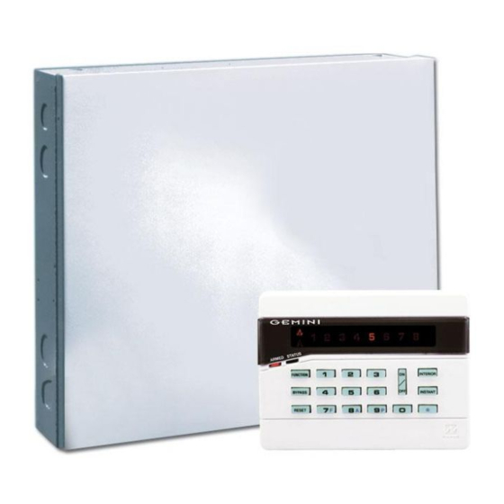
® GEM-P800 Control Panel/Communicator Installation Instructions © NAPCO 1997 WI850A 8/97 Wi850a Tuesday, September 16, 1997 08:01 page 1... - Page 2 User 8 code as an Ambush code. Wireless Ready Ordering Information ........4 Optional Accessories........4 Bell Supervision The GEM-P800 is wireless ready. When used with a Programming the Panel........5 GEM-RECV-XP8 receiver, the control panel can sup- Line Cut Detection Installation............6 port up to 8 wireless zones, 4 wireless smoke detec- Answering Machine Override (Second Call) Wiring...............6...
- Page 3 Housing Dimensions : -------------- 11" x 12 " x 3" (28 x 30.8 x 7.6) HxWxD Maximum Charging Current: -------165 mA Shipping Weight: -------------------- GEM-P800 5.5 lbs. Maximum Input Current: -------------2.58 A Operating Temperature: ------------ 0-49ºC (32-120°F) Wi850a Tuesday, September 16, 1997 08:01...
- Page 4 WI850A GEM-P800 Installation Instructions GEM-P800 Compatible Smoke Detectors GEM-P800 8 zone Control Panel with 2-wire fire 4-Wire 2-Wire Smoke Detector GEM-RP8 Keypad Smoke Detector Smoke Detector Base Zone Doubling Resistors (2.2K & 3.9K) OI219 Operating Instructions GEM-P800 WI851 Programming Instructions GEM-P800...
- Page 5 3. Connect terminal 15 (PGM) to terminal 3. attempting to report. +PWR GREEN RING RING 4. Apply power to the GEM-P800 control panel. TELCO PHONE 5. After a few seconds the ARMED, READY and SYSTEM TROUBLE LEDs will flash. GREEN 6.
- Page 6 WI850A GEM-P800 Installation Instructions ,QVWDOODWLRQ :LULQJ For increased protection, additional detectors should be installed in areas other than those required, such as the dining room, bedrooms Mounting the Panel Grounding the Panel and utility room. Heat detectors, rather than Mount the Panel close to an unswitched AC...
- Page 7 Keypad Sounder Wire the Fire Zone as shown in the Wiring Diagram in the back of this manual. An EOL NAPCO’s EZ Zone Doubling is simple. Each QUICK BEEPS terminal has 2 zones, use an E (2.2 K) type Zone...
- Page 8 WI850A GEM-P800 Installation Instructions Keyfob have been programmed for Full Set Keypad LEDs [81-84]. To arm the system with all zones pro- tected press the key. Press and hold the ARMED LED DEFINITION Arming (System ON) Armed key for 1.5s to fully set the system...
- Page 9 Tone. Enter a valid Arm/Disarm code, then Home Bypassing a zone press . If a valid Arm/Disarm code is entered, Press the key, then the zone number to be Exit/Entry Zone is not violated Zones selected as Home/Away with Delay the keypad will beep 6 times, indicating the panel bypassed.
- Page 10 WI850A GEM-P800 Installation Instructions While in User Program Mode the Armed, Status matically every *24 hours to ensure proper bat- of 1234, program the 4-digit User 1 Code through Dealer Programming [95]. User 1 Arm/Disarm System Trouble LEDs will continue to tery operation under load.
- Page 11 Keypad will chime on any zone that has not been SIGNAL STRENGTH KEYPAD SOUNDER line and the Control Panel phone line. When selected as an Exit/Entry Follower Zone , Home/ ready, tell the installer to arm, then disarm. 3 or less S BEEP Away with Delay Zones, or 24 Hour Zone .
- Page 12 WI850A GEM-P800 Installation Instructions from a Keyfob. Program the Keyfob AUX Remote Activation Using NAPCO’s Quickloader Software 1 or AUX 2 button for Full Set [81-7]. (Version 3.26 or higher), follow the instruc- [00]Exit/Entry Zones tions below: is Entered during Exit Time , Home/Away with...
- Page 13 cally be unbypassed and any subsequent [07]Burg (Steady) Output [11]Entry Delay violations of the zone will cause an alarm Enables the Bell Output on a zone trip for Delay time permits entry through Exit/Entry condition. each zone selected. The Bell Output will Zone(s) after the system is armed without remain ON for the length of time pro- [04]24-Hour Protection...
- Page 14 WI850A GEM-P800 Installation Instructions Additional Programming required: [18]Test Timer Offset [15]Line Cut Time-to-Fail Select reporting to Telco 1 [36-3] or Telco 3 Enter the time, in hours, that a Test Timer Enable this feature by programming the de- [56-3]. will be reported after Dealer Mode has been lay time required to declare a line cut failure.
- Page 15 output for 5 seconds using the [22]Miscellaneous Features 1 [25]Programmable Output Features 3 (1) Abort Delay - Program to allow a 15 command. (1) AC Fail - Program to activate the PGM on second Delay (except 24 Hour Zones ) after (3) Follow Keypad Sounder - The follow- the loss of AC.
- Page 16 WI850A GEM-P800 Installation Instructions [33]Receiver Options [36]System Reporting, Telco 1 (1) 2300 Hz HS/Kissoff - Select 2300 Hz (1) Keypad Fire - Program to activate a Handshake and Kissoff. [30]Subscriber ID Number Keypad Fire report ( (2) Sumcheck - Only used for the following For 4/2 format enter a 4 digit number.
- Page 17 (2) Battery Restore - Program to activate a [42]Receiver Format (Telco 2) [46]Communicator Features 2 Battery Restore report. Select the format that will be used to report (1) No Dial Tone Detection - Program to (3) Trouble Restore - Program to activate a for Telco 2 (Backup reporting).
- Page 18 WI850A GEM-P800 Installation Instructions Pager Alarm data is the same as 4/2 format [49]Pager Options 3/1 format - Sends only the report Code and with the exception that the 2 digit Report (1) Skip Alarm Data - Once pager format is does not append it with the zone number.
- Page 19 Fire, Keypad AUX, Keypad Panic, Test Up to two receivers can be wired to the [67]Telephone Number 1 Timer, AC Fail, Low Battery, Trouble and GEM-P800. Each wireless transmitter can (1) Opening After Alarm (Cancel Code) - Fire. be mapped to a zone.
- Page 20 WI850A GEM-P800 Installation Instructions Find Mode) or saved to the LOG (see Signal Enter the RF ID# and AUX 1 and AUX 2 buttons on the Keyfob are pressed. Strength Logging Mode - pg. 11). options for each Keyfob. Press the button to turn the Bell OFF.
- Page 21 Smoke Supervisory Timer, a system the downloading computer, call the panel. trouble ‘RF Smoke Supervisory Failure' will 1. Create the GEM-P800 account to be When the operator has determined that the be indicated on the keypad. downloaded using PCD3000 Quick- panel has received 1-2 rings, pressing the loader Software.
- Page 22 WI850A GEM-P800 Installation Instructions played on the Fire LED. Fire Trouble is 5. Enter Standby Mode by entering [95]User 1 Code indicated by a steady Fire LED. The 1st User code is a program code as The Computer is now in STANDBY well as an Arm/Disarm code.
- Page 23 EXAMPLE Audible System Trouble Indication - For all LOW BATTERY SYSTEM TROUBLE DISPLAY system troubles, except when the only system Enter to enter System Trouble mode Use the System Trouble chart on the following trouble is the loss of AC, the keypad will beep and determine the specific trouble.
- Page 24 WI850A GEM-P800 Installation Instructions Keypad Beeps or Zone LED System Trouble Cause/Action Condition SYSTEM Flashes 1 Beep This trouble will occur if AC power is not present. Ensure that the transformer is connected to an unswitched power source. AC Power Failure If there has been a recent power failure, the battery may be partially depleted and must be recharged by the control panel.
- Page 25 Zones programmed as Exit/Entry 6. The PGM Output Pulses in Alarm. Followers When the PGM lug of the control panel is 2. Zones programmed for 24 Hour Pro- programmed for an Armed indication it also 1. The bell output drops to about 3 volts in tection.
- Page 26 WI850A GEM-P800 Installation Instructions 12. No Keypad Chime? 8. How do I remove Keypad Sounder on If using internal reed, make sure J1 is The keypad sounder is turned off with the Alarm? cut and both Point 1 and Point 2 termi- nals are jumped out.
- Page 27 GEM-P800 WIRING DIAGRAM This equipment should be installed in accordance with Chapter 2 (REFER TO INSTALLATION INSTRUCTIONS WI850) of the National Fire Alarm Code, ANSI/NFPA 72-1993 (National Fire Protection Association Batterymarch Park, Quincy MA RESIDENTIAL BURG (4 HOUR STANDBY) 02269). and local codes. Information describing proper installa- COMBINED STANDBY = 500 mA BELL = 2.0 AMP...
- Page 28 NAPCO neither assumes, nor authorizes any other person purporting to act on its behalf to modify, to change, or to assume for it, any other warranty or liability concerning its products. In no event shall NAPCO be liable for an amount in excess of NAPCO's original selling price of the product, for any loss or damage, whether direct, indirect, incidental, consequential, or otherwise arising out of any failure of the product.