
Summary of Contents for Fluke Network Tester
-
Page 1: Users Manual
™ NetTool Inline Network Tester Users Manual PN 1560821 June 2000, Rev 3, 3/05 © 2000-2005 Fluke Corporation, All rights reserved. All product names are trademarks of their respective companies. - Page 2 Fluke Networks authorized resellers shall extend this warranty on new and unused products to end-user customers only but have no author- ity to extend a greater or different warranty on behalf of Fluke Networks. Warranty support is available only if product is purchased through a Fluke Networks authorized sales outlet or Buyer has paid the applicable international price.
-
Page 3: Table Of Contents
Care and Maintenance ... 1-2 Package Contents ... 1-2 Optional Accessories... 1-3 Service and Adjustment... 1-3 Registering NetTool... 1-3 Contacting Fluke Networks... 1-4 PC/NetTool Link Utility Programs ... 1-4 NetTool Blaster... 1-4 NetTool Toolkit ... 1-5 Installing and Running the Link Utilities ... 1-5 Getting Acquainted... - Page 4 Users Manual Understanding the LEDs ... 1-6 NetTool Menus... 1-7 Power Supply... 1-9 Installing the Batteries... 1-9 Maximizing Battery Life ... 1-9 Using the AC Adapter ... 1-9 Updating NetTool’s Software ... 1-10 Setting Up and Connecting NetTool... 2-1 Introduction ... 2-1 Configuring NetTool ...
- Page 5 AutoTest... 3-1 Introduction ... 3-1 Running AutoTest... 3-1 Cable Test Results ... 3-2 Cable Length, Opens, Shorts, and Splits ... 3-2 Wiremap ... 3-2 Single-Ended AutoTest Results... 3-3 Network Drop... 3-3 Network Device... 3-4 Inline AutoTest Results... 3-5 Inline between a Device and the Network... 3-5 Inline between a PoE Powered Device and the Network...
- Page 6 Users Manual Ping... 5-4 Assigning an IP Address to NetTool... 5-4 Pinging a Single Device ... 5-4 Pinging Multiple Devices ... 5-5 Common Problems ... 6-1 Introduction ... 6-1 Displaying the Problem Log ... 6-1 Understanding the Problem Log Display... 6-2 Things to Consider ...
- Page 7 Viewing VLAN and CDP Information ... 7-2 The VoIP Log ... 7-3 Viewing Call Quality Measurements... 7-4 Creating and Managing Reports ... 8-1 Introduction ... 8-1 Before You Begin ... 8-1 Creating a Report ... 8-2 Deleting or Overwriting a Report ... 8-3 Appendices Specifications ...
- Page 8 NetTool Users Manual...
-
Page 9: List Of Tables
List of Tables Table Title Page 1-1. NetTool's Device Icons ... 1-7 3-1. Services NetTool Discovers ... 3-4 3-2. Duplex Settings ... 3-5 3-3. Link and Polarity Level ... 3-6 5-1. Ping Status Icons ... 5-6 6-1. Elements of the Problem Log ... 6-2 7-1. - Page 10 NetTool Users Manual viii...
-
Page 11: List Of Figures
List of Figures Figure Title Page 1-1. NetTool Front Panel ... 1-1 1-2. Initial Screen... 1-5 1-3. NetTool LEDs ... 1-6 1-4. NetTool Icons ... 1-7 1-5. Battery Compartment ... 1-9 1-6. Powering NetTool with the AC Adapter ... 1-9 2-1. - Page 12 NetTool Users Manual 3-5. Diagram of an Inline Connection... 3-5 3-6. Inline Connection Between a PoE-Powered Device and the Network ... 3-7 4-1. Station Menu... 4-1 4-2. Link Configuration Details ... 4-2 4-3. Health Details... 4-3 4-4. Health Statistics ... 4-3 4-5.
-
Page 13: Introduction
Using This Manual This Users Manual is supplied with the NetTool™ Inline Network Tester (hereafter referred to as NetTool) to help you learn to use your new tester quickly and more efficiently. The manual introduces you to the key features... -
Page 14: Nettool Features
NetTool Users Manual NetTool is available in the following models: • NetTool Standard: provides single-ended testing of network devices. Also includes a Ping function and the capability to display VLAN traffic and CDP information. • NetTool Pro: includes all of the features in the standard model plus the ability to do inline testing between two devices, such as a PC and the network switch. -
Page 15: Optional Accessories
(at Fluke Networks’ option) and returned to you, postage paid, at no charge. See the registration card for warranty terms. If the warranty has lapsed, Fluke Networks will repair the tester for a fixed fee and return it, postage paid, to you. Registering NetTool Please take the time to register your NetTool. -
Page 16: Contacting Fluke Networks
NetTool Users Manual Contacting Fluke Networks www.flukenetworks.com support@flukenetworks.com +1-425-446-4519 • Australia: 61 (2) 8850-3333 or 61 (3) 9329 0244 • Beijing: 86 (10) 6512-3435 • Brazil: 11 3044 1277 • Canada: 1-800-363-5853 • Europe: +44 1923 281 300 • Hong Kong: 852 2721-3228 •... -
Page 17: Nettool Toolkit
A navigation screen displays. Run the setup program to install both programs. Run the link utility programs from the Start | Programs | Fluke Networks...menu. Getting Acquainted Getting Acquainted This section shows you how to turn NetTool on and off and acquaints you with the functions of the tester’s... -
Page 18: Understanding The Leds
NetTool Users Manual Understanding the LEDs On each side of the LCD, NetTool has a pair of LED indicators (Figure 1-3). These LEDs combine to give you immediate insight and at-a-glance information about your network environment. The top pair of LEDs provides link, collision, and error information while the bottom pair indicates utilization levels. -
Page 19: Nettool Menus
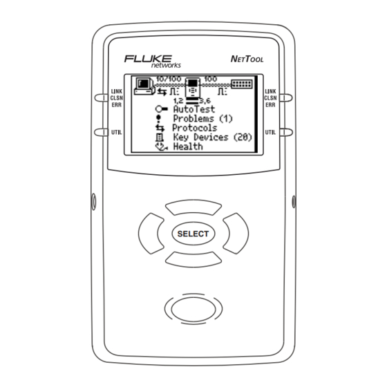
NetTool Menus NetTool has an icon- and menu-driven user interface. Icons The top area (Figure 1-4) contains a connection diagram. This diagram contains icons that show what type of device is connected to NetTool’s RJ-45 jacks. Figure 1-4. NetTool Icons NetTool’s device icons are listed in Table 1-1. -
Page 20: Navigation Keys
NetTool Users Manual • Key Devices: displays all of the servers, routers, and printers that NetTool finds on the network. • Toolkit or VoIP/Toolkit (so named if the VoIP option is installed): displays the Toolkit menu where you can access the Ping utility, the Reporter function, and health statistics. -
Page 21: Power Supply
Power Supply To supply power to the tester, you can use the four AA size batteries (supplied) or the (optional) rechargeable batteries. Alternatively, you can use the (optional) AC adapter. Installing the Batteries Figure 1-5 shows you how to insert the four AA batteries into the tester’s battery compartment. -
Page 22: Updating Nettool's Software
NetTool Users Manual Updating NetTool’s Software From time to time, updates to NetTool’s software become available. • Select the NetTool icon then select About NetTool to find out what version of software is installed on the tester. • To find out if there is a new software version available, go to www.flukenetworks.com. -
Page 23: Setting Up And Connecting Nettool
Introduction This chapter shows you how to set up NetTool. Among the tasks covered are how to set NetTool’s date and time, how to configure its IP address information, and how to locate important information, such as the serial number. This chapter also shows you how to make a single-ended connection and an inline connection between NetTool and a network device. -
Page 24: Changing The System Settings
NetTool Users Manual Changing the System Settings Select Settings to display the Settings menu: Figure 2-2. Settings Menu On this menu, you can do the following: • Check the battery level. If NetTool is running on battery power, the battery level indicator is displayed at the top of every Setup screen. -
Page 25: Identifying Unwanted Protocols
• Restore factory default settings. Restore Defaults Select to restore all of NetTool’s factory default settings. Identifying Unwanted Protocols Select Unwanted Protocols to display a screen that allows you to identify protocols on the network that you want NetTool to warn you about. This feature can be especially helpful to you during a network-wide migration away from certain protocols. -
Page 26: Creating A List Of Ip Addresses To Ping
NetTool Users Manual Press SELECT to save the IP address for NetTool. NetTool lists the updated address with the subnet and router IP addresses. In like manner, configure the subnet mask and router addresses. NetTool assists you by entering the first parts of those addresses based on common addressing rules. -
Page 27: Connecting Nettool
Connecting NetTool NetTool has two RJ-45 jacks, one on each side. Use the supplied RJ-45 cable to connect a patch cable to NetTool and to create a single-ended or inline connection. NetTool also has a serial port, which enables you to directly connect the tester to a PC. - Page 28 NetTool Users Manual Figure 2-4 shows a single-ended connection to a wall jack. Figure 2-4. Single-Ended Connection into a Wall Jack. Use this type of connection when you need to check a network drop for activity and to find out what services lie on the other side.
-
Page 29: Inline Connection
Inline Connection An inline connection entails having NetTool simultaneously plugged in between two network devices, such between as a PC or a PoE-powered device and a network switch. Use this type of connection to verify whether the device can communicate properly with the network. -
Page 30: Serial Port Connection
NetTool Users Manual Serial Port Connection Note The recommended speed setting for the serial port is 115200. A serial port connection enables you to: • Download software (see “Updating the Software”) • Enable options • Save screens • Upload and download PING catalogs •... -
Page 31: Autotest
Introduction AutoTest provides a good starting point for trying to determine what devices are on your network and for making a quick assessment of your network’s overall condition. Results from AutoTest can alert you to connectivity problems before they impact network performance. -
Page 32: Cable Test Results
NetTool Users Manual Cable Test Results If NetTool is connected to a patch cable, AutoTest evaluates the integrity of the cable and finds errors that might suggest a physical media problem. If a wiremap adapter is attached, NetTool performs deeper testing of the cable by additionally verifying pin-to-pin connectivity. -
Page 33: Single-Ended Autotest Results
Single-Ended AutoTest Results AutoTest result screens vary depending on the device that NetTool is connected to. Note This results described in this section are provided as examples of what information NetTool provides. Network Drop If NetTool is connected to a network drop, it displays one of the following icons to identify the service that is active on the jack: •... -
Page 34: Network Device
NetTool Users Manual Table 3-1 lists the devices and services that NetTool discovers. Table 3-1. Services NetTool Discovers Device Services Servers IP Servers (IP services discovered): DHCP, DNS, email (SMTP, POP, IMAP), Web (HTTP, HTTP proxy), WINS. NetWare Servers (IPX service types): Nearest File Server, File Server, NetWare Access server, Time Synchronization Server, NetWare Directory Server (NDS),... -
Page 35: Inline Autotest Results
Inline AutoTest Results The diagrams at the top of the screen can give you a quick indication of what is going on with your network. Inline between a Device and the Network Caution When operating inline with a POE-powered device connected to NetTool, make sure that NetTool is not plugged into the AC adapter or into a serial device that is grounded or damage may occur to the equipment. - Page 36 NetTool Users Manual Polarity information is also given. The waveform-shaped icons used in the diagram are listed in Table 3-3. Table 3-3. Link and Polarity Level Indicator Definition Normal level, normal polarity Normal level, reverse polarity Low level, normal polarity Low level, reverse polarity.
-
Page 37: Inline Between A Poe Powered Device And The Network
To get detailed results, move the cursor to one of the following icons then press SELECT: • PC icon : enables you to view results for the device. Go to Chapter 4 “Troubleshooting a Network Device” for details. • Network icon : enables you to view network results. - Page 38 NetTool Users Manual...
-
Page 39: Troubleshooting A Network Device
Introduction NetTool can provide information that you can use to determine whether a device is configured properly for your network. After you have confidence that all of the stations and devices on your network are configured correctly, you can move on to evaluate the entire network. This chapter shows you how to resolve device and configuration problems. -
Page 40: Viewing Link Status Information
NetTool Users Manual Five basic types of information about the device or network can be selected from this menu: • Link Config: provides link pulse information. If the VoIP option is installed, you can also find out PoE voltage and pair information. •... -
Page 41: Checking Frames For Errors
Checking Frames for Errors To find out how many frames have been transmitted and whether any errors were discovered in those frames, display the Health screen (Figure 4-3): Figure 4-3. Health Details This screen enables you to look at the status of frames transmitted across the link since AutoTest began. - Page 42 NetTool Users Manual To change what NetTool is viewing in real-time and to change the direction (that is, “to/from Network” or “to/from PC”), move the cursor to the desired device icon (located in the upper right or left). Then press SELECT.
-
Page 43: Tracking Protocols
Tracking Protocols Note You can also view protocol information by selecting Protocols from the Main menu. To find out what protocols are associated with a device or running on the network, do the following: Display the Protocols screen (Figure 4-5): Figure 4-5. -
Page 44: Obtaining A Device's Ip Address Information
NetTool Users Manual Obtaining a Device’s IP Address Information To obtain IP address information for a device, do the following: Select Addresses Used to display the following: Figure 4-7. Addresses Used Screen The Addresses Used screen enables you to verify a devices’... -
Page 45: Identifying Network Resources
You can also find out what VLAN a device belongs to. Press the Down arrow key to locate VLAN statistics, as shown in Figure 4-9: Figure 4-9. VLAN Information NetTool can provide information for up to five discovered VLANS. This screen shows the VLAN’s ID, its priority, frame counts, and the untagged frame count. - Page 46 NetTool Users Manual...
-
Page 47: Troubleshooting Networks
Introduction The information documented in this chapter can help you evaluate the health of your network and assist you with troubleshooting network problems. NetTool features a Ping test, which is described in this chapter. Use this test to verify connectivity between devices on the network. -
Page 48: Identifying The Network Type
NetTool Users Manual Four basic functional groups of information about the network are listed on this menu: • Link Config: provides link pulse information about the network. See “Viewing Link Status Information” in Chapter 4 for details. • Health: lets you monitor frames and view errors that indicate problems on the link. -
Page 49: Identifying Key Devices
This screen also tells you which VLAN NetTool is connected to. If CDP information is found, it is also reported on this screen. Note The Segment ID screen is identical to the Addresses Used screen documented in Chapter 4. For information on VLANs and CDP, see “Obtaining a Device’s IP Address Information”... -
Page 50: Ping
NetTool Users Manual Ping NetTool can automatically ping any single device on your network or a group consisting of up to 10 devices. Ping provides instant information about how a network device is connected and how it is acting on your local segment, making it easier for you to pinpoint connectivity problems. -
Page 51: Pinging Multiple Devices
Do one of the following: • Select the IP address of the device from the list. • Select Add New Device to display the Edit screen. On this screen, supply the IP address of the device then select Update. NetTool pings the device and automatically adds its address to a running list (up to 10) of recently pinged devices. - Page 52 NetTool Users Manual To view results for a particular IP address, move the cursor to the address, then press SELECT. The Ping Results screen (Figure 5-6) for your selection is displayed: Figure 5-6. Ping Results Screen To ping the list of IP addresses again, move the cursor to the name of the catalog, then select Restart.
-
Page 53: Common Problems
Introduction The Problem Log includes a listing of all problems that NetTool detected from the physical layer to application layer. Not every problem contained in this log is at the same level of severity; therefore, just because a problem is listed here does not imply that it is a catastrophic one. For example, Unwanted Protocols are included in this log, but they are not a major impediment to the operation of a PC on the network. -
Page 54: Understanding The Problem Log Display
NetTool Users Manual The Problem Log (Figure 6-2) is displayed: Figure 6-2. Problem Log Understanding the Problem Log Display There are nine types of problems listed in the Problem Log. Each type of problem has an icon associated with it. For example, a stethoscope is used to identify health- related problems. -
Page 55: Things To Consider
Things to Consider You can think of problems fitting into one of two categories: link connectivity or network. Link connectivity problems relate to cabling or cabling properties while network problems involve PC/network configuration settings or PC-to-server interactions. Generally, you encounter network problems while setting up or changing a PC’s connection to the network. - Page 56 NetTool Users Manual • Problem: Pair mismatch Explanation: The link pulse is being sourced on the same wire pair by both sides. This problem does not prevent connection to the network. NetTool automatically swaps the pairs to correct this problem. Remedy: Check the cabling.
-
Page 57: Network Problems
Network Problems This section lists all of the network problems. Keep in mind that this is not an exhaustive list of troubleshooting steps. If you know what you need, the network administrator for the network you are troubleshooting can provide you with a lot of information to correct these problems. -
Page 58: Netware
NetTool Users Manual NetWare • Problem: Ethernet frame-type mismatches. Explanation: For the PC and network to communicate, they both must be configured for the same frame type (802.3-raw, 802.2, Ethernet II, and SNAP). You can configure a client for a single frame type. -
Page 59: Tcp/Ip
TCP/IP • Problem: PC using incorrect IP subnet mask. Explanation: NetTool has determined that the PC is not properly configured. Remedy: Access PC network properties and correct the IP subnet mask. • Problem: Router issued ICMP redirect. Hosts or devices using incorrect gateway/routers. Explanation: NetTool has determined that the PC is not properly configured. -
Page 60: Name Resolution
NetTool Users Manual • Problem: DHCP server issuing IP address that causes duplicate IP on network. Explanation: The DHCP server in question is not detecting an address and is provisioning a duplicate. Remedy: This problem can be caused by a statically configured PC. -
Page 61: Netbios
• Problem: No WINS server found on network to resolve names. Explanation: The PC is configured to use WINS (Windows Internet Name Service) and none can be found. Remedy: Make sure the WINS server is up and running. Access the PC’s network properties. •... -
Page 62: Web
NetTool Users Manual • Problem: xxx.xxx.xxx.xxx causing duplicate NetBIOS name. Explanation: Only one unique NetBIOS name is allowed on a domain. Remedy: The name specified on the PC needs to be changed to eliminate duplication. • Problem: PC involved in MB elections. Explanation: NetTool sees packets from the PC that are generating master browser elections on the network. -
Page 63: Printer
• Problem: Unable to connect to POP3 server Explanation: The PC cannot find the POP3 server it is configured to find. The server itself may be down as well. Remedy: Access NetTool’s Key Devices list to view information about this server and then make corrections within the mail setup area of the PC. -
Page 64: Unwanted Protocols (When Enabled)
NetTool Users Manual Unwanted protocols (when enabled) The purpose of the Unwanted Protocols feature is to enable you to find protocols that you do not want on the network. For example, if you have migrated away from NetWare on the network, NetTool will flag a device that still has NetWare configured on it. -
Page 65: Verifying Voice Over Ip Service
Introduction With the VoIP (Voice over IP) option enabled, you can use NetTool to verify VoIP service on a link. NetTool can track SCCP/SIP call control and measure RTP quality of service. The VoIP Log and VoIP Monitor capture call transactions, providing you with a step-by-step record of major events so that you can troubleshoot problems with VoIP service. -
Page 66: Viewing Poe Voltage And Pair Information
NetTool Users Manual Viewing PoE Voltage and Pair Information After you run AutoTest, you can obtain PoE voltage and pair information for the network or phone side. Do the following: Depending on which side you want to look at, select one of the following icons: •... -
Page 67: The Voip Log
When plugged into a switch VLAN port, the native and appliance (phone) VLANs are also displayed along with the CDP information, as shown in Figure 7-2: Figure 7-2. VLAN Port Information The VoIP Log The VoIP Log is a per-call event log that records major SCCP/SIP and RTP events and measurements. -
Page 68: Viewing Call Quality Measurements
NetTool Users Manual Viewing Call Quality Measurements The VoIP Monitor tracks call quality (RTP data). To display the VoIP Monitor, do the following: From the Main menu, select VoIP/Toolkit. On the VoIP/Toolkit menu, select VoIP Monitor to display the screen shown in Figure 7-4: Figure 7-4. -
Page 69: Creating And Managing Reports
Introduction NetTool’s Reporter feature enables you to capture device and network configuration data and save that information in a report. You can create and save up to 10 reports. Reporter helps you do the following: • Document configurations for groups of users (for example, Customer Service, Marketing, and Technical Support) •... -
Page 70: Creating A Report
NetTool Users Manual Creating a Report Reporter enables you to create a report that reflects what NetTool currently detects on the PC (or another device) and/or the network. To create a report: Connect NetTool to the device you want to check and run AutoTest. -
Page 71: Deleting Or Overwriting A Report
Move the cursor to Save Report. Then, press SELECT to save. If you inadvertently give two reports the same name on NetTool, check the date/time stamp when you view the reports to differentiate between them. After you save a report, you can use NetTool Toolkit to upload, view, and print it. - Page 72 NetTool Users Manual...
-
Page 73: Appendices
Appendices Appendix Title Page Specifications ... A-1 VoIP Logs ... B-1 Glossary ... C-1... -
Page 75: Specifications
General Specifications Media Access 10Base-T and 100Base-TX. Cable Tests Internal wiremap, cable length, opens, shorts, and split pairs Ports Shielded Hub/NIC connector (RJ-45). Serial port – customized 2.5mm “stereo” input jack. Interface Push button navigation of icon/menu-driven view. Battery Removable alkaline batteries or optional rechargeable NiMH batteries. Dimensions 12.5 cm x 7.8 cm x 4.3 cm Weight... -
Page 76: Environmental Requirements
The optional Universal AC Adapter for NetTool has UL, CSA, and TÜV approvals or other approvals valid in the USA, Canada, and Europe. The Fluke NetTool complies with European standard EN 61326 Class B. Complies with European CE directive: EMC directive 89/336/EEC and low voltage directive 73/23/EEC. -
Page 77: Sample Voip Call Logs
Appendix B Sample VoIP Call Logs Introduction This appendix contains sample SCCP and SIP call logs. All of the logs contain running commentaries to familiarize you with the messaging and information that is exchanged during a call. - Page 78 NetTool Users Manual Typical Cisco Skinny (SCCP) Phone Bootup >DHCP DISCOVER 00c017a00079 >DHCP OFFER 129.196.197.016 >DHCP REQUEST 003094c4426f >DHCP ACK 129.196.197.016 >DNS req:003094c4426f CiscoCM1.danahertm.com <DNS response 129.196.197.244 >TFTP file request OS79XX.TXT >TFTP file request SEP003094C4426F.cnf.xml >ALARM TO CM 25: Name=SEP003094C4426F >REGISTER WITH CM ip:129.196.197.016 name:SEP003094C4426F...
- Page 79 Typical Cisco Skinny (SCCP) Phone Bootup (continued) <REGISTER_ACK >CAPABILITY_REQUEST <CAPABILITY_RESULT >TFTP file request SEP003094C4426F.cnf.xml >TFTP file request RINGLIST.XML >TFTP file request DISTINCTIVERINGLIST.XML >CDP SEP003094C4426F Cisco IP Phone 7960 // the Call Manager acknowledges the registration // the phone asks about its capabilities // the Call Manager replies // the hone TFTPs down three more files // the phone sends out CDP packets periodically...
- Page 80 NetTool Users Manual Typical Cisco Skinny (SCCP) Call Log Following is a sample SCCP call log. Events in the exchange are shown on the left. Commentary appears on the right to help you follow the sequencing of the exchange. The log captures an entire phone transaction, starting with the phone going OFF HOOK: CallMgr:129.196.197.244 OFF HOOK...
- Page 81 Typical Cisco Skinny (SCCP) Call Log (continued) RTP streaming… 129.196.197.023:30142 VLAN:untag TOS:0xb8 129.196.197.016:20828 VLAN:untag TOS:0xb8 Call Duration:9.51s ON HOOK >RTP cnt:475frms Jitter:994us Arrival Avg:19ms Min:19ms Max:20ms Drop:3fr DropBurst:61ms // the conversation has started // phone 1 IP address and port number // phone 1 VLAN and TOS being used // phone 2 IP address and port number // phone 2 VLAN and TOS being used...
- Page 82 NetTool Users Manual Typical Cisco Skinny (SCCP) Call Log (continued) // phone 2 stats <RTP cnt:476fr Jitter:1ms Arrival Avg:20ms Min:19ms Max:20ms Drop:0fr DropBurst:0s Call Complete...
- Page 83 Typical SIP Phone Bootup Log >DHCP DISCOVER 000f66fc9e72 >DHCP OFFER 129.196.196.202 >DHCP REQUEST 000f66fc9e72 >DHCP ACK 129.196.196.202 >DNS req:000f66fc9e72 atlas4.atlas.vonage.net <DNS response 216.115.025.056 REGISTER sip:atlas4.atla 200 OK >DNS req:000f66fc9e72 time.vonage.net <DNS response 216.115.031.140 REGISTER sip:atlas4.atla 200 OK // the phone broadcasts an IP address request // the MAC address of the phone // the DHCP server offers an address // the offered IP address...
- Page 84 NetTool Users Manual Typical SIP Phone Bootup Log (continued) >DNS req:000f66fc9e72 ls.tftp.vonage.net <DNS response 192.015.192.015 >TFTP file request /uObE8NkRvq/spa000F66FC9 REGISTER sip:atlas4.atla 200 OK REGISTER sip:atlas4.atla 200 OK // the phone looks up the FTP file server // the DNS server responds with the IP address // the phone downloads its operating file // the phone sends periodic heartbeat registration // the gateway responds...
- Page 85 Typical SIP Call Log INVITE sip:5983842@atlas 407 Proxy Authentication ACK sip:5983842@atlas4.a INVITE sip:5983842@atlas 100 Trying 180 Ringing 180 Ringing 200 OK SIP RTP port 12436 ACK sip:17195983842@216. Call Setup:213ms RTP streaming... 129.196.196.202:10106 VLAN:untag TOS:0xb8 216.115.023.031:12436 VLAN:untag TOS:0x0 BYE sip:17195983842@216. // the phone invites the other party // the gateway acknowledges the number // the gateway tries connecting // the far end is ringing...
- Page 86 NetTool Users Manual Typical SIP Call Log (continued) >RTP cnt:2186fr Jitter:21ms Arrival Avg:19ms Min:7ms Max:29ms Drop:23fr DropBurst:21ms <RTP cnt:2233fr Jitter:162ms Arrival Avg:19ms Min:830us Max:163ms Drop:0fr DropBurst:0s Call Complete B-10 // phone 1 stats—the number of RTP frames // the inter-frame arrival jitter // the average arrival of the frames // the minimum and maximum inter-arrival time // the number of dropped frames...
-
Page 87: Glossary
10BASE2 Sometimes called ThinLAN or CheaperNet, 10BASE2 is the implementation of the IEEE 802.3 Ethernet standard on thin coaxial cable. The maximum segment length is 185 meters. Appendix C 10BASE5 Sometimes called ThickLAN, 10BASE5 is the implementation of the IEEE 802.3 Ethernet standard on thick coaxial cable. - Page 88 NetTool Users Manual 10BASEF A point-to-point fiber link. This is the draft specification for IEEE 802.3 Ethernet over fiber optic cable. 10BASE-T 10BASE-T is the implementation of the IEEE 802.3 Ethernet standard on unshielded twisted-pair wiring. It is a star topology, with stations directly connected to a multi- port Hub, and it has a maximum cable length of 100 meters.
- Page 89 ARP (Address Resolution Protocol) A member of the TCP/IP protocol suite, ARP is the method by which a station’s MAC address is determined given a station’s IP (Internet Protocol) address. Attenuation A reduction in the strength of a signal; the opposite of gain.
- Page 90 NetTool Users Manual Client A client is a computer that makes requests of a server. A client has only one user; a server is shared by many users. Collision A collision is the result of two or more nodes transmitting at the same time.
- Page 91 The address of the station receiving a frame. Domain Name Services provides a mechanism that allows users to remember logical machine names rather than IP addresses. DNS provides mapping between a machine name (e.g., www.fluke.com) and its IP address (e.g., xxx.xxx.xxx.xxx). EIA568 Electronic Industries Association Commercial Building Telecommunications Wiring Standard.
- Page 92 NetTool Users Manual Full-Duplex 10Base-T and 100Base-TX network operation using a switching Hub to establish a point-to-point connection between LAN nodes that allows simultaneous sending and receiving of data packets. Full-duplex performance is twice that of half-duplex performance. A 10Base-T full- duplex network is capable of 20 Mb/s data throughput, while a full-duplex 100Base-TX network is capable of 200 Mb/s throughput.
- Page 93 Jabber A frame greater than the maximum legal size (greater than 1518 bytes) with a good or bad frame check sequence. In general, you should not see jabbers. The most likely causes of jabbers are a faulty NIC/driver or perhaps a cabling problem. Jitter Variability in latency, or delay.
- Page 94 NetTool Users Manual NEXT Near-end crosstalk; crosstalk between two twisted pairs measured at the same end of the cable as the disturbing signal source. NIC (Network Interface Card) A network interface card is the adapter card that plugs into a computer to provide a network connection. Node Number Node number identifies the device of interest.
- Page 95 Remote Collision A collision that occurs on the other side of a repeater. Since a 10BASE-T Hub is a multi-port repeater with a "segment" dedicated to each station, 10BASE-T collisions are remote collisions. Repeater A repeater is a layer-1 device that regenerates and retimes frames.
- Page 96 NetTool Users Manual RTCP (Real-time Transport Control Protocol) A protocol that provides insight on the performance and behavior of the RTP media stream. Runts Typically defined as an Ethernet frame which is less than 64 bytes. Depending on what device is counting the runts, the frame check sequence may be good or bad.
- Page 97 SNAP (Subnetwork Access Protocol) An IP protocol that is an extended version of the IEEE LAN logical link control (LLC) frame. SNAP provides access to additional protocols and allows vendors to create their own protocol sub-types. SNMP (Simple Network Management Protocol) Designed by the Department of Defense and commercial TCP/IP implementors, SNMP is part of the TCP/IP protocol suite.
- Page 98 NetTool Users Manual Topology Topology is the organization of network components. The topology of Token Ring network components is a ring. Transport Transport refers to the physical method by which data is transmitted (e.g., Ethernet, Token Ring, etc.). Different physical network hardware and cable layout are required for different transports.
-
Page 99: Index
A-2 equipment (supplied), 1-2 errors, viewing, 4-3 Index —F— factory default settings, restoring, 2-3 feet/meters, changing, 2-2 Fluke Networks, contacting, 1-4 —H— Health screen, 4-3 —I— inline connection, 2-7 IP address, setting NetTool's, 2-3 —K— Key Devices screen, 5-3... - Page 100 Users Manual —L— LEDs Link, Collision, and Error, 1-6 Utilization, 1-6 Left/Right arrow keys, 1-8 link and polarity levels, 3-6 Link Config screen, 4-2 —M— measurement units, changing, 2-2 menus closing current screen, 1-8 icons, 1-7 Main, 1-7 navigating, 1-8 paging up/down, 1-8 scrolling, 1-8 meters/feet, changing, 2-2...
- Page 101 2-8 servers discovered, 3-4 Servers Used screen, 4-7 single-ended connection, 2-5 specifications, A-1 Station menu, 4-1 —T— telephone numbers (Fluke Networks), —U— Unwanted Protocols screen, 2-3 Up/Down arrow keys, 1-8 —V— VLAN information, 7-2 VoIP (Voice over IP)
- Page 102 NetTool Users Manual...