Fluke Ti20 User Manual
Thermal imager
Hide thumbs
Also See for Ti20:
- Application note (3 pages) ,
- Quick reference manual (2 pages) ,
- Quick start (2 pages)

Related Manuals for Fluke Ti20


Summary of Contents for Fluke Ti20
- Page 1 ® Ti20 Thermal Imager Users Manual January 2006 © 2006 Fluke Corporation, All rights reserved. All product names are trademarks of their respective companies.
- Page 2 Fluke authorized resellers shall extend this warranty on new and unused products to end-user customers only but have no authority to extend a greater or different warranty on behalf of Fluke. Warranty support is available only if product is purchased through a Fluke authorized sales outlet or Buyer has paid the applicable international price.
-
Page 3: Table Of Contents
Chapter Getting Started ... 1-1 Introduction... 1-1 Contacting Fluke... 1-1 Safety Information ... 1-2 Laser Warning Labels ... 1-3 Unpacking the Imager... 1-4 Features and Controls ... 1-6 Operating the Controls... 1-7 Focusing the Imager ... 1-7 Understanding the Trigger... 1-8 Using the AC Power Adapter ... - Page 4 Ti20 Users Manual Environmental Conditions ... 2-11 Ambient Temperature Derating and Thermal Shock ... 2-11 Emissivity ... 2-12 Reflected Temperature Compensation... 2-13 Advanced Imager Operation... 3-1 Data Management and Storage ... 3-1 Viewing Stored Images ... 3-1 Deleting Images... 3-2 Selecting a Palette ...
- Page 5 Table 1-1. Symbols... 1-2 1-1. Standard Accessories ... 1-5 1-3. Features and Controls... 1-7 2-1. Contents of the Home Display ... 2-3 C-1. Emissivity Values for Metals ... C-2 C-2. Emissivity Values for Non-Metals... C-4 List of Tables Title Page...
- Page 6 Ti20 Users Manual...
- Page 7 Figure 1-1. Laser Warning Labels ... 1-3 1-2. Standard Accessories ... 1-4 1-3. Ti20 Thermal Imager Features and Controls ... 1-6 1-4. Focusing the Imager ... 1-8 1-5. Using the AC Power Adapter... 1-9 1-6. Using the Battery Charger... 1-10 1-7.
- Page 8 Ti20 Users Manual...
-
Page 9: Getting Started
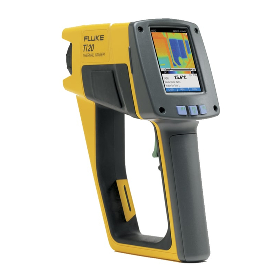
Introduction The Fluke Ti20 Imager (hereafter, “the Imager”) is a state-of-the-art, lightweight, pistol- grip style thermal imaging unit. Using the Imager, you can obtain instant and accurate thermal images and radiometric readings from distant targets. The Imager is ergonomically designed for right-hand or left-hand use, and captures thermal images and data with a simple trigger press. -
Page 10: Safety Information
Ti20 Users Manual Safety Information Use the Imager only as specified in this manual. See Table 1 for a list of symbols used on the Imager and in this manual. A W Warning identifies hazardous conditions and actions that could cause bodily harm or death. -
Page 11: Laser Warning Labels
Laser Warning Labels Euro/US < 1mW/630-670nm EN 60825/01 CAUTION Ti 20 THERMAL IMAGER Japanese CAUTION Ti 20 THERMAL IMAGER Figure 1-1. Laser Warning Labels Getting Started Laser Warning Labels Chinese CAUTION Ti20 THERMAL IMAGER dag133f.eps... -
Page 12: Unpacking The Imager
Ti20 Users Manual Unpacking the Imager Begin by opening the shipping box. Be sure to save the box and shipping materials in case you need to ship the Imager. Inside the shipping box, you will find a hard carrying case containing the standard accessories shown in Figure 1-2 and described in Table 1-2. -
Page 13: Standard Accessories
PN 2455818 Soft Case with Shoulder Strap PN 2446641 Rechargeable Battery Pack (2) PN 2492146 CD-ROM with InsideIR software and Users Manual and PN 2492154 Ti20 Training Material PN 2492228 Quick Reference Guide PN 2444076 International AC Adapter PN 2518704 Hard Case... -
Page 14: Features And Controls
Ti20 Users Manual Features and Controls Imager features and controls are shown in Figure 1-3 and described in Table 1-3. Figure 1-3. Ti20 Thermal Imager Features and Controls dag01f.eps... -
Page 15: Operating The Controls
Number Focus control Optical channel Laser aperture Wrist strap and attachment clip Trigger. The trigger is used to freeze a thermal image. Press the trigger one time to freeze the image for evaluation. You can save the image or press and release the trigger again to delete the image. -
Page 16: Understanding The Trigger
Ti20 Users Manual Optical Channel Understanding the Trigger The trigger is located in the standard trigger position for a pistol-grip device. The primary function of the trigger is to freeze a thermal image for possible storage to memory by the user. -
Page 17: Using The Ac Power Adapter
Getting Started Using the AC Power Adapter Using the AC Power Adapter dag007f.eps Figure 1-5. Using the AC Power Adapter... -
Page 18: Charging And Replacing The Batteries
Users Manual Charging and Replacing the Batteries With the Ti20, you have the option of using six AA batteries or a rechargeable NiMH pack. The use of both options is described in the following pages. Battery charger use is shown is Figure 1-6 and battery placement in Figure 1-7 . -
Page 19: Installing Or Replacing The Batteries
Installing or Replacing the Batteries Replace the batteries with six AA batteries (NEDA 15A or IEC LR6). Install or Replace the AA battery cartridge as described below and shown in Figure 1-7. 1. Unlock the battery compartment by using a standard screwdriver to turn the battery door screw one-quarter turn counterclockwise. -
Page 20: Attaching The Wrist Strap
Ti20 Users Manual Attaching the Wrist Strap A wrist strap is included with your Imager. You can attach the wrist strap by clipping the strap to the attachment clip on the Imager housing. 1-12 Figure 1-8. Attaching the Wrist Strap... -
Page 21: Inputs And Connections
Inputs and Connections Connecting the USB Cable The included USB cable can be used to either download or upload data from a PC to the Imager. To connect the USB cable, insert the smaller USB connector into the Imager port and the larger connector into the PC USB port as shown in Figure 1-9. -
Page 22: Mounting The Imager On A Tripod
Ti20 Users Manual Mounting the Imager on a Tripod A tripod mount is provided on the bottom side of the Imager. Rotate or screw the Imager onto a tripod using the tripod mount as shown in Figure 1-10. Ti 20... -
Page 23: Cleaning The Lens
Cleaning the Lens Although the lens is coated with a durable, erosion resistant coating (according to MIL standards), cleaning dust, sand, and other particles might scratch the coating and impair the performance of the lens. To avoid damage, do not use tools or sharp objects when cleaning the lens. - Page 24 Ti20 Users Manual 1-16...
-
Page 25: Basic Operation
After approximately 5 seconds, the Imager loads the Home display. The Imager splash screen is shown in Figure 2-1 and displays the following information: Date and Time Fluke and MicroIR logos Model Number Serial Number Firmware Version... -
Page 26: Understanding The Home Display
Ti20 Users Manual Understanding the Home Display The Imager returns to the Home display when you complete a menu operation, escape or cancel an operation using the G soft key, or the by pressing the trigger. Figure 2-2 illustrates the Home display zones. -
Page 27: Contents Of The Home Display
The contents of the Home display is described in Table 2-1. Table 2-1. Contents of the Home Display Displayed Number Zone Information Manual Calibrating Capture Review Delete or Delete Date and Time Header Thermal Image Description Auto Imager is in automatic imaging mode Imager is in manual imaging mode Indicates the Imager is calibrating and is temporarily incapable of measuring... -
Page 28: Aiming And Activating The Laser
Ti20 Users Manual Number Zone Information Aiming and Activating the Laser The laser is a sighting aid and is not required to take measurements. The laser is not coaxial with the infrared channel, and the laser dot is offset from the center of the thermal image (the crosshatch at the center of the display). -
Page 29: Capturing Images
The Japanese model of the Ti20 requires you to press and hold F to turn on the laser and keep it on. When you release F, the laser turns off. Capturing Images Recording images is a simple process but before starting you should note the current image location number. -
Page 30: Adjusting The Backlight
Ti20 Users Manual If no image is stored at the current memory location, the right side of the display is black. 3. Press G ( image location. Adjusting the Backlight Backlight ON is recommended for indoor use set the backlight OFF for outdoor applications and to save battery life. -
Page 31: Setting The Temperature Scale
Setting the Temperature Scale The Imager displays temperatures using either the Celsius or Fahrenheit temperature scales. The default temperature scale is Celsius. 1. Press G ( MENU scale function. 2. Press H (TEMPSCALE Celsius. Setting the Level In Manual mode, you can define Level and Span values manually. Manual mode allows you to bring both MIN and MAX values to the desired cut-off levels and to adjust the temperature interval to a minimum to maximizing color resolution. - Page 32 Ti20 Users Manual 3. Press F 4. Press F (4) to move the window to the left (lower) or H (5) to move the window to the right (higher). 5. Press G ) to access the set Level function. (LEVEL ) two times to return to the Home display.
-
Page 33: Adjusting The Span
Using Distance to Spot Size Ratio (D:S) The Ti20 imager views a portion of the scene that is 15 º high by 20 º wide (the Field-Of- View (FOV), of the Imager) as shown in Figure 2-3. This scene is displayed on the LCD on the back of the Imager. - Page 34 Ti20 Users Manual Measurement Spot (S = Diameter of the Spot) dag135f.eps Figure 2-3. Relationship Between FOV and Measurement Spot and Reticle 2-10...
-
Page 35: Environmental Conditions
Environmental Conditions Watch for environmental conditions in the working area. steam, dust, smoke, etc., can prevent accurate measurement by obstructing the path between the target and the Imager optics. Noise, electromagnetic fields, or vibration are other conditions that can interfere with temperature measurements, and should be considered before starting temperature measurements. -
Page 36: Emissivity
Ti20 Users Manual Emissivity Emissivity is the measure of an object's ability to emit infrared energy. The hotter an object, the more infrared energy it will emit. Emissivity can have a value from 0 (shiny mirror, perfect reflector) to 1.0 (blackbody, perfect emitter). Most organic, painted, or oxidized surfaces have emissivity values close to 0.95. -
Page 37: Reflected Temperature Compensation
Reflected Temperature Compensation Targets that have low emissivities will reflect energy from nearby objects. This additional reflected energy is added to target’s own emitted energy and may result in inaccurate readings. In some situations objects near the target (machines, furnaces, or other heat sources) have a temperature much higher than that of the target. - Page 38 Ti20 Users Manual 2-14...
-
Page 39: Advanced Imager Operation
Advanced Imager Operation Data Management and Storage Viewing Stored Images 1. From the Home display, press G ( 2. Press F ( REVIEW 3. Press F (2) to view the next image or F3 (1) to view the previous image. 4. -
Page 40: Deleting Images
Ti20 Users Manual Deleting Images Deleting an image deletes the image in the active memory location but retains location description, any notes, emissivity, and RTC setting. The delete all selection completely erases the Imager flash memory including all images, notes, emissivity values, and RTC settings. -
Page 41: Selecting A Palette
5. The Delete ALL Images Press F ( ) to delete all the stored images or G ( Home display. 6. After deleting all images you will return to the Home display. Selecting a Palette Palettes are used to change the color of live thermal images or the palette of the temperature color bar. -
Page 42: Adjusting Emissivity
Ti20 Users Manual 3. Press F (4) to move the selection to the left or H (5) to move the selection to the right. 4. Press G ( Adjusting Emissivity The amount of infrared energy radiated by an object depends on emissivity and temperature. - Page 43 2. Press F ( )to access the Adjust Emissivity 3. Press F (2) to increase the emissivity value or H (1) to decrease the emissivity value. 4. Press G ( ) to return to the Home display. DONE Advanced Imager Operation Adjusting Emissivity display.
-
Page 44: Adjusting Reflected Temperature Compensation Values
Ti20 Users Manual Adjusting Reflected Temperature Compensation Values As the RTC value changes, the live thermal image will also change as the displayed temperature changes. The default RTC setting is 100 C (212 F)and the adjustment range is from -50 C to 600 C (-58 F to 1112 F). RTC is OFF in the factory default state. -
Page 45: Setting Alarm Limits
4. In the Adjust RTC to decrease the RTC value. 5. Press G ( DONE Setting Alarm Limits When you adjust alarm limits, the lower alarm limit appears in blue text in the information zone and upper alarm limit appears in red text in the information zone. The low alarm indicator ( ) and high alarm indicator ( ) also move on the temperature scale. - Page 46 Ti20 Users Manual 2. Press F ( 3. Press F ( alarm limit. 4. Press F (2) to increase the alarm limit or H (1) to decrease the alarm limit. 5. Press G( ) to access the Adjust Alarms display.
-
Page 47: Adjusting Sleep Mode
Adjusting Sleep Mode Sleep mode is used to conserve battery life if the Imager is turned on but not being used. If you turn Sleep mode mode is enabled, the Imager will automatically power down after the specified time period.The default Sleep mode time period is 15 minutes. 1. - Page 48 Ti20 Users Manual 3-10...
-
Page 49: Appendices
Appendices Appendix Contents Page Glossary ...A-1 Basics of Infrared Measurement...B-1 Typical Emissivity Values ...C-1 Specifications ...D-1... -
Page 51: A Glossary
Appendix A Glossary Absolute Zero The temperature (0 degrees Kelvin) of an object defined by the theoretical condition where the object has zero energy. Accuracy Maximum deviation, expressed in temperature units, or as a percentage of the temperature reading, or as a percentage of the full scale temperature value, or as a percentage of the target temperature, indicating the difference between a temperature reading given by an instrument under ideal operating conditions, and the temperature of a calibration source (per the ASTM standard test method E 1256-88). - Page 52 Ti20 Users Manual Blackbody A perfect emitter; an object that absorbs all the radiant energy incident on it at all wavelengths and reflects and transmits none. A surface with emissivity of unity (1.00). Calibration A methodical measurement procedure to determine all the parameters significantly affecting an instrument’s performance.
- Page 53 Appendices Glossary Field of View (FOV) The region, at the target, measured by the IR thermometer. Typically presented by giving the spot diameter as a function of distance from the instrument. Also presented as the angular size of the spot at the focus point. See Optical Resolution.
- Page 54 Ti20 Users Manual Level Level is the median point of a given temperature scale. For example, if the unit is currently in Automatic mode, and there is a given thermal scene with MIN and MAX temperature limits, the moment you switch the unit to Manual mode, the Level value is set by the unit according to the following formula: Micron (or µm)
- Page 55 95 percent of full scale temperature indication (per the ASTM standard test method E 1256-88). The specification for Fluke instruments also includes the average time required for software computations. Scatter (Size of Source Effect) An undesirable increase in temperature reading caused by IR energy outside the spot reaching the detector.
- Page 56 Ti20 Users Manual Stare A saturation effect caused by aiming a sensor at a hot target for an extended period of time and then quickly aiming at a target at a lower temperature. The increase in time (beyond the normal system response) for the sensor to return to within 5 % of the lower temperature is defined as the stare time.
-
Page 57: Basics Of Infrared Measurement
Appendix B Basics of Infrared Measurement Q. Why use non-contact infrared thermometers? Non-contact infrared (IR) thermometers use infrared technology to quickly and conveniently measure the surface temperature of objects. They provide fast temperature readings without physically touching the object. The temperature is shown on the LCD display. - Page 58 Ti20 Users Manual Gamma X-Rays Ultraviolet Rays 0.1 A 1 UA 100 A Q. How to assure accurate temperature measurement? A. A solid understanding of infrared technology and its principles lies behind accurate temperature measurement. When the temperature is measured by a non-contact device the IR energy emitted from the measured object passes through the optical system of the thermometer or thermal imager and is converted to an electrical signal at the detector.
- Page 59 Food Service & Safety: Scan holding, serving, and storage temperatures. Process Control & Monitoring: check process temperature of steel, glass, plastics, cement, paper, food & beverage For additional information on applications for non-contact IR thermometers visit our website at www.fluke.com/thermography. Appendices Basics of Infrared Measurement...
- Page 60 Ti20 Users Manual...
-
Page 61: Typical Emissivity Values
Typical Emissivity Values The following tables provide references for estimating emissivity and can be used when the user does not have the means or the time to determine the emissivity value experimentally. Emissivity values shown in the tables are only approximate. Any or all of the following parameters can affect the emissivity of an object: Temperature Angle of measurement... -
Page 62: C-1. Emissivity Values For Metals
Ti20 Users Manual Material Aluminum Unoxidized Oxidized Alloy A3003, Oxidized Roughened Polished Brass Polished Burnished Oxidized Chromium Copper Polished Roughened Oxidized Electrical Terminal Blocks Gold Haynes Alloy Inconel Oxidized Sandblasted Electropolished Iron Oxidized Unoxidized Rusted Molten Table C-1. Emissivity Values for Metals 1.0 µm... - Page 63 Table C-1. Emissivity Values for Metals (cont) Material Iron, Cast Oxidized Unoxidized Molten Iron, Wrought Dull Lead Polished Rough Oxidized Magnesium Mercury Molybdenum Oxidized Unoxidized Monel (Ni-Cu) Nickel Oxidized Electrolytic Platinum Black Silver Steel Cold-Rolled Ground Sheet Polished Sheet Molten Oxidized Stainless Emissivity...
-
Page 64: C-2. Emissivity Values For Non-Metals
Ti20 Users Manual Material Tin (Unoxidized) Titanium Polished Oxidized Tungsten Polished Zinc Oxidized Polished Material Asbestos Asphalt Basalt Carbon Unoxidized Graphite Carborundum Ceramic Clay Concrete Cloth Glass Plate “Gob” Gravel Gypsum Table C-1. Emissivity Values for Metals (cont) 1.0 µm 0.25... - Page 65 Table C-2. Emissivity Values for Non-Metals (cont) Material Limestone Paint (non-Al.) Paper (any color) Plastic (opaque, over 20 mils) Rubber Sand Snow Soil Water Wood, Natural To optimize surface temperature measurement accuracy consider the following: Determine the object emissivity for the spectral range of the instrument to be used for the measurement.
- Page 66 Ti20 Users Manual...
-
Page 67: Specifications
Appendix D Specifications Thermal Temperature Range... -10 to 350 C (14 to 662 F) Detector Type ... 80 x 60 thermal element focal plane array (FPA) Accuracy ... 2 C or 2 % (whichever is greater) Repeatability ... 1 % or 1 C ( 2 F) whichever is greater NETD (Thermal Sensitivity) ... - Page 68 Ti20 Users Manual Other Weight... 1.2 kg (2.65 lb) Shock ... Half-sine, 11 ms, 30 g peak per MIL-PRF-28800F Vibration... Random EMC ... EN 61326-1 Sinusoidal MIL-PRF-28800, paragraph 4.5.5.3.1, Class 2...