Table of Contents
Advertisement
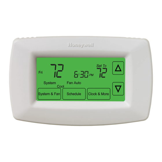
TH7000 Series
Touch-screen Programmable Thermostat
This manual covers the following models
• TH7220U:
For up to 2 Heat/1 Cool Heat Pumps or 2 Heat/2 Cool Conventional systems
(Pull thermostat from wallplate and turn over to find model number)
System Types
• Gas, oil, or electric heat with air
conditioning
• Warm air, hot water, highefficiency
furnaces, heat pumps, steam,
gravity
This thermostat contains a Lithium battery which may contain Perchlorate material.
Perchlorate Material—special handling may apply,
See www.dtsc.ca.gov/hazardouswaste/perchlorate
For assistance with this product please visit
or call Honeywell Customer Care toll-free at 1-800-468-1502
® U.S. Registered Trademark.
US Patents pending.
Copyright © 2011 Honeywell International Inc.
All rights reserved.
• Heat only — two-wire systems,
power to open and close
zone valves (Series 20), and
normallyopen zone valves
• Heat only with fan
• Cool only
• 750 mV heating systems
Need Help?
http://yourhome.honeywell.com
Installation
Guide
69-2668-03
Advertisement
Table of Contents

Related Manuals for Honeywell TH7000 Series


Summary of Contents for Honeywell TH7000 Series
- Page 1 This thermostat contains a Lithium battery which may contain Perchlorate material. Perchlorate Material—special handling may apply, See www.dtsc.ca.gov/hazardouswaste/perchlorate Need Help? http://yourhome.honeywell.com For assistance with this product please visit or call Honeywell Customer Care toll-free at 1-800-468-1502 ® U.S. Registered Trademark. US Patents pending. Copyright © 2011 Honeywell International Inc. All rights reserved. 69-2668-03...
- Page 2 Installation Guide Wallplate installation 1. Separate wallplate from thermostat. Grasp top and bottom of wallplate and pull to remove from thermostat. 2. Mount wallplate as shown below. Drill 3/16” holes for drywall. Drill 7/32” holes for plaster. M28073 Wire hole Mounting screws Wall anchors MCR31514 Must be installed by a trained, experienced technician • Read these instructions carefully. Failure to follow these instructions can damage the product or cause a hazardous condition. CAUTION: ELECTRICAL HAZARD Can cause electrical shock or equipment damage. Disconnect power before beginning installation.
-
Page 3: Terminal Designations
TH7000 Series Power options For 24VAC primary power, connect common side of transformer to “C” terminal. USED M28420 Insert supplied batteries for CONVENTIONAL primary or backup power. HEAT PUMP MCR31515 Wiring Remove factory-installed jumper Push excess wire back into the wall opening. only for two-transformer systems. Plug wall opening with non-flammable insulation. SCREW INSERT WIRES THEN TIGHTEN SCREWS WIRE HOLE USED... - Page 4 Installation Guide Wiring Wiring guide—conventional systems Shaded areas below apply only to TH7220. 1H/1C System (1 transformer) 1H/1C System (2 transformers) Power Power (cooling transformer) [1, 2] [R+Rc joined by jumper] Power (heating transformer) [1, 2] Heat relay Heat relay Compressor contactor Compressor contactor Fan relay Fan relay 24VAC common [3] 24VAC common [3, 4] Optional outdoor/remote sensor Optional outdoor/remote sensor Optional outdoor/remote sensor Optional outdoor/remote sensor...
- Page 5 TH7000 Series Wiring Wiring guide—heat pump systems Shaded areas below apply only to TH7220. 1H/1C Heat Pump (no auxiliary heat) 2H/1C Heat Pump (with auxiliary heat) Power Equipment monitor [6, 7] [R+Rc joined by jumper] Emergency heat relay Changeover valve Auxiliary heat relay (Heat 2)
-
Page 6: Set Date And Time
Installation Guide Set date and time Press Press to set time to set month, then press NEXT 10:10 2012 Repeat to set year and then day of month Done Go Back Next Done M27521 MCR31518 Press DONE to save changes. Press DONE to save and exit. Installer setup 1. - Page 7 TH7000 Series Setup functions Settings & Options (factory default in bold) Shaded areas below apply only to TH7220. 0120 Year 20 (2000-2099) (first two digits) 21 (2101-2178) 0130 Year 12 (2012) (second two digits) [Other options: 00-99] 0140 Month 6 [Other options: 1-12] 0150 Date 15 [Other options: 1-31]...
- Page 8 Installation Guide Installer setup Setup functions Settings & Options (factory default in bold) Shaded areas below apply only to TH7220. 0240 First stage heat Gas or oil furnaces of less than 90% efficiency cycle rate (CPH= Steam or gravity systems cycles per hour) 3 Hot water systems & furnaces of 90%+ efficiency 9 Electric furnaces [Other options: 2, 4, 6, 7, 8, 10, 11, 12 CPH]...
- Page 9 TH7000 Series Installer setup Setup functions Settings & Options (factory default in bold) 0500 Furnace filter change reminder 10-day run time (about 1 month) 30-day run time (about 3 months) 60-day run time (about 6 months) 4 90-day run time (about 9 months) 5 120-day run time (about 1 year) 6 365-day run time (about 3 years) 0510...
- Page 10 Installation Guide Installer system test Once you enter installer setup, press the Go Back button repeatedly until “Test” 1 appears. 0120 Go Back Next Done MCR31511 Test number System status EEEE Press change status Go Back Next Done MCR31520 Press Next to select next test. Press DONE to exit testing. Shaded areas below apply only to TH7220.
-
Page 11: Special Functions
TH7000 Series Special functions Shaded areas below apply only to TH7220. Auto Changeover (Setup Function 0300): When set to Auto, the thermostat automatically selects heating or cooling depending on the indoor temperature. Heat and cool settings must be at least 2 degrees apart. If function 0380 is set to On, the heat and cool settings must be at least 5 degrees apart. Remote Sensor (Setup Function 0340): If an optional outdoor sensor is installed, the thermostat can display the outside temperature. If an optional remote indoor sensor is installed, the thermostat will display the temperature at the sensor location (the internal sensor in the thermostat is not used). Adaptive Intelligent Recovery (Setup Function 0530): Allows the thermostat to “learn” how long the furnace and air conditioner take to reach programmed temperature settings, so the temperature is reached at the scheduled time. - Page 12 • 3-3/4” H x 6” W x 1-3/8” D • 99 mm H x 152 mm W x 35 mm D Need Help? http://yourhome.honeywell.com For assistance with this product please visit or call Honeywell Customer Care toll-free at 1-800-468-1502 Automation and Control Solutions Honeywell International Inc. 1985 Douglas Drive North Golden Valley, MN 55422 http://customer.honeywell.com ® U.S. Registered Trademark. US Patents pending. © 2011 Honeywell International Inc. 69-2668—03 M.S. 10-11 Printed in U.S.A.