Honeywell MICRONIK 200 R7426A Installation & Start-Up Instructions
Temperature controller with and without real-time clock
Hide thumbs
Also See for MICRONIK 200 R7426A:
- Specification data (8 pages) ,
- Installation & start-up instructions (17 pages)
Advertisement
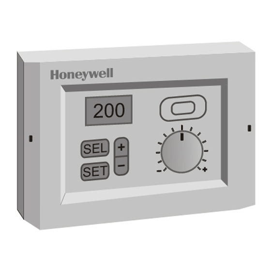
MicroniK 200
Fig. 1. Temperature Controller
Contents
General................................................................................ 1
Before Installation Note ....................................................... 1
Mounting.............................................................................. 1
Wiring .................................................................................. 2
Power Supply and Grounding.............................................. 2
Configuration and Control Parameters ................................ 3
Configuration Settings ......................................................... 6
Parameter Settings and Adjustment .................................... 8
Operating Overview............................................................11
Notes (with RTC, only)....................................................... 19
Copyright © 2007 Honeywell GmbH All Rights Reserved
TEMPERATURE CONTROLLER
WITH AND WITHOUT REAL-TIME CLOCK
INSTALLATION & START-UP INSTRUCTIONS
GENERAL
This document provides instructions and procedures for
installing and starting up the Micronik 200 R7426A,B,C
controllers. No special tools are required for mounting and
installation. The user interface and liquid-crystal display allow
accurate and easy parameter setting and output adjustment.
BEFORE INSTALLATION NOTE
•
Visually inspect equipment for shipping damage.
Report any damage to the appropriate Honeywell
representative.
•
Refer to job drawings for specific installation
information and mounting location.
•
Verify the controllers will be adequately separated
from the main power supply, relays, or other equip-
ment which can possibly generate electromagnetic
interference.
•
Verify that the ambient temperature and the humidity
at the controllers will not exceed 0...50°C (32...122°F)
and 5 to 95% rh.
•
Use shielded wiring in areas with high EMI.
•
All wiring should be separated from power lines by at
least 150 mm (6'').
•
Do not install controllers near frequency converters
or other high-frequency sources.
MOUNTING
The controllers can be mounted in an electric cabinet or other
suitable enclosure. They are suitable for back panel, DIN rail,
wall, or front panel mounting. The corresponding mounting
sequence, as well as dimensions and panel cut-out, are
illustrated in the mounting instruction sheet EN1B-0202GE51
supplied with the controllers.
If the compensation sensor signal (T3) is received from
another controller (parallel connection of compensation
sensor inputs), the jumper W303 has to be cut before
mounting the controller (see Fig. 2). This disconnects the
sensor from the internal power supply.
HONEYWELL
R7426A,B,C
EN1B-0203GE51 R0507C
Advertisement
Table of Contents

Related Manuals for Honeywell MICRONIK 200 R7426A


Summary of Contents for Honeywell MICRONIK 200 R7426A
-
Page 1: Table Of Contents
INSTALLATION & START-UP INSTRUCTIONS GENERAL This document provides instructions and procedures for installing and starting up the Micronik 200 R7426A,B,C controllers. No special tools are required for mounting and installation. The user interface and liquid-crystal display allow accurate and easy parameter setting and output adjustment. -
Page 2: Wiring
R7426A,B,C TEMPERATURE CONTROLLER WITH AND WITHOUT REAL-TIME CLOCK WIRING Screwless type, spring loaded terminals are provided on the controllers for panel and field wiring. These terminals are suitable for solid conductors as well as tinned or with multicore cable end, stranded wires up to 1.5 mm . -
Page 3: Configuration And Control Parameters
R7426A,B,C TEMPERATURE CONTROLLER WITH AND WITHOUT REAL-TIME CLOCK CONFIGURATION AND CONTROL PARAMETERS The controllers R7426A,B,C include two groups of settings (I and II) for control and configuration parameters that are automatically selected during programming. For parameter Ctrltyp = Lo, setting I is selected, and for parameter Ctrltyp = Hi1/Hi2, setting II is selected. - Page 4 R7426A,B,C TEMPERATURE CONTROLLER WITH AND WITHOUT REAL-TIME CLOCK config. par. default R7426 actual description setting value name A B C I / II C.12 T2ext Enable / Disables the T1 sensor input to be used for both T1 and T2 inputs. T2 installed T1 signal used for T2 C.13 LimTyp...
- Page 5 R7426A,B,C TEMPERATURE CONTROLLER WITH AND WITHOUT REAL-TIME CLOCK control par. setting I / setting II R7426 reso- actual unit description lution value no. name high def. A B C 50 / 21 / °C P.01 W1 Main setpoint for input T1 50 / 16 / °C...
-
Page 6: Configuration Settings
R7426A,B,C TEMPERATURE CONTROLLER WITH AND WITHOUT REAL-TIME CLOCK CONFIGURATION SETTINGS The controllers R7426A,B are supplied with unconfigured Table 6. Selection of CPA/SPA Type outputs to avoid damage of installed final control devices by CPA / SPA sensor / CPATYP supply of not applicable output signals if the controller power range remote setpoint unit type supply is turned on. - Page 7 R7426A,B,C TEMPERATURE CONTROLLER WITH AND WITHOUT REAL TIME CLOCK Output Signal Mode YMode (C.11) Supply of Temperature Signal T2 Sequence Operation T2ext (C.12) The controllers R7426B,C are supplied from the factory If sensor T1 is used also for high or low limit control, the con- configured for sequence operation of heating, mixed air, and figuration parameter T2ext must be set to 1.
-
Page 8: Parameter Settings And Adjustment
R7426A,B,C TEMPERATURE CONTROLLER WITH AND WITHOUT REAL TIME CLOCK Summer / Winter Time Change Default Programming DefProg (C.23) AddHour / SubHour (C.16 / C.17) Setting the control parameter DefProg to 1 resets all control and configuration parameters to defaults (see Table 4 and These configuration parameters are only available on Table 5). - Page 9 R7426A,B,C TEMPERATURE CONTROLLER WITH AND WITHOUT REAL TIME CLOCK Setting Guidelines for Proportional Band of P and limit or cascade sensor (T2) to operate the output device from full open (100%) to full closed (0%) or vice versa. P+I Control Xp1 is the throttling range for the main control loop, Xp2 is To estimate the proportional band (throttling range X ) for...
- Page 10 R7426A,B,C TEMPERATURE CONTROLLER WITH AND WITHOUT REAL TIME CLOCK Setting Guidelines for Reset Time of P+I Control Table 12. Calculation of summer/winter compensation outdoor air The reset time tr should be adjusted to 2...3 times of the control room temp. throttling temp.
-
Page 11: Operating Overview
R7426A,B,C TEMPERATURE CONTROLLER WITH AND WITHOUT REAL TIME CLOCK Y (%) If the controller is in OFF mode, the time schedule program overrides the minimum position by the ON/OFF input for plant/system shut off and the damper is driven into the fully closed position at OFF condition together with the heating and UNOCCUPIED cooling valve actuators. - Page 12 R7426A,B,C TEMPERATURE CONTROLLER WITH AND WITHOUT REAL TIME CLOCK Changing Operating Modes Fig. 7 shows the six operating modes. After power-up the Pushing the SET and SEL button simultaneously for approx. controller version is displayed and the controller enters the 1 sec causes the controller to leave the standard display standard display mode.
- Page 13 R7426A,B,C TEMPERATURE CONTROLLER WITH AND WITHOUT REAL-TIME CLOCK Time Out After approximately 10 min of inactivity (no button has been by the SET button are ignored by the controller and old pressed: time out), each mode returns automatically to parameter values will be retained. standard display mode.
- Page 14 R7426A,B,C TEMPERATURE CONTROLLER WITH AND WITHOUT REAL-TIME CLOCK Displaying Actual Values °C In the standard display mode, one of nine actual values, the actual time, or the date can be selected and displayed by pushing the SEL button. The icons of the permanently displayed controller mode are described in the following table: °C Table 13.
- Page 15 R7426A,B,C TEMPERATURE CONTROLLER WITH AND WITHOUT REAL-TIME CLOCK • To release the manual override (fixed) of the output, select the output, enter output adjustment mode and push the button simultaneously. Pushing the SEL button leads back to standard display mode. WITH MANUAL OVERRIDE IS ACTIVE...
- Page 16 R7426A,B,C TEMPERATURE CONTROLLER WITH AND WITHOUT REAL-TIME CLOCK Using the Schedules (with RTC, only) a normal day (day type = H0 is default). The function is Two schedules, one for programming the schedule points and described as follows: one for holiday programming, are available. •...
- Page 17 R7426A,B,C TEMPERATURE CONTROLLER WITH AND WITHOUT REAL-TIME CLOCK Selecting Clock and Schedules (with RTC, only) Programming Standard Schedule (with RTC, only) The standard schedule programming is used to program up to 6 schedule points for each weekday as well as for three DATE &...
- Page 18 R7426A,B,C TEMPERATURE CONTROLLER WITH AND WITHOUT REAL-TIME CLOCK Programming Holiday Schedule (with RTC, only) Interpreting Error Messages The holiday schedule programming is used to program each Different analog input errors can be identified by the controller day of the year (01.01 ... 31.12.) as a holiday (day type = H1, (Error handling).
-
Page 19: Notes (With Rtc, Only)
R7426A,B,C TEMPERATURE CONTROLLER WITH AND WITHOUT REAL-TIME CLOCK NOTES (WITH RTC, ONLY) Jan. Feb. March April June July August Sept. Oct. Nov. Dec. If the 29 of February is programmed to be a H1 or H2 holiday and the current year is not a leap year, this holiday will be deleted on March 1. - Page 20 Programmed controller mode (schedule mode) Table 17. Weekly schedule and holiday types Manufactured for and on behalf of the Environmental and Combustion Controls Division of Honeywell Technologies Sàrl, Ecublens, Route du Bois 37, Switzerland by its Authorized Representative: Automation and Control Solutions Honeywell GmbH Böblinger Straße 17...