Table of Contents
Advertisement
Quick Links
Owners &
Installation
LISTINGS AND CODE APPROVALS
These gas appliances have been tested in
accordance with AS4553-2000, NZS 5262
and have been certifi ed by the Australian Gas
Association for installation and operation as
described in these Installation and Operating
Instructions.
Your unit should be serviced annually by
an authorised service person.
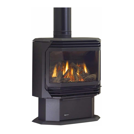
Freestanding Gas Stove
PLEASE KEEP THESE INSTRUCTIONS
FOR FUTURE REFERENCE
WARNING:
Improper installation, adjustment, altera-
tion, service or maintenance can cause
injury or property damage. Refer to this
manual. For assistance or additional in-
formation consult an authorized installer,
service agency or the gas supplier.
FOR YOUR SAFETY
Do not store or use gasoline or other fl am-
mable vapours and liquids in the vicinity of
this or any other appliance.
Installation and service must be performed
by an authorized installer, service agency or
the gas supplier.
918-533
Models: F37-NG
F37-LPG
FOR YOUR SAFETY
What to do if you smell gas:
Do not try to light any appli-
ance
Do not touch any electri-
cal switch: do not use any
phone in your building.
Immediately call your gas
supplier from a neighbour's
phone. Follow the gas sup-
plier's instructions.
If you cannot reach your
gas supplier, call the fi re
department.
05/18/06
Advertisement
Table of Contents

Related Manuals for Regency F37-LPG


Summary of Contents for Regency F37-LPG
- Page 1 Owners & Installation Freestanding Gas Stove Models: F37-NG F37-LPG PLEASE KEEP THESE INSTRUCTIONS FOR FUTURE REFERENCE WARNING: FOR YOUR SAFETY Improper installation, adjustment, altera- What to do if you smell gas: tion, service or maintenance can cause Do not try to light any appli- injury or property damage.
- Page 2 LPG of this series has been approved by AHD for both safety and effi ciency. As it also bears our own mark, it prom- ises to provide you with economy, comfort and security for many trouble free years to follow. Please take a moment now to acquaint yourself with these instructions and the many features of your Regency ®...
-
Page 3: Table Of Contents
Copy of the Lighting Plate instructions .......19 Before You Start ............5 General Safety Information ...........5 MAINTENANCE Installation Checklist ............6 Locating Your Regency Gas Stove ........6 Maintenance Instructions ..........20 Clearances to Combustibles .........6 General Flue Maintenance ..........20 Combustion and Ventilation Air ........6 Log Replacement ............20... -
Page 4: Data Badge
The NOTE: Regency ® units are constantly being each REGENCY Rear Flued Room Sealed data plate is located on the inside of the drop improved. Check the label on the unit and if Freestanding Gas Stove. We have printed a down pedestal door. -
Page 5: Installation
F37-NG is approved for use with 2) Installation and repair should be done YOUNG CHILDREN SHOULD BE ONLY by an authorised person. F37-LPG is approved for use with CAREFULLY SUPERVISED WHEN liquefi ed petroleum gases (LPG). THEY ARE IN THE SAME ROOM AS 3) DO NOT CONNECT TO MASONARY THE APPLIANCE. -
Page 6: Installation Checklist
Use the minimum clearances shown in the LOCATING YOUR be used in this appliance. diagrams below: REGENCY GAS STOVE F37-NG & F37-LPG Clearances 15) The appliance area must be kept clear and free of combustible materials, (gases and A Side Wall to Unit 190 mm When selecting a location for your stove, ensure other fl... -
Page 7: Exterior Flue Termination Locations
(IV) A fl ue terminal of this type shall not be located under a roofed area unless the roofed area is fully open on at least two sides and a free fl ow of air at the appliance is achieved. ® F37 Regency Rear Flued Room Sealed Freestanding Gas Heater... -
Page 8: Planning Your Flueing Installation
Rear Freestanding Gas Stoves (F37-NG and Vertical Termination with the Co-linear Flex and in your local building codes. F37-LPG) have been approved and listed as System are engineered products that have been Room Sealed heater systems by Australian designed and tested for use with the F37-NG, The gas appliance and fl... -
Page 9: Flueing Arrangements - Vertical Terminations
fl ue restrictor plate to the correct position. Tighten the screws. Vent Restrictor Vent Restrictor Vent Vent (fully open) Restrictor Restrictor Plate Plate ® F37 Regency Rear Flued Room Sealed Freestanding Gas Heater... -
Page 10: Residential And Manufactured Homes / Mobile Homes Installations
INSTALLATION RESIDENTIAL AND MANUFACTURED HOMES / MOBILE HOMES INSTALLATIONS You will require the following components with your new Regency ® Rear Flued Room Sealed Freestanding Gas Stove. Please review your product to make sure you have everything you need. In the event that you are missing any part, contact your dealer. - Page 11 Bend any remaining portion of the sheet metal strip back towards the fl ue cap and cut off any excess, it will be concealed by the decorative wall thimble cover. See diagram 5. Diagram 4 ® F37 Regency Rear Flued Room Sealed Freestanding Gas Heater...
-
Page 12: Vertical Termination With Co-Linear Flex System
Burner Inlet Orifi ce Sizes: NG LPG Burner Max. Input Rating 31.7 mj Min. Input Rating 16 mj Supply Pressure min. 1.13kPa min. 2.75kPa Manifold Pressure .89 kPa 2.55 kPa ® F37 Regency Rear Flued Room Sealed Freestanding Gas Heater... -
Page 13: Conversion From Ng To Lpg
15) Using the Allen wrench as shown in Fig.4, 24) Check for proper fl ame appearance and rotate the screw clock- glow on logs. wise until snug, do not overtighten. Fig.4 ® F37 Regency Rear Flued Room Sealed Freestanding Gas Heater... -
Page 14: Log Set Installation
Caution: Carbon will be produced if the air shutter is closed too much. Note: Any damage due to carboning result- Embers Embers ing from improperly setting the aera- tion controls is NOT covered under warranty. ® F37 Regency Rear Flued Room Sealed Freestanding Gas Heater... -
Page 15: Door Installation
Note: The door latch may require adjust- ment as the door gasket material compresses after a few fi res and after glass replacement. Turn the E)02-45 latch catch inward or outward. Notch Cutout Diagram 3 ® F37 Regency Rear Flued Room Sealed Freestanding Gas Heater... -
Page 16: Gas Pipe Pressure Testing
250-750 millivolt rated non- anticipator type thermostat that is CSA, ULC or UL approved may be used. CAUTION Do not connect the millivolt wall thermostat wires to the 240V wires. ® F37 Regency Rear Flued Room Sealed Freestanding Gas Heater... -
Page 17: Optional Remote Control
Before leaving this unit with the customer, the Switch the remote receiver to "remote" installer must ensure that the appliance is fi ring mode. The remote control is now ready for Use the Regency ® Remote Control Kit ap- correctly. This includes: operation. -
Page 18: Operating Instructions
"cracking" and "ticking" sounds will be and the unit cooled to below a useful heat output heard throughout the cycling process. range the fan will shut off automatically. ® F37 Regency Rear Flued Room Sealed Freestanding Gas Heater... -
Page 19: Copy Of The Lighting Plate Instructions
OPERATING INSTRUCTIONS COPY OF THE LIGHTING PLATE INSTRUCTIONS Gas Inlet ® F37 Regency Rear Flued Room Sealed Freestanding Gas Heater... -
Page 20: Maintenance
fl ow of combustion and Note: If you have an incorrect fl ame pat- replacement log. The position of these logs ventilation air is not obstructed. tern, contact your Regency ® dealer must be as shown in the diagram under Log for further instructions. -
Page 21: Latch Adjustment
GLASS REPLACEMENT retainers and fasten with the nuts but do not overtighten, as this can break the glass. Note: the door catch plate fi ts on top of the Your Regency ® stove is supplied with high tem- left side retainer. -
Page 22: Fan Maintenance
1) Unplug or disconnect power source to stove. 2) Remove the rear access panel on the back of the stove. The fan can only be accessed from the back of the stove. ® F37 Regency Rear Flued Room Sealed Freestanding Gas Heater... - Page 23 10) To replace the burner tray assembly, simply reverse these instructions. 7) Remove burner. See diagram below. Note: Use a magnetic type screwdriver if possible. 8) Remove all 18 screws holding the burner tray assembly in place. ® F37 Regency Rear Flued Room Sealed Freestanding Gas Heater...
-
Page 24: Parts List
Thermodisc Cover 19) 730-530 Side Panel Door Assy (Right Side) 20) 730-525 Side Panel Door Assy (Left Side) 21) 560-031 Side Panel Door Hinge 23) 904-258 Side Panel Door Magnet ® F37 Regency Rear Flued Room Sealed Freestanding Gas Heater... -
Page 25: Burner & Log Assembly
Middle Right Log Pilot Holder Middle Left Log W840470 Pilot Assembly Gasket Front Right Log 730-935 Log Set Front Left Log 730-528 Log Stand 904-390 Pilot Orifi ce #52 - LPG ® F37 Regency Rear Flued Room Sealed Freestanding Gas Heater... -
Page 26: Door Assemblies
Door Gasket Kit 105) Ceramic Paper 106) 940-323/P Side Glass 107) 936-243 Glass Gasket 108) 940-322/P Centre Glass 111) Door Frame Fibre Paper 112) 750-015 Door Glass Extrusion 208) 940-325/P Wrap Glass ® F37 Regency Rear Flued Room Sealed Freestanding Gas Heater... -
Page 27: Warranty
The warranty does not extend to any part or parts which show evidence of misuse or abuse, neglect, accident, lack of maintenance, or improper installation. Products made by other manufacturers and used in conjunction with the operation of this appliance without authorization from Regency ®... - Page 28 Printed in Canada © Copyright 2006, FPI Fireplace Products International Ltd. All rights reserved.