Table of Contents
Advertisement
Quick Links
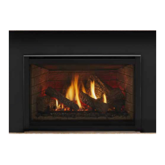
Model:
QV36DC-A
•
Important operating and
maintenance instruc-
tions included.
WARNING: If the information in these
instructions is not followed exactly, a fi re
or explosion may result causing property
damage, personal injury, or death.
• Do not store or use gasoline or other fl am-
mable vapors and liquids in the vicinity of
this or any other appliance.
• What to do if you smell gas
- Do not try to light any appliance
- Do not touch any electrical switch. Do not
use any phone in your building.
- Immediately call your gas supplier from a
neighbor's phone. Follow the gas suppli-
er's instructions.
- If you cannot reach your gas supplier, call
the fi re department.
• Installation and service must be performed
by a qualifi ed installer, service agency, or the
gas supplier.
This appliance may be installed as an OEM installation in
manufactured home (USA only) or mobile home and must be
installed in accordance with the manufacturer's instructions
and the manufactured home construction and safety standard,
Title 24 CFR, Part 3280 or Standard for Installation in Mobile
Homes, CAN/CSA Z240MH.
This appliance is only for use with the type(s) of gas indicated
on the rating plate.
R
CAUTION
DO NOT DISCARD THIS MANUAL
•
Read, understand and follow
these instructions for safe
installation and operation.
Quadra-Fire • QV36DC-A • 2161-900 Rev. B • 10/08
Owner's Manual
Installation and Operation
•
Leave this manual with
party responsible for use
and operation.
WARNING
HOT SURFACES!
Glass and other surfaces are hot during
operation AND cool down.
Hot glass will cause burns.
• DO NOT touch glass until it is cooled
• NEVER allow children to touch glass
• Keep children away
• CAREFULLY SUPERVISE children in same room as
fi replace.
• Alert children and adults to hazards of high temperatures.
High temperatures may ignite clothing or other fl ammable
materials.
• Keep clothing, furniture, draperies and other fl ammable
materials away.
This appliance has been supplied with an integral barrier
to prevent direct contact with the fi xed glass panel. DO
NOT operate the appliance with the barrier removed.
Contact your dealer or Hearth & Home Technologies if the
barrier is not present or help is needed to properly install one.
In the Commonwealth of Massachusetts installation must be
performed by a licensed plumber or gas fi tter.
See Table of Contents for location of additional Commonwealth
of Massachusetts requirements.
Installation and service of this appliance should be
performed by qualifi ed personnel. Hearth & Home
Technologies suggests NFI certifi ed or factory-trained
professionals, or technicians supervised by an NFI
certifi ed professional.
1
Advertisement
Table of Contents

Related Manuals for Quadra-Fire QV36DC-A


Summary of Contents for Quadra-Fire QV36DC-A
-
Page 1: What To Do If You Smell Gas
Technologies suggests NFI certifi ed or factory-trained This appliance is only for use with the type(s) of gas indicated professionals, or technicians supervised by an NFI on the rating plate. certifi ed professional. Quadra-Fire • QV36DC-A • 2161-900 Rev. B • 10/08... -
Page 2: Safety And Warning Information
Young children should be CAREFULLY DO NOT place furniture or any other combustible SUPERVISED when they are in the same room as household objects within 36 inches of the fi replace the appliance. front. Quadra-Fire • QV36DC-A • 2161-900 Rev. B • 10/08... -
Page 3: Table Of Contents
Step 13 Climate Control .............34 After the Installation ..............34 Section 4: Maintaining and Servicing Your Fireplace....34 Section 5: Troubleshooting............35 Limited Lifetime Warranty............37 Contact Information ..............39 = Contains updated information. Quadra-Fire • QV36DC-A • 2161-900 Rev. B • 10/08... -
Page 4: Service Parts Lists
QV36DC-A Service Parts Service Parts Diagram Beginning Manufacturing Date: Apr 2008 Ending Manufacturing Date:______ Log Set Assembly Quadra-Fire • QV36DC-A • 2161-900 Rev. B • 10/08... - Page 5 Conversion Kit NG NGKS-QV36DC Conversion Kit LP LPKS-QV36DC Regulator NG 230-1570 Regulator LP 230-1520 Pilot Orifi ce NG 2103-116 Pilot Orifi ce LP 2103-117 Additional service part numbers appear on following page. Quadra-Fire • QV36DC-A • 2161-900 Rev. B • 10/08...
- Page 6 Valve NG 230-0710 Valve LP 230-0720 Valve Bracket 2118-104 Flex Ball Valve Assembly 302-320A Control Panel 291-125 Piezo Ignitor 291-513 Pilot Control Knob 571-534 Flame Control Knob 571-533 ON/OFF Rocker Switch 060-521A Quadra-Fire • QV36DC-A • 2161-900 Rev. B • 10/08...
-
Page 7: Section 1: Approvals And Codes
• A 110-120 VAC circuit for this product must be protected room in the U.S.A. and Canada. with ground-fault circuit-interrupter protection, in compliance with the applicable electrical codes, when it is installed in locations such as in bathrooms or near sinks. Quadra-Fire • QV36DC-A • 2161-900 Rev. B • 10/08... -
Page 8: Requirements For The Commonwealth Of Massachusetts
VENT DIRECTLY BELOW. KEEP CLEAR OF ALL OB- of the installation. STRUCTIONS”. See Gas Connection section for additional Common- wealth of Massachusetts requirements. Quadra-Fire • QV36DC-A • 2161-900 Rev. B • 10/08... -
Page 9: Section 2: Getting Started
The Hearth & Home Technologies Warranty will be voided by, and Hearth & Home Technologies disclaims any Quadra-Fire direct vent gas fi replaces are designed to op- responsibility for, the following actions: erate with all combustion air siphoned from outside of the •... - Page 10 [55mm] [90mm] 36 1/8 [916mm] 12 3/4 [323mm] 41 1/8 6 7/8 [174mm] [1044mm] STANDOFFS HOOD RATING PLATE AND LABELS ELECTRICAL ACCESS LINE ACCESS CONTROLS Figure 1. Diagram of the QV36DC-A Quadra-Fire • QV36DC-A • 2161-900 Rev. B • 10/08...
-
Page 11: Section 3: Installing The Fireplace
Sides........1 ....25 extending past the face of the fi replace is one inch (25 mm). The back of the fi replace may be recessed 21 1/2 inches (546 mm) into combustible construction. Quadra-Fire • QV36DC-A • 2161-900 Rev. B • 10/08... -
Page 12: Step 2 Framing The Fireplace
The center of the hole is one (1) inch (25.4mm) above the center of the horizontal vent pipe. 0” CLEARANCE TO 0” CLEARANCE FRAMING MEMBER Quadra-Fire • QV36DC-A • 2161-900 Rev. B • 10/08... - Page 13 7-1/4 1-1/4 TYP DVP48 1/2 TYP 8-9/16 12-9/16 NOTE: PIPES OVERLAP 1-1/4 INCHES AT EACH JOINT. Figure 4. DVP-Series Direct Vent Component Specifi cations (5-inch inner pipe / 8-inch outer pipe) Quadra-Fire • QV36DC-A • 2161-900 Rev. B • 10/08...
-
Page 14: Step 3 Installing The Vent System
ELBOW CEILING FIRESTOP Terminations Kits (Required to have a minimum of 3 feet of vertical in the vent system) DVP-TRAP SERIES DVP-TVHW DVP-TB1 Figure 5. Vent System Components and Termination Kits Quadra-Fire • QV36DC-A • 2161-900 Rev. B • 10/08... - Page 15 Straight Up Vertical Venting Adjustable Flue Restrictor (see Figure 8). Flue Restrictor Instructions 1. Remove screws with a 1/4 nut driver. Adjust to desired position per table. See Flue Restricting chart. Figure 8 Quadra-Fire • QV36DC-A • 2161-900 Rev. B • 10/08...
- Page 16 ELBOW Figure 9. Horizontal Installation NOTE: This model is tested and approved to use 45° elbows in corner installations. However, 90° elbows will result in better performance. Figure 10. Corner Installation Quadra-Fire • QV36DC-A • 2161-900 Rev. B • 10/08...
- Page 17 3-feet (914mm). the fi replace before a 90 elbow, to allow the vent pipe to clear the top standoffs. Figure 12. Venting with One 90° Elbow Quadra-Fire • QV36DC-A • 2161-900 Rev. B • 10/08...
- Page 18 3’ MIN. (914mm) 15´ MAX. (4.65m) 4’ MIN. (1.22m) 20´ MAX. (6.2m) V+H+H = 40’ MAX.(12.4m) = 20´ MAX. (6.2m) +H = 40’ MAX.(12.4m) Figure 14. Venting with Two 90° Elbows Quadra-Fire • QV36DC-A • 2161-900 Rev. B • 10/08...
- Page 19 4´MIN. (1.22m) 8´MAX. (2.48m) 20´MAX. (6.2m) V+H+H = 40 MAX. (12.4 m) H = 8´ MAX. (2.48 m) = 20´ MAX. (6.2 m) ´ Figure 15. Venting with three 90° elbows Quadra-Fire • QV36DC-A • 2161-900 Rev. B • 10/08...
- Page 20 3’ MIN. (914mm) 15’ MAX. (4.65m) 4’ MIN. (1.22m) 20’ MAX. (6.2m) H +H = 20’ MAX. (6.2m) +H +H = 40’ MAX. (12.4m) NOTE: Figure 16. Venting with three 90° elbows Quadra-Fire • QV36DC-A • 2161-900 Rev. B • 10/08...
-
Page 21: Installing Vent Components
WARNING: INSTALLATION OF THIS FIRE- gasket material. PLACE REQUIRES THE USE OF A HEAT SHIELD ABOVE THE FIRST 90 ELBOW IN HERE THE VENTING SYSTEM. Figure 17. Quadra-Fire • QV36DC-A • 2161-900 Rev. B • 10/08... - Page 22 CORRECT INCORRECT COMBUSTIBLE SURFACE 4. Install Support Brackets Refer to Cinch Pipe and Termination Cap installation in- DIRECTION structions. HEAT SHIELD ° ELBOW Figure 20. Figure 22. Adding Venting Components Quadra-Fire • QV36DC-A • 2161-900 Rev. B • 10/08...
- Page 23 SHIELD IF TOO NOTE: There must be NO INSULATION or other SHORT combustibles inside the framed fi restop opening. EXTERIOR FIRESTOP INTERIOR FIRESTOP Figure 24. Heat Shield, Interior & Exterior Firestops Quadra-Fire • QV36DC-A • 2161-900 Rev. B • 10/08...
-
Page 24: Vent Termination
fi restop opening. SEE VENT TERMINATION MINIMUM CLEARANCES DIAGRAM ON FOLLOWING PAGE. JOIST CEILING NAILS (4 REQUIRED) CEILING FIRESTOP Figure 28. 7 1/4” (184mm) Figure 26. Ceiling Firestop (Ceiling Side) Trapezoid Termination Cap Quadra-Fire • QV36DC-A • 2161-900 Rev. B • 10/08... - Page 25 Figure 4.4 Minimum Clearances for Termination CAUTION: IF EXTERIOR WALLS ARE FINISHED WITH VINYL SIDING, IT IS SUGGESTED THAT A VINYL PROTECTOR KIT BE INSTALLED. Quadra-Fire • QV36DC-A • 2161-900 Rev. B • 10/08...
- Page 26 11/12 to 12/12 over 12/12 to 14/12 over 14/12 to 16/12 over 16/12 to 18/12 over 18/12 to 20/12 over 20/12 to 21/12 Figure 30. Minimum Height from Roof to Lowest Discharge Opening Quadra-Fire • QV36DC-A • 2161-900 Rev. B • 10/08...
-
Page 27: Step 4 Positioning, Leveling, And Securing The Fireplace
• Shim the fi replace with non-combustible material, such as sheet metal, as necessary. • Secure the fi replace to the framing by nailing or screw- ing. Figure 32. Gas Control System Quadra-Fire • QV36DC-A • 2161-900 Rev. B • 10/08... -
Page 28: Step 6 The Gas Supply Line
The fi replace must be isolated from the gas supply piping system by closing its individual shut-off valve during any pressure testing of the gas supply piping system at test pressures equal to or less than one-half (1/2) psig (3.5 kPa). Quadra-Fire • QV36DC-A • 2161-900 Rev. B • 10/08... -
Page 29: Step 8 Wiring The Fireplace
MUST BE REPLACED, IT MUST BE ° REPLACED WITH TYPE 105 C RATED WIRE. JUNCTION BOX BLOWER RECEPTACLE GROUND TEMPERATURE SENSOR SWITCH BLOWER SENSOR BLOWER SWITCH 110-120 VAC “FAN” RECEPTACLE SPEED CONTROL Quadra-Fire • QV36DC-A • 2161-900 Rev. B • 10/08... -
Page 30: Step 9 Finishing
NOTE: There are 3 metal tabs holding the non-combustible board in place for shipping. These tabs are to be cut off or bent back before fi nishing around the fi replace front. Quadra-Fire • QV36DC-A • 2161-900 Rev. B • 10/08... -
Page 31: Step 10 Installing Trim, Logs, And Ember Material
Position the left wall all the way back against the back wall. Using the retaining clip and screw included, secure the side wall refractory as shown (see Figures 39 and 40). Figure 42. Quadra-Fire • QV36DC-A • 2161-900 Rev. B • 10/08... -
Page 32: Positioning The Logs
You’ve reviewed all safety warnings, you’ve checked the appliance for gas leaks, you know the vent system is unobstructed, and you’ve checked for faulty components. Now you’re ready to light the appliance. Quadra-Fire • QV36DC-A • 2161-900 Rev. B • 10/08... -
Page 33: Step 12 Lighting The Appliance
This will help avoid setting operation or longevity of your fi replace. off smoke detectors, and help eliminate any odors associated with the fi replace’s initial burning. Quadra-Fire • QV36DC-A • 2161-900 Rev. B • 10/08... -
Page 34: Step 13 Climate Control
Make sure the fl ames are steady - not lifting or fl oating. See Figure 44. The thermopile/thermocouple tips Figure 44. Burner Flame Patterns should be covered with fl ame (See Figure 32). Quadra-Fire • QV36DC-A • 2161-900 Rev. B • 10/08... -
Page 35: Section 5: Troubleshooting
With the pilot in the ON position, disconnect the thermopile leads from the valve. Take a reading at the thermopile leads. The read- ing should be 325 millivolts minimum. Replace the thermopile if the reading is below the minimum. Quadra-Fire • QV36DC-A • 2161-900 Rev. B • 10/08... - Page 36 Ensure that the glass is tightened properly on the unit, particularly on top corners. Quadra-Fire • QV36DC-A • 2161-900 Rev. B • 10/08...
-
Page 37: Limited Lifetime Warranty
• In no event shall HHT be liable for any incidental or consequential damages caused by defects in the product. • Adjustments, regular maintenance, cleaning and temporary repairs, or the failure to duplicate the problem in the home is not covered under this warranty. Page 1 of 2 4021-645A 09-01-08 Quadra-Fire • QV36DC-A • 2161-900 Rev. B • 10/08... - Page 38 If warranty service is needed, you should contact your installing dealer. If the installing dealer is unable to provide necessary parts or components, contact the nearest authorized HHT dealer or supplier. Page 2 of 2 4021-645A 09-01-08 Quadra-Fire • QV36DC-A • 2161-900 Rev. B • 10/08...