Advertisement
Quick Links
UNIVERSAL GARAGE DOOR
KEYLESS ENTRY SYSTEM
MODELS KEP-1 AND KEP-1A
INSTALLATION AND
OPERATING INSTRUCTIONS
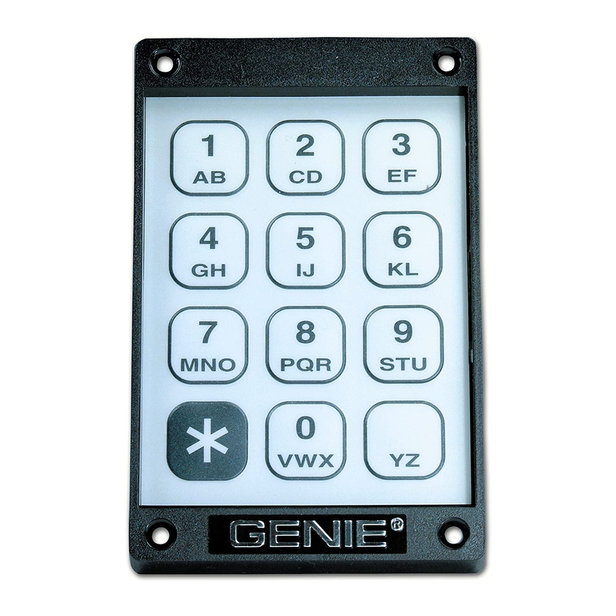
The Genie® Keyless Entry System includes everything required for most
residential garage installations. The contents include the code pad with
signal tail, control box, wall transformer, two (2) 25' rolls of wire and a
parts bag containing insulated staples and fasteners.
1
2
3
4
5
6
7
8
9
Transformer
*
0
#
Code Pad
Control Box
SAFETY CAUTION
Prior to installing the Keyless Entry System, be certain to disconnect
the electrical power to the garage door opener. Most garage door
openers feature a manual release device. Since automatic operation
of the door will not be possible after power is disconnected, we
suggest you disengage the opener per the manufacturer's
instructions. This will allow manual operation of the garage door
during installation of the Keyless Entry System.
The Genie® Company
1 Door Drive
Mt. Hope, OH 44660
For help call 1-800-654-3643
2242923617
2-Conductor Wire (2)
Parts Bag
INSTALLATION
1. Select a convenient location for the code pad on the outside door jamb or
wall. BE CERTAIN THE LOCATION IS OUT OF THE AREA OR PATH OF THE
MOVING GARAGE DOOR AND SUPPORTING HARDWARE.
Figure 1 illustrates the code pad installed on the door jam. A wall installation is
illustrated in Figure 2. IMPORTANT: Do not allow children to play games with
the door.
Door
Jam
Code
Pad
3
1
2
6
5
Door
4
9
8
#
7
0
*
Stop
Figure 1
2. For door jam mounting, momentarily pry the door stop away from the jam and
slide the signal tail between and into the garage, Figure 3. Secure the code pad
to the jam with the four brass screws supplied. CAUTION: JAM MOUNTING
SHOULD NOT BE USED FOR ONE-PIECE GARAGE DOORS. For wall mounting,
drill a 1/2" hole through the garage wall at the selected location. Carefully
insert the signal tail through the hole and into the garage., Figure 4. Be sure you
route all connecting wire away from the garage door to ensure it cannot be
snagged by the door or door hardware. Secure the code pad to the wall with
the four brass screws supplied.
Door Jam
Door
Stop
1
2
3
4
5
6
7
8
9
*
0
#
Garage
Interior
Figure 3
3. Remove the cover of the control box by pressing inward on the sides and
pulling up. The signal tail plugs into the control box, therefor, position the box
on the interior wall of the garage within reach of the signal tail. Proper
positioning is illustrated in Figure 5. Secure the control box with the two
1" screws supplied.
Outside
Garage
Wall
Code
Pad
3
6
2
5
1
9
4
8
#
7
0
*
Figure 2
Outside
Garage
Garage
Door
Wall
Signal
Signal
Tail
Tail
1
2
3
4
5
6
7
8
9
*
0
#
Figure 4
1/2" hole
Advertisement

Related Manuals for Genie KEP-1

Summary of Contents for Genie KEP-1
-
Page 1: Operating Instructions
Door OPERATING INSTRUCTIONS Stop The Genie® Keyless Entry System includes everything required for most residential garage installations. The contents include the code pad with signal tail, control box, wall transformer, two (2) 25' rolls of wire and a parts bag containing insulated staples and fasteners. - Page 2 Control Box Transformer 1) You may obtain service from a Genie dealer or dealers listed under the door section of your yellow pages. The Genie Company will in-warranty parts at no charge, however, those dealers are independent businesses and may render a bench or service call charge for their services. The Genie Push button terminals Company will not be responsible for these charges.