Williams 3144030 Owner's Manual
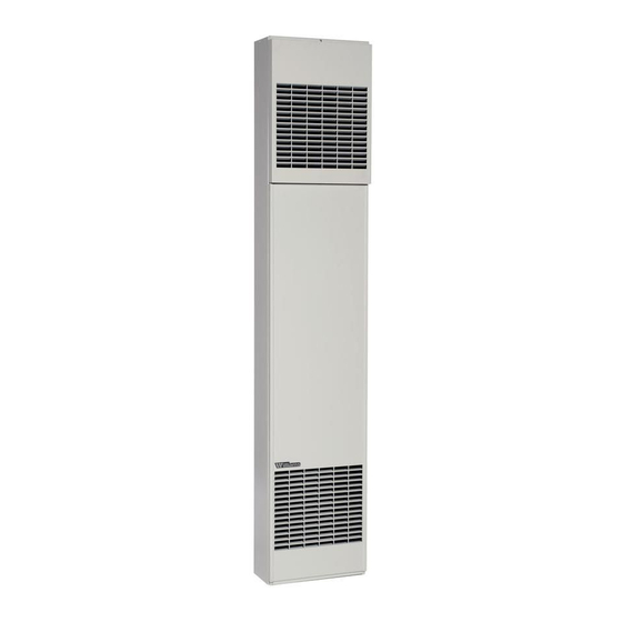
Electric counterflow wall furnace
Hide thumbs
Also See for 3144030:
- Brochure & specs (2 pages) ,
- Brochure & specs (2 pages) ,
- Owner's manual (20 pages)
Table of Contents
Advertisement
OPERATING
INSTRUCTIONS
& PARTS MANUAL
ELECTRIC COUNTERFLOW
owner's
manual
MODEL
NO.
3144030
137T
ft. Unpacking
_ Installation
Operation
= _"r,=ir Parts
_
This Manual For
_
,lt _e2Lerence.
WALL FURNACE
READ THIS OWNERS
MANUAL
CAREFULLY
BEFORE YOU INSTALL
YOUR NEW WILLIAMS
WALL FURNACE
I
FAILURE TO COMPLY WITH INSTRUCTIONS
I
I
COULD RESULT IN PERSONAL INJURY,
PROPERTY DAMAGE AND/OR DEATH.
FOR YOUR SAFETY
J
WARNING: DO NOT STORE OR USE GASOLINE
OR OTHER FLAMMABLE VAPORS AND LIQUIDS
IN THE VICINITY
OF THIS OR ANY OTHER
APPLIANCE.
IF YOU SMELL SMOKE:
DANGER OF ELECTRICAL SHOCK
1. DO NOT TOUCH FURNACE!
2 IMMEDIATELY SHUT DOWN MAIN
ELECTRICAL SUPPLY TO FURNACE.
3. EXTINGUISH
ANY OPEN FLAME
4 CALL YOUR LOCAL WILLIAMS SERVICE
CENTER.
.........
lilT
1
=
i
r
ilT'i
r
Williams
Furnace
Co., 225 Acacia
St., Colton,
CA 92324
PRINTED IN USA 11/96
P321008
Advertisement
Table of Contents

Related Manuals for Williams 3144030


Summary of Contents for Williams 3144030
- Page 1 IF YOU SMELL SMOKE: DANGER OF ELECTRICAL SHOCK 1. DO NOT TOUCH FURNACE! 2 IMMEDIATELY SHUT DOWN MAIN ELECTRICAL SUPPLY TO FURNACE. 3. EXTINGUISH ANY OPEN FLAME 4 CALL YOUR LOCAL WILLIAMS SERVICE This Manual For CENTER. ,lt _e2Lerence..lilT ilT'i...
-
Page 2: Your Warranty
Introduction Your Warranty ........ Surface Mount Installation ....7 - 8 Williams Installation Policy ...... Thermostat Installation ....... 8 - 9 Williams Installation Warranty ....Mounting Your Furnace ......Introduction ........Optional Rear Outlet Installation ....Basic Description ......Electrical Wiring ...... -
Page 3: Basic Description
Introduction Always consult your local Heating Inspector, Building Please read our instructions before you install and use Department or Electric Utility company regarding regula- your furnace. This will help you obtain the full value from tions, codes or ordinances which apply to the installation this furnace. - Page 4 Basic Materials Electrical wiring supplies as needed. Use copper wire only. For supply connections use 6 AWG or larger wires suitable 2" x 4" x (length as required) (See close off stud space, for at least 60 C (140 F). page 7).
- Page 5 Optional Accessories Trip Strip Kit 4701 10 inches of furnace. Built-in damper lets you shut off air flow to second room if desired. Provides finished edge at sides of wall furnace. Neutral beige enamel steel. Rear Outlet Kit 6501 Lets you route some heated air to a second room behind the furnace, Finished wall of second room must be within Installing Your Wall Furnace...
- Page 6 Recessed Mount Installation BEFORE YOU BEGIN: To avoid electrical shock, turn off ELECTRICAL SUPPLY ROUGH-IN electrical circuits that pass through the wall where you To properly route the conduit, electrical power supply are going to install the furnace. wires and the thermostat wiring to furnace top, you can If you intend to use the optional rear outlet, turn to page make entry holes in the ceiling wall plate above the furnace.
-
Page 7: Mount Installation
Recessed Mount Installation (Con't) NOTE CLOSE OFF STUD SPACE Flexible conduit may be used only if approved by your local codes and ordinances. If you have any doubt, consult your local Electrical or Building Inspector. STUD PLATE 5. The electrical supply wires, ground wire and the... -
Page 8: Mounting The Thermostat
Surface Mount Insta!lation (Con't) NOTE 7. Be sure to leave enough excess wire at the furnace to make the connections inside the furnace junction box. Flexible conduit may be used only ifapproved by your local codes and ordinances. If you have any doubt, consult your 8. - Page 9 Thermostat Installation (Con't) bring room temperature up to the desired level. The heat HEAT ANTICIPATOR - TYPICAL anticipator thus makes it possible to maintain very close temperature control. USE THIS LEVER ADJUSTINDICATOA NOTE Refer to installation instructions packed in the thermostat carton if you have any doubt about the above procedures.
- Page 10 Optional Rear Outlet Installation RECESSED MOUNT FURNACE 1. Cut 8-1/4 inch x 12-1/4inch hole in wall as shown in Fig. 3, page 6. 2. Cut 8 inch x 12 inch opening in back of cabinet follow- ing scored lines stamped on the cabinet. See Fig. 4, page 6.
-
Page 11: Wire Connection
Electrical Wiring WARNING Connect the thermostat wires to the two (thermostat) wires extending inside the junction box. Refer to wiring diagram DANGER OF PROPERTY DAMAGE, on junction box cover plate and Fig. 12. BODILY INJURY OR DEATH. When furnace mounting has been completed, see steps TURN OFF ELECTRIC POWER AT FUSE BOX OR 1, 2 and 3 below. - Page 12 Trim TRIM STRIP KIT 4701 NOTE When desired, optional Trim Strip Kit may be used to cover Quarter-round wood molding may be used for trim if the crack between furnace and wall. See Fig. 13. desired, which may be painted to match the wall, Place strips tight against furnace with other edge against TRIM COVER (SURFACE MOUNT) wall surface and fasten to wall with escutcheon pins pro-...
- Page 13 Operating Your Furnace The heater is controlled by means of 24 volt wall-mounted tect against excessive and prolonged current surges. If these protectors open the heating circuit, the heat limiter thermostat. When the thermostat circuit is energized, low must be replaced by your Service Technician who will voltage relays are a3tuated which close circuits to heating determine and correct the cause of failure.
-
Page 14: Specifications
WIRING DIAGRAM MODEL 3144030 LADDER DIAGRAM CONNECTION DIAGRAM JUN C'i]0N BOX 1_24OV 60Hz 1 pHAS_£ R_J_Y COt_TACT E3_NT-1 FUSIBLE UNK -c__ CONTACT E]_4D_ T--2 FUSIBLE UNK REI._Y COiL 92_RE Furnace Technical Information SPECIFICATIONS & DIMENSIONS MOTOR & FAN DATA Volts... - Page 15 WILLIAMS ELECTRIC COUNTERFLOW WALL FURNACE REPAIR PARTS FOR MODEL -- 3144030 FURNACE ASSEMBLY USE ONLY MANUFACTURERS AUTHORIZED PARTS FOR PARTS LIST SEE PAGE 16 m15--...
- Page 16 WILLIAMS ELECTRIC COUNTERFLOW WALL FURNACE REPAIR PARTS MODEL 3144030 REF. DESCRIPTION PART OUTER CASING 16C01 TOP FRONT PANEL 16BO1 BOTTOM FRONT PANEL 16B09 TOP TRIM COVER 16A07 ELEMENT COVER 16A04 JUNCTION BOX ASSEMBLY 16B15 ELEMENT CASING BODY ASSEMBLY 16C04 MOTOR...
- Page 17 Service Record DATE MAINTENANCE PERFORMED COMPONENTS REQUIRED...
- Page 18 Service Record DATE MAINTENANCE PERFORMED COMPONENTS REQUIRED...
- Page 19 Service Record DATE MAINTENANCE PERFORMED COMPONENTS REQUIRED...
- Page 20 When ordering repair parts, always give the following ment supplier. information: 1 MODEL NUMBER The Model Number of your Williams wall furance will be DATE CODE found on the rating plate. 3 PART NUMBER PART DESCRIPTION WILLIAMS FURNACE COMPANY MANUFACTURED 225 Acacia Street IN THE U.S.A.