Table of Contents
Advertisement
Quick Links
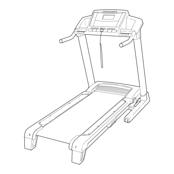
Model No. NTL11806.0
Serial No.
Write the serial number in the space
above for reference.
Serial Number /
Decal
QUESTIONS?
As a manufacturer,
we
are corn =
mitted to providing complete
customer satisfaction.
If you
have questions,
or if parts are
damaged or missing,
PLEASE
CONTACT OUR CUSTOMER
SERVICE DEPARTMENT
DI RECTLY.
CALL TOLL=FREE:
1-888-825-2588
Mon.-Fri.,
6 a.m.-6 p.m. MST
ON THE WEB:
www.nordictrackservice.com
'S
UAL
www.nordictrack.com
new products,
prizes,
fitness tips, and much more!
Advertisement
Table of Contents

Related Manuals for NordicTrack Viewpoint 3000 NTL11806.0


Summary of Contents for NordicTrack Viewpoint 3000 NTL11806.0
- Page 1 If you have questions, or if parts are damaged or missing, PLEASE CONTACT OUR CUSTOMER SERVICE DEPARTMENT DI RECTLY. CALL TOLL=FREE: 1-888-825-2588 Mon.-Fri., 6 a.m.-6 p.m. MST ON THE WEB: www.nordictrackservice.com www.nordictrack.com new products, prizes, fitness tips, and much more!
-
Page 2: Table Of Contents
OPERATION AND ADJUSTMENT ............HOW TO FOLD AND MOVE THE TREADMILL ..........TROUBLESHOOTING ..............CONDiTiONiNG GUiDELiNES ............... PART LiST ................ORDERING REPLACEMENT PARTS ............EXPLODED DRAWING ..............LiMiTED WARRANTY ............... Back Cover NordicTrack is a registered trademark of iCON IP, inc. -
Page 3: Important Precautions
AND MOVE THE TREADMILL on page 27.) You page 14. To purchase a surge suppressor, must be able to safely lift 45 pounds (20 kg) to your local NordicTrack dealer or call the toll- raise, Jower, or move the treadmill. free telephone... - Page 4 21. Do not change the incline of the treadmill or other electric light or power circuits, placing objects under the treadmill. where it can fall into such power lines or cir- cuits. When installing an outside antenna sys= 22. When folding or moving the treadmill, make tern, extreme...
- Page 5 iiiiiiiiiiiiiiiiiiii Ground Standoff Clam Insulators Service To External Antenna Conductors Terminal of Treadmill Antenna Service Lead-in Wire Entrance Antenna Equipment Wire Discharge Unit Ground Wire Power Service Grounding Electrode System (e.g. Ground Bonding 3round Interior Metal Water Pipe) Clamps Jumper Clamps Optional Antenna Grounding Electrode Driven 8 Feet (2.44m) Into The Earth (If Required...
-
Page 6: Before You Begin
BEFORE YOU BEGIN Thank you for selecting the revolutionary NordicTrack ® ing this manual, please see the front cover of this man- VIEWPOINT 3000 treadmill. The VIEWPOINT 3000 ual. To help us assist you, note the product model treadmill offers a selection of features designed to number and serial number before contacting us. -
Page 7: Assembly
ASSEMBLY Assembly requires two persons. Set the treadmill in a cleared area and remove all packing materials. Do not dispose of the packing materials until assembly is completed. Note: The underside of the treadmill walking belt is coated with high-performance lubricant. - Page 8 Attach twoBasePads(81)tothebaseofthe Uprights (85)intheindicated locations w ithtwo 1"TekScrews (82).Note: O nereplacement Base Padmaybeincluded. UsetheBasePadtore- place anyBasePadthatbecomes w orn. "_--- 82 Withthehelpofa second person, c arefully tip thetreadmill ontoitsothersideas shown. Partially f oldtheFrame (55)so thatthetreadmill is more stable. Do not fully fold the Frame until the treadmill is completely assembled.
- Page 9 Identify theLatchAssembly ( 76).Makesurethat thesleeve hasbeen slidoverhole1andthatthe latchknobis locked intohole1.Pullon the sleeve to make sure it is locked into place. Hole 2 Next, make sure that the latch knob is locked into hole 2. If it is not, pull out the tube until you Knob see hole 2 and then slide the tube back in until the latch knob locks into hole 2.
- Page 10 Remove t hebandsecuring the Upright Wire Harness ( 73)tothe rightUpright ( 85).Have a second person holdtheconsole assembly n ear theright U pright. Console Assembl' Connect theUpright WireHarness ( 73)tothewire harness ontheconsole assembly. Make sure to connect the connectors properly (see the inset drawing).
- Page 11 11. See drawing 1la. Remove the indicated 3/4" 11 b Console Screw (7) from the right Handrail (70). See drawing 1lb. Slide the Right Upright Sleeve (9) up to the console assembly. Attach the Right Upright Sleeve with two 1" Tek Screws (82) and the 3/4"...
- Page 12 if you purchase the optional chest pulse sensor (see page 26), follow the steps below to install the re- ceiver included with the chest pulse sensor. 1. Make sure that the power cord is unplugged. Remove the indicated 3/4" Screws (7) from the back of the Console Base (98).
- Page 13 Before the personal television can be used, you must connect an antenna, a 75 ohm CATV cable, or a VCR to the 75 ohm antenna terminal on the treadmill frame. Note: No antenna, cable, or adapter is included. HOW TO CONNECT AN ANTENNA 300 Ohm Flat Wire indoor Antenna 1.
-
Page 14: Operation And Adjustment
(see drawing 1 at _rounded Outlet Box the right). To purchase a surge suppressor, Adapter your local NordicTrack dealer or call the toll-free telephone number on the front cover of this man= ual and order part number 146148, or see your local electronics store. - Page 15 CONSOLEDIAGRAM ..........iiiiiiiiiiiiiiiiiiiiiiiiiiiiiiiiiiiiiiiiiiiiiiiiiiiiiiiiiiiiiiiiiiiiiiiiiiiiiiiiiiiiiiiiiiiiiiiiiiiiiiii 1iiiiiiiiiiiiiiiiiiiiiiiiiiiiiiiiiiiiiiiiiiiiiiiiiiiiiiiiiiiiiiiiiiiiiiiiiiiiiiiiiiiiiiiiiiiiiiiiiiiiiiiiiiiiiiiiiiiii iii_iiiiiiiiiiiiiiiiiiiiiiiiiiiiiiiiiiiiiiiiiiiiiiiiiiiiiiiiiiiiiiiiiiiiiiiiiiiiiiiiiiiiiiiiiiiiiiiiiiiiiiiiiiiiiiiiiiiiiiiiii `%iiiiiiiiiiiiiiiiiiiiiiiiiiiiiiiiiiiiiiiiiiiiiiiiiiiiiiiiiiiiiiiiiiiiiiiiiiiiiiiiiiiiiiiiiiiiiiiiiiiiiiiiiiiiiiiiiiiiiiiiiiiiiiiiiiiiiiiiiiiiiiiiiii _iiiiiiiiiiiiiiiiiiiiiiiiiiiiiiiiiiiiiiiiiiiiiiiiiiiiiiiiiiiiiiiiiiiiiiiiiiiiiiiiiiiiiiiiiiiiiiiiii_i; . U Iiiiiiiiiiiiiiiiiiiiiiiiiiiiiiiiiiiiiiiiiiiiiiiiiiiiiiiiiiiiiiiiiiiiiiiiii ..s...._.._}'t_!i ...._ .... A WA R N I N G: _or_a,,_ rs_ _÷_,, ,, ur _'_,,__,{_ r_il _eor__r_,e trod hill re_Ja'd roBr,_l_1in_' under s_,l uae, _uns INCLINE INCLINE FEATURES OF THE CONSOLE...
- Page 16 ODOMETER will appear on the screen for a few HOW TO TURN ON THE POWER seconds. The top number is the number of miles or kilometers that the user has walked or run since the number was reset. To reset the number, Plug in the power press the decrease button beside the User button.
- Page 17 Select a display mode and follow your Measure your heart rate if desired. progress with the exercise information on the screen. Note: If you use the handgrip pulse sensor and the optional chest pulse sensor at the same time, the display will not show your As you walk or run on the treadmill, the screen can heart rate accurately.
- Page 18 .owToUSE A P.ESET P.OG.AM then move one position to the right, and the tread- mill will automatically adjust to the speed and in- cline settings programmed for the second seg- ment. Note: The screen has a Console mode and insert the key into the console. a Tuner mode.
- Page 19 HOWTO USEA PULSE PROGRAM if pulse program 2, 3, or 4 is selected, the maxi- mum target heart rate setting of the program will appear on the screen. If desired, press the in- crease and decrease buttons beside the User but- ton to change the maximum target heart rate set- ting (see EXERCISE INTENSITY on page 32).
- Page 20 If the speed settings and/or incline settings are too elect a display mode and follow your high or too low, you can change the intensity level progress with the exercise information on the screen. of the program at any time by pressing the in- crease and decrease buttons beside the User but- See step 6 on page 17.
- Page 21 HOW TO CREATE A CUSTOM PROGRAM When the first segment of the program ends, a se- ries of tones will sound and the current speed set- insert the key into the console. ting and the current incline setting will be saved in memory.
- Page 22 If desired, you can redesign the program while HOW TO USE A CUSTOM PROGRAM using it. To change the speed setting or the in= cline setting for the current segment, simply insert the key into the console. press the Speed or inclinebuttons. When the cur- rent segment ends, the new setting will be saved in See HOW TO TURN ON THE POWER on page memory.
- Page 23 During the program, the voice of a personal trainer TO USEAN IFIT CARD will guide you through the workout. Note: If the AUDIO TRAINER: OFF setting is selected (see insert the key into the console. step 1 on page 25), the personal trainer's voice will not be heard.
- Page 24 the screen for a few seconds. Note: The television HOWTO OPERATE THE PERSONAL TELEViSiON is equipped with a channel memorizing function that allows you to go directly from the current iMPORTANT: Before operating the television, channel to the next channel saved in memory. must connect an antenna, a 75 ohm CATV cable, or Before channels can be selected in this way, they a VCR to the 75 ohm antenna terminal...
- Page 25 Press the Power button and adjust the bright- HOW TO USE THE INFORMATION MODE ness, contrast, color, sharpness, and/or hue of the television. The console features an information mode that allows you to view treadmill usage information, select a sys- When the Power button is pressed, the brightness tem of measurement for the console, and turn on and level indicatorwill appear on the television screen.
- Page 26 THE OPTIONAL CHEST PULSE SENSOR Press the Power button again and save chan= nels into the television's memory. An optional chest pulse sensor offers hands-free oper- When the Power button is pressed, the television ation as it monitors your heart rate during your work- outs.
-
Page 27: How To Fold And Move The Treadmill
HOW TO FOLD AND MOVE THE TREADMILL NOW TO FOLD THE TREADMILL FOR STORAGE Before folding the treadmill, adjust the incline to the lowest position, if this is not done, you may permanently damage the treadmill. Remove the key and unplug the power cord. - Page 28 HOW TO LOWER THE TREADMILL FOR USE 1. Hold the upper end of the treadmill with your right hand. Pull the latch knob to the left and hold it. Note: To release the latch knob, it may be necessary to push the frame for- ward as you pull the latch knob to the left.
-
Page 29: Troubleshooting
TROUBLESHOOTING Most treadmill problems can be solved by following the steps below. Find the symptom that applies, and follow the steps listed, if further assistance is needed, please see the front cover of this manual. PROBLEM: The power does not turn on SOLUTION: Make sure that the power cord is plugged into a surge suppressor, and that the surge suppressor is plugged into a properly grounded outlet (see page 14). - Page 30 Locate the Reed Switch (22) and the Magnet (18) on the left side of the Pulley (17). Turn the Pulley until the View Magnet is aligned with the Reed Switch. Make sure that the gap between the Magnet and the Reed Switch is about 1/8".
- Page 31 PROBLEM: The incline of the treadmill does not change correctly SOLUTION: a. With the key in the console, press one of the Incline buttons. While the incline is changing, move the key. After a few seconds, re-insert the key. The treadmill will automatically rise to the maximum incline level and then return to the minimum level.
- Page 32 CONDiTiONiNG GUiDELiNES uses easily accessible carbohydrate caloriesfor ergy. Only after the first few minutes does your body begin to use stored fat ca/orJes for energy, if your goal is to burn fat, adjust the speed and incline of the tread- mill until your heart rate is near the lowest number in your training zone.
- Page 33 SUGGESTED STRETCHES The correct form for several basic stretches is shown at the right. Move slowly as you stretch--never bounce. 1. Toe Touch Stretch Stand with your knees bent slightly and slowly bend forward from your hips. Allow your back and shoulders to relax as you reach down toward your toes as far as possible.
-
Page 34: Part List
PART LIST--IVlodei No. NTL11806.0 R12O6A To locate the parts listed below, see the EXPLODED DRAWING starting on page 36. Key No. Qty. Description Key No. Qty. Description Left Foot Rail Plastic Tie Foot Rail Screw Latch Endcap Cushion Adjustor Right Foot Rail Frame Adjustor Guide Rear Platform Screw... - Page 35 • the MODEL NUMBER OF THE PRODUCT (NTL11806.0) • the NAME OF THE PRODUCT (NordicTrack VIEWPOINT 3000 treadmill) • the SERIAL NUMBER OF THE PRODUCT (see the front cover of this manual) • the KEY NUMBER AND DESCRIPTION OF THE PART(S) (see the PART LIST starting on page 34 and the...
-
Page 36: Exploded Drawing
EXPLODED DRAWING A--IVlodei No. NTL11806.0 m206A "r'-"... - Page 37 EXPLODED DRAWING B--iVlodei No. NTL11806.0 R12o6A 9--7 7--_...
- Page 38 EXPLODED DRAWING C--iVlodei No. NTL11806.0 m2o6A...
- Page 39 EXPLODED DRAWING D--Model No. NTL11806.0 R12o6A ,"_116 103-...
- Page 40 LiMiTED WARRANTY WHAT IS COVERED--The entire NordicTrack VIEWPOINT 3000 treadmill ("Product") is warranted to be free of all de- fects in material and workmanship. IS COVERED--The original purchaser or any person receiving the Product as a gift from the original purchaser.