Table of Contents
Advertisement
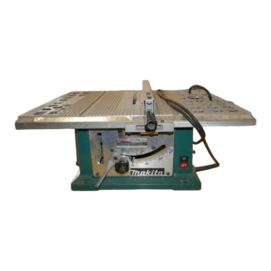
Table Saw
Arbor hole
210
mm
(8-114") MODEL 2708
Table size
Cutting capacities
Blade
diameter
9
0"
4 5"
(W
x
L)
INSTRUCTION MANUAL
SPEC I F ICATIONS
210"
64
mm
41
mm
660
mm
x
460
mm
5/8"
I
(8-1/4")
1
(2-1/2")
I
(1-5/8")
1
(26")
x ( 1
8-1/8")
N o load speed
I
Dimensions
( L
x
W x
H I
I
Net weight
1
17
kg
(37.5
Ibs)
1
460 m m
x
660
mm
x
375
mm
(1 8-1/8')
x
126")
x
(1 4-3/4")
4,500 R/min.
~~
Manufacturer reserves the right t o change specifications o f parts and accessories wlthout notice.
Note: Specifications o f parts and accessories may differ f r o m country t o country.
Advertisement
Table of Contents

Related Manuals for Makita 2708


Summary of Contents for Makita 2708
- Page 1 Table Saw (8-114") MODEL 2708 INSTRUCTION MANUAL SPEC I F ICATIONS Cutting capacities Blade Table size Arbor hole diameter 4 5" 0" 210" 5/8" (8-1/4") (2-1/2") (1-5/8") (26") 8-1/8") x ( 1 N o load speed Dimensions Net weight 460 m m 4,500 R/min.
- Page 2 BEFORE CONNECTING YOUR TOOL TO A POWER SOURCE Be sure you have read all GENERAL POWER TOOL SAFETY RULES GENERAL SAFETY PRECAUTIONS 1. KNOW YOUR POWER TOOL. Read the owner’s manual carefully. Learn the tools applications and limitations, as well as the specific potential hazards peculiar to it.
- Page 3 19. CHECK DAMAGED PARTS. Before further use of the tool, a guard or other that it will part that is damaged should be carefully checked ensure oper- ate properly and perform its intended function check for alignment of mov- ing parts, binding of moving parts, breakage of parts, mounting, and any other conditions that may affect its operation.
- Page 4 G RO U N DING IN STRUCTI ALL GROUNDED, CORD-CONNECTED TOOLS: the event of a malfunction or breakdown, grounding provides a path of least resistance for electric current t o reduce the risk of electric shock. This tool is equipped w i t h an electric cord hav- ing an equipment-grounding conductor and a grounding plug.
- Page 5 FOR TABLE SAW ADDITIONAL SAFETY RULES 1. ALWAYS use guard, spreader and anti-kickback fingers on all "thru-sawing" operations. Thru-sawing operations are those when the blade cuts complete- ly through the work piece as in ripping or cross cutting. ALWAYS hold the work firmly against the miter gage or fence. ALWAYS use a push stick for ripping narrow stock.
-
Page 6: Installing Saw Blade
ASSEMBLY PROCEDURE The tool is shipped from the factory with the saw blade and safety guide not in the instal- led condition. Assemble follows. CAUTION Always unplug the tool before assembly. INSTALLING SAW BLADE Remove the center cover on the table. Grip the outer flange with wrench 22;... -
Page 7: Installing Blade Guard
The spreader installing location is factory- adjusted. INSTALLING BLADE GUARD The antikick devicehpreader on the safety guide fits in between the safety guide in- stallation portion and the retainer plate be- hind the saw blade on the back side of the table. -
Page 8: Installation
INSTALLATION 9.62" 1244.3 mm) Secure the table saw so that will not move during operation. Bolt or screw the cabinet to bench (see 4 hole's in the base) or secure legs with screws. cm (1 2") clearance Leave more than between the table and a wall to allow chip 26"... - Page 9 FOR BEVEL CUTS Raise the lock lever for bevel cuts to release it, then swing the blade with the elevating knob until it reaches the desired angle from zero to 45 degrees. The bevel is indicated by the arrow pointer. After the desired angle setting i s reached, then lock the lock lever by pressing down firmly t o secure in place.
- Page 10 Bring the ruler underplate flush up against Hex bolt -attaching the rail inside, then fasten the hex bolt under d a t e attaching the underplate very securely. Ruler under date ZERO ADJUSTING FOR SETTING Bring the rip fence up flush against the side of the blade and loosen the screw.
-
Page 11: Cutting Operations
CUTTING OPERATIONS assure safe cutting operations, familiarize yourself thoroughly with the following safety rules and the cautions indicated a t the beginning. 1. switch on the saw only after making sure that nothing (wood, material, etc.) is con- tacting the saw blade. 2. - Page 12 Push Block Use a 3/4" piece of plywood. 1 2 ' Handle should be in center of plywood piece. Fasten with glue and wood screws as shown. 5/16" 2") of wood must always be glued to plywood Small piece (3/8" t o keep saw blade from dulling if operator cuts into push block by mistake.
- Page 13 Wood Auxiliary Facing (Miter Gauge) To prevent long board from wobbling, fit the miter gauge with an auxiliary fence board. Fasten with boltdnuts after drilling holes, but fasteners must not protrude from the face board, Featherboard The diagram shown illustrates dimensions for making a typical featherboard.
- Page 14 Use of Miter Gauge Slide the miter gauge into the thick grooves in the table. Loosen the knob on the gauge and align to desired angle (0 to 6 0 ' ) . Bring stock flush up against fence and feed gently forward into the blade.
- Page 15 Ripping Ripping i s the lengthwise cutting of a board. *When ripping stock over 6” wide: Feed the work forward with the hand on the rip fence side. Use the other hand t o hold the work in position against the rip fence.
- Page 16 Featherboards A "featherboard" or "fingerboard" is jig made from board cut off a t an angle of degrees. A series of parallel cuts made part way through the board. Board should be straight piece with no knots or cracks (see photo). Featherboards should be used for any operation in which workpiece i s not sawed all the way through (and the saw blade guard therefore removed.).
- Page 17 Keep the carbon brushes clean and free to slip in the holders. Both carbon brushes should be replaced same time. Use only Makita carbon brushes. Limit mark Lower saw blade as far as possible with the elevating knob; free lock lever and...
- Page 18 To maintain product SAFETY and RELIABILITY, repairs, any other maintenance or adjustment should be performed by Makita Authorized or Factory Service Centers, always using Makita replacement parts.
- Page 19 ACCESSORIES CAUTION These accessories or attachments are recommended for use w i t h your Makita tool specified in this manual. The use of any other accessories or attachments might present risk injury persons. accessories or attachments should used only in t h e proper and intended manner .TABLE SAW STAND...
- Page 20 .HOLDER SET COMPONENTS No. 191452-7) (Part Convenient to attach for holding large materials (either side and/or front and back). They are attached by clamps to the back of the table and secured with panhead screws. NOTE: Never attempt to move the table saw by gripping these holders.
- Page 21 w Chisel tooth combination saw blade For rip and cross-cut work. Most frequently used general carpentry. diy!2e, t f : k Diameter Part 518’’ 792281-7 (15,88mml 210-7 Warbide-tipped saw blade Fastest, smoothest, longer sawing without blade sharpening cuts wood, drywall, plastic, hardwood, etc.
- Page 22 Dado head (Part 191543-4) A dado is cutting a rabbet or a wide groove into the workpiece. The dado head set con- of two outside cutters, three inside sists 1/8" 1/16" 1/8" cutters and paper washers. Outside cutters : 6" diameter, 118" thick, 518"...
- Page 23 To install the dado head set, proceed as follows: Turn the tool off and unplug it before installing. Remove the blade guard with the spreader. Install the dado head with the teeth pointing down a t the front of the table. s e t Use the chart below to select the proper cutters to obtain the various cutting widths.
- Page 24 NOTE : When widths slightly greater than the above are required, fit the paper washers in between the inside and outside cutters to adjust the width. @Arrange the cutters that the tips of the inside cutters are positioned gullets of the outside cutter. When more than one inside cutter is used, space the tips of the inside cutters equidistantly in relation to one another.
- Page 25 CAUTION : .Only the Makita dado head set (Part No. 191543-4) should be used with Makita table 2708. saw Model .After dadoing, always replace the blade guard with the spreader back in original posi- i t s tion on the table saw.
- Page 26 26 --'I38 US 210 mm (8-1/4") TABLE SAW Model 2708...
- Page 27 Note: The switch, noise suppressor and other part configurations may differ from country to country.
- Page 28 Jan.-28'88 MODEL 2708 'LiM 'LiM DESCRIPTION DESCRIPTION MACHINE Sleeve Pan Head Screw M4xB Flat W a h r 9 Hex. Bolt M5x65 (With Washer1 Flat Washer 4 0 Ball Bearing 62OOLB Ball Bearing BZOICLB Motor Housing Splndle I " " . ,...
- Page 29 MAKITA LIMITED ONE YEAR WARRANTY Warranty Policy Every Makita tool is thoroughly inspected and tested before leaving the factory. It is warranted to be free of defects from workmanship and materials for the period of ONE YEAR from the date of original purchase.