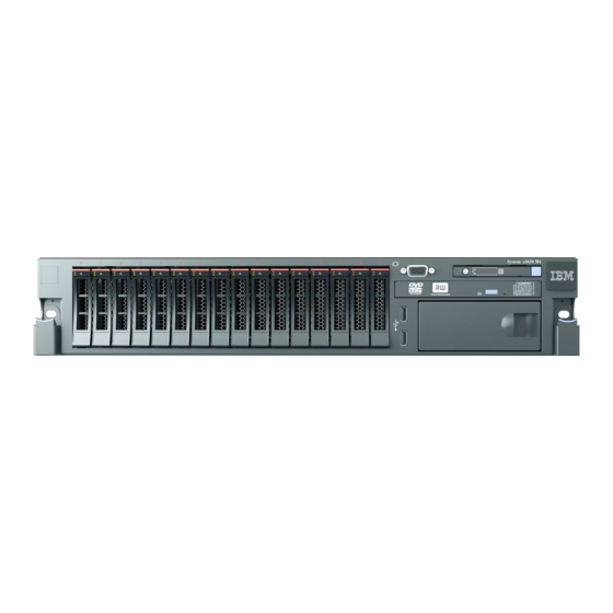
IBM System x3650 M4 Type 7915 Installation And User Manual
Type 7915
Hide thumbs
Also See for System x3650 M4 Type 7915:
- Problem determination and service manual (358 pages) ,
- Product manual (70 pages) ,
- Specifications (2 pages)
Table of Contents
Advertisement
Advertisement
Table of Contents

Related Manuals for IBM System x3650 M4 Type 7915


Summary of Contents for IBM System x3650 M4 Type 7915
- Page 1 System x3650 M4 Type 7915 Installation and User’s Guide...
- Page 3 System x3650 M4 Type 7915 Installation and User’s Guide...
- Page 4 Note: Before using this information and the product it supports, read the general information in Appendix B, “Notices,” on page 159, the IBM Safety Information and IBM Environmental Notices and User's Guide on the IBM System x Documentation CD, and the IBM Warranty Information document that comes with your server.
-
Page 5: Table Of Contents
Instructions for IBM Business Partners ....31 How to send DSA data to IBM ....31 Server components . - Page 6 IBM Advanced Settings Utility program....155 Updating IBM Systems Director ....155 The UpdateXpress System Pack Installer.
- Page 7 Hardware service and support ....158 IBM Taiwan product service ....158 Appendix B.
- Page 8 System x3650 M4 Type 7915: Installation and User’s Guide...
-
Page 9: Safety
Les sikkerhetsinformasjonen (Safety Information) før du installerer dette produktet. Antes de instalar este produto, leia as Informações sobre Segurança. Antes de instalar este producto, lea la información de seguridad. Läs säkerhetsinformationen innan du installerar den här produkten. © Copyright IBM Corp. 2012... - Page 10 Bu ürünü kurmadan önce güvenlik bilgilerini okuyun. viii System x3650 M4 Type 7915: Installation and User’s Guide...
- Page 11 Important: Each caution and danger statement in this document is labeled with a number. This number is used to cross reference an English-language caution or danger statement with translated versions of the caution or danger statement in the Safety Information document. For example, if a caution statement is labeled “Statement 1,”...
- Page 12 2. First, remove power cords from outlet. 3. Attach signal cables to connectors. 3. Remove signal cables from connectors. 4. Attach power cords to outlet. 4. Remove all cables from devices. 5. Turn device ON. System x3650 M4 Type 7915: Installation and User’s Guide...
- Page 13 Statement 2: CAUTION: When replacing the lithium battery, use only IBM Part Number 33F8354 or an equivalent type battery recommended by the manufacturer. If your system has a module containing a lithium battery, replace it only with the same module type made by the same manufacturer.
- Page 14 Laser radiation when open. Do not stare into the beam, do not view directly with optical instruments, and avoid direct exposure to the beam. Class 1 Laser Product Laser Klasse 1 Laser Klass 1 Luokan 1 Laserlaite Appareil A Laser de Classe 1 System x3650 M4 Type 7915: Installation and User’s Guide...
- Page 15 Statement 4: ≥ 18 kg (39.7 lb) ≥ 32 kg (70.5 lb) ≥ 55 kg (121.2 lb) CAUTION: Use safe practices when lifting. Statement 5: CAUTION: The power control button on the device and the power switch on the power supply do not turn off the electrical current supplied to the device.
- Page 16 Do not place any object on top of rack-mounted devices. This server is suitable for use on an IT power-distribution system whose maximum phase-to-phase voltage is 240 V under any distribution fault condition. Statement 27: System x3650 M4 Type 7915: Installation and User’s Guide...
- Page 17 CAUTION: Hazardous moving parts are nearby. Safety...
- Page 18 System x3650 M4 Type 7915: Installation and User’s Guide...
-
Page 19: Chapter 1. The System X3650 M4 Server
If firmware and documentation updates are available, you can download them from the IBM website. The server might have features that are not described in the documentation that comes with the server, and the documentation might be updated occasionally to include information about those features, or technical updates might be available to provide additional information that is not included in the server documentation. - Page 20 2.5-inch models are capable of expansion to sixteen 2.5-inch SAS hot-swap hard disk drive bays. System x3650 M4 Type 7915: Installation and User’s Guide...
- Page 21 The SAS ID for each bay is printed on the server front, above each bay. If firmware and documentation updates are available, you can download them from the IBM website. The server might have features that are not described in the Chapter 1. The System x3650 M4 server...
-
Page 22: The Ibm System X Documentation Cd
Note: The illustrations in this document might differ slightly from your hardware. ID label You can download an IBM ServerGuide Setup and Installation CD to help you configure the hardware, install device drivers, and install the operating system. For a list of supported optional devices for the server, see http://www.ibm.com/ servers/eserver/serverproven/compat/us/. -
Page 23: Using The Documentation Browser
This printed document contains information about the terms of the warranty. v Safety Information This document is in PDF on the IBM Documentation CD. It contains translated caution and danger statements. Each caution and danger statement that appears Chapter 1. The System x3650 M4 server... - Page 24 These updates are available from the IBM website. To check for updates, go to http://www.ibm.com/supportportal/. System x3650 M4 Type 7915: Installation and User’s Guide...
-
Page 25: Notices And Statements In This Document
Notices and statements in this document The caution and danger statements in this document are also in the multilingual Safety Information document, which is on the Documentation CD. Each statement is numbered for reference to the corresponding statement in your language in the Safety Information document. - Page 26 Weight: approximately 25 kg (55 lb) to 30 (full-height, full-length) x 2, kg (65 lb) depending upon configuration (full-height, half-length) x 1 – Two PCI-X (full-height, full-length) x 2, one PCI Express (full-height, half-length) System x3650 M4 Type 7915: Installation and User’s Guide...
- Page 27 Table 1. Features and specifications (continued) Electrical input with hot-swap ac power Environment: compliant with ASHRAE Environment: (continued) supplies: class A3 specifications. Server off: v Sine-wave input (50 - 60 Hz) required Server on: v Input voltage range automatically v Temperature: 5°C to 45°C (41°F to 113°F) selected v Temperature: v Relative humidity: 8% to 85%...
-
Page 28: What Your Server Offers
– Event logs for ServeRAID controllers and service processors The diagnostic programs create a merged log that includes events from all collected logs. The information is collected into a file that you can send to IBM System x3650 M4 Type 7915: Installation and User’s Guide... - Page 29 Determination and Service Guide on the IBM Documentation CD v Active Energy Manager The IBM Active Energy Manager solution is an IBM Systems Director plug-in that measures and reports server power consumption as it occurs. This enables you to monitor power consumption in correlation to specific software application programs and hardware configurations.
-
Page 30: Reliability, Availability, And Serviceability Features
Light path diagnostics provides LEDs to help you diagnose problems. For more information about the light path diagnostics, see “Operator information panel” on page 16 and the Problem Determination and Service Guide on the IBM System x Documentation CD. v PCI adapter capabilities The server has six PCI interface slots which can support PCI Express or PCI-X adapters through an optional PCI riser card. - Page 31 v Automatic restart on nonmaskable interrupt (NMI) v Automatic restart after a power failure v Backup basic input/output system switching under the control of the Integrated Management Module II (IMM2) v Built-in monitoring for fan, power, temperature, voltage, and power-supply redundancy v Cable-presence detection on most connectors v Chipkill memory protection...
-
Page 32: Ibm Systems Director
A set of common tasks that are included with IBM Systems Director provides many of the core capabilities that are required for basic management, which means instant out-of-the-box business value. -
Page 33: Server Controls, Leds, And Power
Server controls, LEDs, and power This section describes the controls and light-emitting diodes (LEDs) and how to turn the server on and off. Front view The following illustration shows the controls, LEDs, and connectors on the front of the 2.5-inch SAS/SATA hot-swap hard disk drive server model. Hard disk drive USB 2 USB 1... -
Page 34: Operator Information Panel
A system-locator LED is also on the rear of the server. This LED is used as a presence detection button as well. You can use IBM Systems Director or IMM2 web interface to light this LED remotely. This LED is controlled by the IMM2. -
Page 35: Light Path Diagnostics Panel
the light path diagnostics panel on the operator information panel or on the system board is also lit to help isolate the error. This LED is controlled by the IMM2. Light path diagnostics panel The light path diagnostics panel is located on the top of the operator information panel. - Page 36 Make sure that both LEDs are lit, the power supply power supplies installed in the server are of the same rating configuration is invalid. or wattage. System x3650 M4 Type 7915: Installation and User’s Guide...
- Page 37 Use the IBM Power Configurator utility to determine supplies are damaged. current system power consumption. For more information and to download the utility, go to http://www-03.ibm.com/systems/bladecenter/resources/...
- Page 38 5. If the CONFIG LED and the HDD LED are lit, check the system-error logs for information about the error. Replace any component that is identified in the error log. LINK Reserved. System x3650 M4 Type 7915: Installation and User’s Guide...
- Page 39 (Trained technician only) Replace the failing microprocessor (see “Installing a second microprocessor and heat sink” on page 101). c. For more information, go to http://www.ibm.com/ systems/support/supportsite.wss/ docdisplay?brandind=5000008&lndocid=SERV-CALL. 2. If the CONFIG LED and the CPU LED are lit, the system issues an invalid microprocessor configuration error.
- Page 40 Battery v (Trained technician only) System board 2. Check the system-error log for information about the error. 3. Replace the failing component: v Battery v (Trained technician only) System board System x3650 M4 Type 7915: Installation and User’s Guide...
-
Page 41: Rear View
1) Replace the hard disk drive. 2) Replace the hard disk drive backplane. e. If the problem remains, go to http://www.ibm.com/ systems/support/supportsite.wss/ docdisplay?brandind=5000008&lndocid=SERV-CALL. 2. If the HDD LED and the CONFIG LED are lit, complete the following steps to correct the problem: a. - Page 42 Ethernet LAN that is connected to the Ethernet port. Ethernet link LEDs: When these LEDs are lit, they indicate that there is an active link connection on the 10BASE-T, 100BASE-TX, or 1000BASE-TX interface for the Ethernet port. System x3650 M4 Type 7915: Installation and User’s Guide...
- Page 43 This LED is the same as the system-error LED on the front of the server. Locator LED: Use this LED to visually locate the server among other servers. You can use IBM Systems Director to light this LED remotely. This LED is the same as the system-locator LED on the front of the server.
- Page 44 4. If the problem remains, replace the power-supply. The power supply Replace the power supply. has failed. The power supply Replace the power supply. has failed. The power supply Replace the power supply. has failed. System x3650 M4 Type 7915: Installation and User’s Guide...
-
Page 45: Server Power Features
AC power-supply LEDs Error (!) Description Action Notes Power-supply not Typically indicates a 1. Reseat the power supply. fully seated, faulty power-supply is not 2. Follow actions in the “Power system board, or fully seated. problems” under the the power supply Troubleshooting tables in the has failed. -
Page 46: Turning Off The Server
2. Ethernet 1 connector supports Wake on LAN feature. 3. When you turn on the server with the graphical adapters installed, the IBM logo displays on the screen after approximately 3 minutes. This is normal operation while the system loads. - Page 47 Note: When you install any PCI adapter, the power cords must be disconnected from the power source before you remove the PCI Express riser-card assembly and the PCI-X riser-card assembly. Otherwise, the Wake on LAN feature might not work. v The integrated management module II (IMM2) can turn off the server as an automatic response to a critical system failure.
- Page 48 System x3650 M4 Type 7915: Installation and User’s Guide...
-
Page 49: Chapter 2. Installing Optional Devices
2. Shut down and restart the server multiple times to ensure that the server is correctly configured and functions correctly with the newly installed devices. 3. Save the DSA log as a file and send it to IBM. For information about transferring data and logs, see http://publib.boulder.ibm.com/infocenter/toolsctr/v1r0/ index.jsp?topic=/dsa/dsa_main.html. -
Page 50: Server Components
Battery holder Power supply filler panel Battery tray SAS hard disk drive backplane Power supply Tape drive DVD drive optional Operator information panel 4-drive filler panel Front bezel Tape drive filler panel System x3650 M4 Type 7915: Installation and User’s Guide... -
Page 51: System-Board Internal Connectors
System-board internal connectors The following illustration shows the internal connectors on the system board. PCI riser 10G Ethernet PCI riser NMI button connector 2 connector connector 1 Battery SAS 1 Video card power SAS 0 connector 1 USB hypenisor RAID upgrade connector connector Optial disk drive... -
Page 52: System-Board External Connectors
The following illustration shows the external input/output connectors on the system board. Ethernet 4 connector Ethernet 3 connector Dedicated Ethernet 2 systems- connector management Ethernet USB 3 - 6 Serial Video Ethernet 1 connector connectors connector connector connector System x3650 M4 Type 7915: Installation and User’s Guide... -
Page 53: System-Board Switches And Jumpers
System-board switches and jumpers The following illustration shows the location and description of the switches and jumpers. Note: If there is a clear protective sticker on the top of the switch blocks, you must remove and discard it to access the switches. The default positions for the UEFI and the IMM recovery jumpers are pins 1 and 2. - Page 54 42, and “Turning off the server” on page 28.) 2. Any system-board switch or jumper blocks that are not shown in the illustrations in this document are reserved. System x3650 M4 Type 7915: Installation and User’s Guide...
-
Page 55: System-Board Leds
System-board LEDs The following illustration shows the light-emitting diodes (LEDs) on the system board. Note: Error LEDs remain lit only while the server is connected to power. System Error Locator LED Power LED Enclosure management heartbeat LED Imm2 heartbeat Standby power 10G Ethernet card error LED Battery... -
Page 56: System-Board Optional Device Connectors
Optional PCI riser connector 1 Optional PCI riser connector 2 Optical drive connector USB tape connector Microprocessor 2 Microprocessor 1 DIMM 19-24 DIMM 1-6 Fan 4 DIMM 7-18 connector System x3650 M4 Type 7915: Installation and User’s Guide... -
Page 57: Pci Riser-Card Adapter Connectors
PCI riser-card adapter connectors The following illustration shows the connectors on the PCI riser card for user-installable PCI adapters. riser-card riser-card assembly assembly (in short position) (in long position) Adapter Adapter connectors connectors Adapter Adapter Full-length adapter Full-length bracket adapter bracket PCI riser-card assembly LEDs The following illustration shows the light-emitting diodes (LEDs) on the PCI... -
Page 58: Installation Guidelines
If the server is not working correctly, see the Problem Determination and Service Guide on the IBM System x Documentation CD for diagnostic information. v Observe good housekeeping in the area where you are working. Place removed covers and other parts in a safe place. -
Page 59: System Reliability Guidelines
When you are finished working on the server, reinstall all safety shields, guards, labels, and ground wires. v For a list of supported optional devices for the server, see http://www.ibm.com/ servers/eserver/serverproven/compat/us/. System reliability guidelines... -
Page 60: Handling Static-Sensitive Devices
Do not place the device on the server cover or on a metal surface. v Take additional care when handling devices during cold weather. Heating reduces indoor humidity and increases static electricity. System x3650 M4 Type 7915: Installation and User’s Guide... -
Page 61: Internal Cable Routing And Connectors
Internal cable routing and connectors The following illustration shows the internal routing and connectors for the cables. The following notes describe additional information you must consider when you install or remove the cables: v To remove the cables, slightly press the cables toward the chassis; then, pull to remove the cables from the connectors on the system board. - Page 62 Release tab Optical drive connector DVD drive cable Cable connector latch System x3650 M4 Type 7915: Installation and User’s Guide...
-
Page 63: Usb And Video Cable Connection
USB and video cable connection The following illustration shows the internal routing and connectors for the front USB and video cables. USB cable Video cable Chapter 2. Installing optional devices... -
Page 64: Operator Information Panel Cable Connection
Failing to install or remove the cable with care may damage the connectors on the system board. Any damage to the connectors may require replacing the system board. Operator panel cable System x3650 M4 Type 7915: Installation and User’s Guide... - Page 65 VGA cable connections The following illustration shows the internal routing and connectors for the video graphic adapter (VGA) cables. Video graphic adapters VGA power connector 2 VGA power cables VGA power connector 1 Chapter 2. Installing optional devices...
-
Page 66: 2.5-Inch Hard Disk Drive Cable Connection
Configuration cable connection: The following illustration shows the internal routing for the configuration cable. Configuration cable Power cable connection: The following illustration shows the internal routing for the hard disk drive power cable. SAS/SATA backplane power cable System x3650 M4 Type 7915: Installation and User’s Guide... - Page 67 Hard disk drive cable connection: The following illustration shows the internal routing and connectors for the two SAS signal cables. Notes: 1. To connect the SAS signal cables, make sure that you first connect the signal cable, and then the power cable and configuration cable. 2.
- Page 68 Configuration cable connection: The following illustration shows the internal routing for the configuration cable. Configuration cable Power cable connection: The following illustration shows the internal routing for the hard disk drive power cable. SAS/SATA backplane power cable System x3650 M4 Type 7915: Installation and User’s Guide...
- Page 69 Hard disk drive cable connection: The following illustration shows the internal routing and connectors for the two SAS signal cables. Port 8-15 Port 0-7 SAS signal cables Chapter 2. Installing optional devices...
-
Page 70: 3.5-Inch Hard Disk Drive Cable Connection
The following illustration shows the internal routing for the configuration cable. Configuration cable Power cable connection The following illustration shows the internal routing for the hard disk drive power cable. SAS/SATA backplane power cable System x3650 M4 Type 7915: Installation and User’s Guide... -
Page 71: Hard Disk Drive Cable Connection
Hard disk drive cable connection The following illustration shows the internal routing and connectors for the two SAS signal cables. Port 4-5 Port 0-3 Port 0-3 Port 4-5 SAS signal cables Chapter 2. Installing optional devices... -
Page 72: Removing The Cover
If you operate the server for extended periods of time (over 30 minutes) with the cover removed, the IMM turns off the server. System x3650 M4 Type 7915: Installation and User’s Guide... -
Page 73: Removing A Pci Riser-Card Assembly
Removing a PCI riser-card assembly The server comes with one riser-card assembly (with option to add one more) that each contains two to three PCI slots. See http://www.ibm.com/servers/eserver/ serverproven/compat/us/ for a list of riser-card assemblies that you can use with the server. -
Page 74: Installing A Pci Riser-Card Assembly
5. Press down on the assembly. Make sure that the riser-card assembly is fully seated in the riser-card connector on the system board. If you have other devices to install, do so now. Otherwise, go to “Completing the installation” on page 135. System x3650 M4 Type 7915: Installation and User’s Guide... -
Page 75: Removing The Air Baffle
Removing the air baffle When you work with some optional devices, you must first remove the air baffle to access certain components or connectors on the system board. The following illustration shows how to remove the air baffle. PCI riser-card assembly 2 PCI riser-card assembly 1... -
Page 76: Installing The Air Baffle
56. Attention: For proper cooling and airflow, replace the air baffle before you turn on the server. Operating the server with the air baffle removed might damage server components. System x3650 M4 Type 7915: Installation and User’s Guide... -
Page 77: Stretching A Pci Riser-Card Assembly
Stretching a PCI riser-card assembly Note: It is not necessary to capture adaptor card with the full-length adaptor bracket when installing half length adaptor cards. If you are installing a full-length adapter in the upper riser-card PCI slot, you must first stretch the PCI riser-card assembly. -
Page 78: Installing A Pci Adapter
See “System-board optional device connectors” on page 38 for the location of the internal SAS/SATA RAID connector and SAS/SATA RAID riser-card slots. You can install an optional IBM ServeRAID SAS/SATA adapter in the slot. For configuration information, see the ServeRAID documentation at http://www.ibm.com/systems/support/,... - Page 79 riser-card riser-card assembly assembly (in short position) (in long position) Adapter Adapter connectors connectors Adapter Adapter Full-length adapter Full-length bracket adapter bracket To install a PCI adapter, complete the following steps: 1. Read the safety information that begins on page vii and “Installation guidelines” on page 40.
- Page 80 PCI riser-card assembly. v Make sure that cables are not pinched by the server components. 10. Align the PCI riser-card assembly with the selected PCI riser-card connector on the system board. System x3650 M4 Type 7915: Installation and User’s Guide...
- Page 81 PCI riser-card assembly 2 PCI riser-card assembly 1 v PCI riser-card connector 1: Carefully fit the two alignment slots on the side of the assembly onto the two alignment brackets in the side of the chassis; align the rear of the assembly with the guides on the rear of the server. v PCI riser-card connector 2: Carefully align the bottom edge (the contact edge) of the riser-card assembly with the PCI riser-card connector on the system board;...
-
Page 82: Removing A Pci Adapter
3. Press down on the left and right side rack latches and slide the server out of the rack enclosure until both slide rails lock; then, remove the cover (see “Removing the cover” on page 54). System x3650 M4 Type 7915: Installation and User’s Guide... -
Page 83: Installing A Hard Disk Drive
Important: Do not install a SCSI hard disk drive in this server. v Make sure that the devices that you are installing are supported. For a list of supported optional devices for the server, see http://www.ibm.com/systems/info/ x86servers/serverproven/compat/us/. v Make sure that you have all the cables and other equipment that are specified in the documentation that comes with the drive. - Page 84 LED flashes slowly and the green activity LED remains lit during the rebuild process. If the yellow LED remains lit, see the Problem Determination and Service Guide on the IBM Documentation CD for hard disk drive problem solutions.
-
Page 85: Removing A Hard Disk Drive
Installing a SAS/SATA 8 Pac HDD option If the server is a 16-drive-capable model with eight hard disk drive bays installed, you can install an IBM System x3650 M4 Hot-swap SAS/SATA 8 Pac HDD option. See http://www.ibm.com/servers/eserver/serverproven/compat/us/ for a list of supported optional devices. - Page 86 7. Disconnect the SAS signal cables from the system board. Leave the other end of the SAS signal cables connected to the hard disk drive backplanes. 8. Remove hard disk drive backplane 1 from the server. System x3650 M4 Type 7915: Installation and User’s Guide...
- Page 87 Hard disk drive backplane signal cable Configuration cable Power cable a. From backplane 1, disconnect the following cables in the order listed: v Power cable 1 v SAS signal cable 2 v Configuration cable 3 b. Lift backplane 1 out of the server by pulling it toward the rear of the server and then lifting it up.
- Page 88 10. Connect the loose end of the SAS signal cables to the system board. Route the cable underneath the cable retention features on the baffle. See the System x3650 M4 Type 7915: Installation and User’s Guide...
- Page 89 illustration. SAS 1 SAS 0 SAS signal cables 11. Make sure that the configuration cable is connected to the backplanes and system board. Chapter 2. Installing optional devices...
- Page 90 Configuration cable 12. Make sure that the SAS power cable is connected to the backplanes and system board. System x3650 M4 Type 7915: Installation and User’s Guide...
-
Page 91: Installing A Sas/Sata 8 Pac Hdd With A Serveraid Adapter Option
Installing a SAS/SATA 8 Pac HDD with a ServeRAID adapter option If the server is a 16-drive-capable model with eight hard disk drive bays installed, you can install an IBM System x3650 M4 Hot-swap SAS/SATA 8 Pac HDD with a ServeRAID adapter option. See http://www.ibm.com/servers/eserver/serverproven/ compat/us/ for a list of supported optional devices. - Page 92 4-drive filler panel 5. To obtain more working room, remove fans 2 and 3 (see “Removing a dual-motor hot-swap fan” on page 123). 6. Install the new backplane in slot 2: System x3650 M4 Type 7915: Installation and User’s Guide...
- Page 93 Hard disk drive backplane signal cable Configuration cable Power cable a. Connect the following cables in the order listed: v Configuration cable 1 v SAS signal cable 2 v Power cable 3 b. Angle the new backplane and place the bottom edge into the slots for backplane 2 on the chassis next to the optical drive.
- Page 94 PCI riser-card assembly” on page 56). PCI riser-card assembly Bracket Expansion-slot cover Adapter 12. Route the cables underneath the cable retention (taking the RAID adapter, part number 46M0912, as an example). System x3650 M4 Type 7915: Installation and User’s Guide...
- Page 95 Adapter Port 8-11 Port 12-15 SAS signal cables 13. Make sure that the configuration cable is connected to the backplanes and system board. Chapter 2. Installing optional devices...
- Page 96 Configuration cable 14. Make sure that the SAS power cable is connected to the backplanes and system board. System x3650 M4 Type 7915: Installation and User’s Guide...
-
Page 97: Installing A Sas/Sata 8 Pac Hdd With 2 6 Gb Performance Optimized Hba Adapters Option
HBA adapters option If the server is a 16-drive-capable model with eight hard disk drive bays installed, you can install an IBM System x3650 M4 Hot-swap SAS/SATA 8 Pac HDD with 2 6 GB performance optimized HBA adapters option. See http://www.ibm.com/servers/ eserver/serverproven/compat/us/ for a list of supported optional devices. - Page 98 5. To obtain more working room, remove fans 2 and 3 (see “Removing a dual-motor hot-swap fan” on page 123). 6. Remove the 2 SAS cables which connect both the backplane and the system board. System x3650 M4 Type 7915: Installation and User’s Guide...
- Page 99 Port 4-7 Port 0-3 Port 0-3 Port 4-7 SAS signal cables 7. Take out the 2 SAS cables (925 mm) from the SAS cable option and connect them to the backplane. Chapter 2. Installing optional devices...
- Page 100 Connect another SAS signal cable to the other SAS connector for drive bays 4-7. Connector for Connector for drive bays 0-3 drive bays 4-7 signal cable signal cable RAID adapter System x3650 M4 Type 7915: Installation and User’s Guide...
- Page 101 12. Align and install the PCI riser-card assembly in the server (see “Installing a PCI riser-card assembly” on page 56). PCI riser-card assembly Bracket Expansion-slot cover Adapter 13. Route the cables underneath the cable retention. Adapter Port 0-3 Port 4-7 SAS signal cables 14.
-
Page 102: Installing 2 X 8 1.8-Inch Ssds With 2 6 Gb Performance Optimized Hba Adapters Option
Two eXFlash 1.8-inch drive cage and backplane assemblies v Two RAID adapters (part number 46M0912) Note: RAID adapters come in a different option kits. Touch the static-protective packages to any unpainted metal surface on the server. System x3650 M4 Type 7915: Installation and User’s Guide... - Page 103 To install the 2 x 8 1.8-inch SSDs with 2 6 GB performance optimized HBA adapters option in the server, complete the following steps. 1. Read the safety information that begins on page vii and “Installation guidelines” on page 40. 2.
- Page 104 Connect a SAS signal cable that comes with the option kit to the RAID adapter connector for drive bays 8-11. b. Connect another SAS signal cable to the other SAS connector for drive bays 12-15. System x3650 M4 Type 7915: Installation and User’s Guide...
- Page 105 Connector for Connector for Connector for Connector for drive bays 8-11 drive bays 12-15 drive bays 16-19 drive bays 20-23 signal cable signal cable signal cable signal cable RAID adapter RAID adapter c. Connect a SAS signal cable that comes with the option kit to the RAID adapter connector for drive bays 16-19.
- Page 106 Adapter Port 8-11 Port 12-15 SAS signal cables System x3650 M4 Type 7915: Installation and User’s Guide...
- Page 107 Adapter Port 16-19 Port 20-23 SAS signal cables 14. Make sure that the configuration cable is connected to the backplanes and system board. Chapter 2. Installing optional devices...
- Page 108 0-7 and 8-15) bays 16-23) Note: Leave the cable segment with the label 3 unconnected. 15. Make sure that the SAS power cable is connected to the backplanes and system board. System x3650 M4 Type 7915: Installation and User’s Guide...
-
Page 109: Installing 4 X 8 1.8-Inch Ssds With 2 6 Gb Performance Optimized Hba Adapters Option
To order 4 x 8 1.8-inch SSDs with 2 6 GB performance optimized HBA adapters option, contact your IBM marketing representative or authorized reseller. The 4 x 8 1.8-inch SSDs with 2 6 GB performance optimized HBA adapters option... - Page 110 6. Install the new backplane assemblies. eXFlash 1.8-inch drive cage and backplane assembly 7. Connect the following cables in the order listed: v Configuration cable 1 v SAS signal cables 2 v Power cable 3 System x3650 M4 Type 7915: Installation and User’s Guide...
- Page 111 SAS signal cables eXFlash 1.8-inch drive cage and backplane assembly Configuration cable Power cable 8. Touch the static-protective package that contains the RAID adapter to any unpainted metal surface on the server. Then, remove the RAID adapter from the package. 9.
- Page 112 12. Align and install the PCI riser-card assembly 2 in the server (see “Installing a PCI riser-card assembly” on page 56). PCI riser-card assembly Bracket Expansion-slot cover Adapter 13. Route the cables underneath the cable retention. System x3650 M4 Type 7915: Installation and User’s Guide...
- Page 113 Adapter Port 16-19 Port 20-23 SAS signal cables Chapter 2. Installing optional devices...
- Page 114 Adapter Port 24-27 Port 28-31 SAS signal cables 14. Make sure that the configuration cable is connected to the backplanes and system board. System x3650 M4 Type 7915: Installation and User’s Guide...
- Page 115 SAS/SATA backplane config connector 2 Configuration cable (Connector for drive bays 16-31) 15. Make sure that the SAS power cable is connected to the backplanes and system board. Chapter 2. Installing optional devices...
-
Page 116: Installing An Optional Tape Drive
The IBM System x3650 M4 RDX-DDS internal enablement kit is used to install an IBM tape drive in an IBM System x3650 M4 server. The IBM System x3650 M4 RDX-DDS internal enablement kit is compatible only with the following tape drives:... - Page 117 To install a SATA or USB tape drive, complete the following steps: 1. Read the safety information that begins on page vii, “Installation guidelines” on page 40, and “Handling static-sensitive devices” on page 42. 2. Turn off the server and peripheral devices, and disconnect the power cords and all external cables.
- Page 118 8. Slide the tape-drive assembly the rest of the way into the tape-drive bay. 9. Push the latch to the closed (locked) position. If you have other devices to install or remove, do so now. Otherwise, go to “Completing the installation” on page 135. System x3650 M4 Type 7915: Installation and User’s Guide...
-
Page 119: Installing A Second Microprocessor And Heat Sink
Note: Removing the heat sink from the microprocessor destroys the even distribution of the thermal grease and requires replacing the thermal grease. v To order an additional optional microprocessor, contact your IBM marketing representative or authorized reseller. Chapter 2. Installing optional devices... - Page 120 Open the microprocessor retainer. Attention: Do not touch the connectors on the microprocessor and the microprocessor socket. Microprocessor release lever Socket cover Microprocessor release lever 8. Install the microprocessor on the microprocessor socket: System x3650 M4 Type 7915: Installation and User’s Guide...
- Page 121 a. Touch the static-protective package that contains the new microprocessor to any unpainted on the chassis or any unpainted metal surface on any other grounded rack component; then, carefully remove the microprocessor from the package. b. Release the sides of the cover and remove the cover from the installation tool.
- Page 122 Close the microprocessor retainer on the microprocessor socket. b. Identify which release lever is labeled as the first release lever to close and close it. c. Close the second release lever on the microprocessor socket. System x3650 M4 Type 7915: Installation and User’s Guide...
- Page 123 Microprocessor release lever Microprocessor Microprocessor release lever 11. Install the heat sink: Attention: v Do not set down the heat sink after you remove the plastic cover. v Do not touch the thermal grease on the bottom of the heat sink after you remove the plastic cover.
-
Page 124: Thermal Grease
4. Use a clean area of the cleaning pad to wipe the thermal grease from the microprocessor; then, dispose of the cleaning pad after all of the thermal grease is removed. System x3650 M4 Type 7915: Installation and User’s Guide... -
Page 125: Installing A Memory Module
(SDRAM) dual inline memory modules (DIMMs) with error correcting code (ECC). See http://www.ibm.com/servers/eserver/serverproven/compat/us/ for a list of supported memory modules for the server. – The specifications of a DDR3 DIMM are on a label on the DIMM, in the following format. - Page 126 1333 MHz when the following conditions is met: – Two 1.35 V single-rank, dual-ranl, or quad-rank UDIMMs, RDIMMs or LRDIMMs are installed in the same channel. In the Setup utility, Memory System x3650 M4 Type 7915: Installation and User’s Guide...
- Page 127 speed is set to Max performance and LV-DIMM power is set to Enhance performance mode. The 1.35 V UDIMMs, RDIMMs or LRDIMMs will function at 1.5 V. v The server supports a maximum of 16 dual-rank UDIMMs. The server supports up to two UDIMMs per channel.
-
Page 128: Dimm Installation Sequence
1, 4, 9, 12, 2, 5, 8, 11, 3, 6, 7, 10 installed Two microprocessors 1, 13, 4, 16, 9, 21, 12, 24, 2, 14, 5, 17, 8, 20, 11, 23, 3, 15, installed 6, 18, 7, 19, 10, 22 System x3650 M4 Type 7915: Installation and User’s Guide... -
Page 129: Memory Mirrored Channel
Memory mirrored channel Memory mirrored channel mode replicates and stores data on two pairs of DIMMs within two channels simultaneously. If a failure occurs, the memory controller switches from the primary pair of memory DIMMs to the backup pair of DIMMs. To enable memory mirrored channel through the Setup utility, select System Settings →... -
Page 130: Memory Rank Sparing
Twelfth pair of DIMMs 15, 18 Note: DIMM connectors 3, 6, 7, 10, 15, 18, 19, and 22 are not used in memory rank sparing mode when UDIMMs are installed in the server. System x3650 M4 Type 7915: Installation and User’s Guide... -
Page 131: Installing A Dimm
Installing a DIMM To install a DIMM, complete the following steps. 1. Read the safety information that begins on page vii and “Installation guidelines” on page 40. 2. Turn off the server and peripheral devices, and disconnect the power cord and all external cables (see “Turning off the server”... - Page 132 If you have other devices to install or remove, do so now. Otherwise, go to “Completing the installation” on page 135. Go to the Setup utility and make sure all the installed DIMMs are present and enabled. System x3650 M4 Type 7915: Installation and User’s Guide...
-
Page 133: Installing A Hot-Swap Ac Power Supply
Before you install an additional power supply or replace a power supply with one of a different wattage, you may use the IBM Power Configurator utility to determine current system power consumption. For more information and to download the utility, go to http://www-03.ibm.com/systems/bladecenter/resources/ powerconfig.html. - Page 134 3. If you are adding a power supply to the server, attach the redundant power information label that comes with this option on the server cover near the power supplies. System x3650 M4 Type 7915: Installation and User’s Guide...
- Page 135 Made in China xxx-xxx/xxx-xxx x,x/x,x xx/xx Hz Manufacturer IBM Corporation Copyright Code and Parts Contained Herein. ©Copyright IBM Corp 2010 All Rights Reserved XXXX Canada ICES NMB 003 Class Classe A KCC REM IBC 7915 Chapter 2. Installing optional devices...
-
Page 136: Installing A Hot-Swap Dc Power Supply
10. (IBM Business Partners only) Restart the server. Confirm that it starts correctly and recognizes the newly installed devices, and make sure that no error LEDs are lit. 11. (IBM Business Partners only) Complete the additional steps in “Instructions for IBM Business Partners”... - Page 137 This equipment is designed to permit the connection of the earthed conductor of the dc supply circuit to the earthing conductor at the equipment. If this connection is made, all of the following conditions must be met: v This equipment shall be connected directly to the dc supply system earthing electrode conductor or to a bonding jumper from an earthing terminal bar or bus to which the dc supply system earthing electrode conductor is connected.
- Page 138 The product also might have more than one power cord. To remove all electrical current from the product, make sure that all power cords are disconnected from the power source. System x3650 M4 Type 7915: Installation and User’s Guide...
- Page 139 Statement 34: CAUTION: To reduce the risk of electric shock or energy hazards: v This equipment must be installed by trained service personnel in a restricted-access location, as defined by the NEC and IEC 60950-1, First Edition, The Standard for Safety of Information Technology Equipment. v Connect the equipment to a properly grounded safety extra low voltage (SELV) source.
- Page 140 -48 volt dc power supply, and make the connections to and disconnections from the -48 volt dc power source. IBM service technicians are not certified or authorized to install or remove the -48 volt power cable.
-
Page 141: Removing A Dual-Motor Hot-Swap Fan
7. Route the power cord through the handle and cable tie if any, so that it does not accidentally become unplugged. 8. Connect the other ends of the dc power cable to the dc power source. Cut the wires to the correct length, but do not cut them shorter than 150 mm (6 inch). If the power source requires ring terminals, you must use a crimping tool to install the ring terminals to the power cord wires. -
Page 142: Installing A Dual-Motor Hot-Swap Fan
Attention: To ensure proper server operation, if a fan fails, replace it within 30 seconds. Have a replacement fan ready to install as soon as you remove the failed fan. System x3650 M4 Type 7915: Installation and User’s Guide... -
Page 143: Installing An Optional Serveraid Upgrade Adapter
Vertical tabs Fan 4 Fan 3 Fan 2 Fan 1 To install any of the four replaceable fans, complete the following steps: 1. Read the safety information that begins on page vii and “Installation guidelines” on page 40. 2. If you have not done so already, slide the server out of the rack and remove the cover (see “Removing the cover”... - Page 144 SAS controller battery on the remote battery tray” on page 127). If you have other devices to install or remove, do so now. Otherwise, go to “Completing the installation” on page 135. System x3650 M4 Type 7915: Installation and User’s Guide...
-
Page 145: Installing A Serveraid Sas Controller Battery On The Remote Battery Tray
Installing a ServeRAID SAS controller battery on the remote battery tray Note: For brevity, in this documentation the Intelligent Battery Backup Unit (iBBU) is often referred to as the battery. When you install any ServeRAID SAS controller that comes with batteries, it is sometimes necessary to install the batteries in another location in the server to prevent the batteries from overheating. -
Page 146: Installing A Usb Hypervisor Memory Key
USB hypervisor memory key, with embedded hypervisor software. To install the USB hypervisor memory key, complete the following steps: 1. Read the safety information that begins on page vii and “Installation guidelines” on page 40. System x3650 M4 Type 7915: Installation and User’s Guide... - Page 147 2. Turn off the server and peripheral devices and disconnect all power cords and external cables (see “Turning off the server” on page 28). 3. Remove the cover (see “Removing the cover” on page 54). 4. Remove PCI riser-card assembly (see “Removing a PCI riser-card assembly” on page 55).
-
Page 148: Removing A Usb Hypervisor Memory Key
“Completing the installation” on page 135. Note: You must configure the server not to look for the hypervisor USB drive. See Chapter 3, “Configuring the server,” on page 141 for information about disabling hypervisor support. System x3650 M4 Type 7915: Installation and User’s Guide... -
Page 149: Installing The Optional Dual-Port Network Adapter
– NIC – iSCSI (enabled after FoD installed) – FCoE (enabled after FoD installed) v To download the latest version of drivers for iSCSI and FCoE from the IBM website, complete the following steps: 1. Go to http://www.ibm.com/support/fixcentral/. 2. From the Product support, select System x. - Page 150 – NIC – iSCSI (enabled after FoD installed) – FCoE (enabled after FoD installed) v To download the latest version of drivers for iSCSI and FCoE from the IBM website, complete the following steps: 1. Go to http://www.ibm.com/support/fixcentral/. 2. From the Product support, select System x.
- Page 151 – Emulex iSCSI Device Driver for Windows 2008 – Emulex FCoE Device Driver for Windows 2008 Note: Changes are made periodically to the IBM website. The actual procedure might vary slightly from what is described in this document. v Port 0 on the Emulex dual port 10GbE SFP+ Embedded VFA III adapter can be configured as shared system management.
- Page 152 (see “Installing a PCI riser-card assembly” on page 56). If you have other devices to install or remove, do so now. Otherwise, go to “Completing the installation” on page 135. System x3650 M4 Type 7915: Installation and User’s Guide...
-
Page 153: Installing An Optional Dvd Drive
Installing an optional DVD drive For a list of supported optional optical disk drives for the server, see http://www.ibm.com/servers/eserver/serverproven/compat/us/. To install an optional DVD drive, complete the following steps. Drive retention clip Alignment pins 1. Read the safety information that begins on page vii and “Installation guidelines”... - Page 154 4. Install the server in a rack. See the Rack Installation Instructions that come with the server for complete rack installation and removal instructions. 5. To attach peripheral devices and connect the power cords, see “Connecting the external cables” on page 138. System x3650 M4 Type 7915: Installation and User’s Guide...
-
Page 155: Replacing The Server Cover
Replacing the server cover To replace the server cover, complete the following steps: 1. Make sure that all cables, adapters, and other components are installed and seated correctly and that you have not left loose tools or parts inside the server. Also, make sure that all internal cables are correctly routed. -
Page 156: Connecting The External Cables
It might be easier for you to route cables before you connect the devices to the server. If the server comes with an installed operating system, see the documentation that comes with the operating system for additional cabling instructions. System x3650 M4 Type 7915: Installation and User’s Guide... -
Page 157: Updating The Server Configuration
Updating the server configuration When you start the server for the first time after you add or remove an internal device, external SAS device, or USB keyboard or mouse, you might receive a message that the configuration has changed. After the POST fails three times, the Setup utility starts automatically so that you can save the new configuration settings. - Page 158 System x3650 M4 Type 7915: Installation and User’s Guide...
-
Page 159: Chapter 3. Configuring The Server
However, you will still be able to access the web interface without the Integrated Management Module Advanced Upgrade. You can order the optional IBM Integrated Management Module Advanced Upgrade, if one did not come with your server. -
Page 160: Using The Serverguide Setup And Installation Cd
Use the ASU program online or out of band to modify UEFI settings from the command line without the need to restart the server to access the Setup utility. For more information about using this program, see “IBM Advanced Settings Utility program” on page 155. -
Page 161: Serverguide Features
CD, go to http://www.ibm.com/support/entry/portal/ docdisplay?lndocid=SERV-GUIDE and click IBM Service and Support Site. Note: Changes are made periodically to the IBM website. The actual procedure might vary slightly from what is described in this document. To start the ServerGuide Setup and Installation CD, complete the following steps: 1. -
Page 162: Setup And Configuration Overview
When you use the ServerGuide Setup and Installation CD, you do not need setup diskettes. You can use the CD to configure any supported IBM server model. The setup program provides a list of tasks that are required to set up your server model. -
Page 163: Using The Setup Utility
6. From the Operating system menu, select your operating system, and then click Search to display the available installation documents. Using the Setup utility Use the Unified Extensible Firmware Interface (UEFI), formerly BIOS, Setup Utility program to perform the following tasks: v View configuration information v View and change assignments for devices and I/O ports v Set the date and time... - Page 164 Select this choice to view or reset IMM2 to the default settings. - Reset IMM Select this choice to reset IMM2. – System Security Select this choice to view or configure Trusted Platform Module (TPM) support. – Adapters and UEFI Drivers System x3650 M4 Type 7915: Installation and User’s Guide...
- Page 165 Run the diagnostic programs to get more information about error codes that occur. See the Problem Determination and Service Guide on the IBM System x Documentation CD for instructions for running the diagnostic programs. Important: If the system-error LED on the front of the server is lit but there are no other error indications, clear the IMM2 system-event log.
-
Page 166: Passwords
If a power-on password is set, when you turn on the server, you must type the power-on password to complete the system startup. You can use any combination of 6 - 20 printable ASCII characters for the password. System x3650 M4 Type 7915: Installation and User’s Guide... -
Page 167: Administrator Password
Start the Setup utility and reset the power-on password. v Remove the battery from the server and then reinstall it. See the Problem Determination and Service Guide on the IBM System x Documentation CD for instructions for removing the battery. -
Page 168: Using The Boot Manager Program
You must use the service processor upgrade option to upgrade to IMM2 standard firmware and then use the remote presence upgrade option to upgrade to IMM2 premium firmware. System x3650 M4 Type 7915: Installation and User’s Guide... - Page 169 For more information about the IMM2, see the Integrated Management Module II User's Guide at http://www-947.ibm.com/support/entry/portal/ docdisplay?brand=5000008&lndocid=MIGR-5086346. The IMM2 supports the following basic systems-management features: v Environmental monitor with fan speed control for temperature, voltages, fan failure, and power supply failure.
-
Page 170: Obtaining The Ip Address For The Imm2
Using the remote presence capability and blue-screen capture The remote presence and blue-screen capture features are integrated functions of the Integrated Management Module II (IMM2). When the optional IBM Integrated Management Module Advanced Upgrade is installed in the server, it activates the remote presence functions. -
Page 171: Using The Embedded Hypervisor
For more information on Features on Demand (FoD), including instructions for automating the activation and installation of the activation key by using IBM ToolsCenter or IBM Director, see the IBM System x Features on Demand User’s Guide at http://www.ibm.com/systems/x/fod/ under the Help section. -
Page 172: Configuring The Ethernet Controller
Channel over Ethernet (FCoE) and iSCSI storage protocols that is integrated in the integrated management module. For more information and instructions for activating the Features on Demand Ethernet software key, see the IBM Features on Demand User’s Guide. To download the document, go to http://www.ibm.com/systems/x/fod/, log in, and click Help. -
Page 173: Configuring Raid Arrays
Updating IBM Systems Director If you plan to use IBM Systems Director to manage the server, you must check for the latest applicable IBM Systems Director updates and interim fixes. Note: Changes are made periodically to the IBM website. The actual procedure might vary slightly from what is described in this document. -
Page 174: The Updatexpress System Pack Installer
Go to http://www.ibm.com/systems/software/director/downloads/index.html. b. If a newer version of IBM Systems Director than what comes with the server is shown in the drop-down list, follow the instructions on the web page to download the latest version. 2. Install the IBM Systems Director program. -
Page 175: Appendix A. Getting Help And Technical Assistance
If you need help, service, or technical assistance or just want more information about IBM products, you will find a wide variety of sources available from IBM to assist you. This section contains information about where to go for additional information about IBM and IBM products, what to do if you experience a problem with your system, and whom to call for service, if it is necessary. -
Page 176: Software Service And Support
You can find service information for IBM systems and optional devices at http://www.ibm.com/systems/support/. Software service and support Through IBM Support Line, you can get telephone assistance, for a fee, with usage, configuration, and software problems with System x and xSeries servers, BladeCenter products, IntelliStation workstations, and appliances. For information about which products are supported by Support Line in your country or region, see http://www.ibm.com/services/sl/products/. -
Page 177: Appendix B. Notices
Web sites. The materials at those Web sites are not part of the materials for this IBM product, and use of those Web sites is at your own risk. IBM may use or distribute any of the information you supply in any way it believes appropriate without incurring any obligation to you. -
Page 178: Important Notes
IBM. Maximum memory might require replacement of the standard memory with an optional memory module. IBM makes no representation or warranties regarding non-IBM products and ® services that are ServerProven , including but not limited to the implied warranties of merchantability and fitness for a particular purpose. -
Page 179: Particulate Contamination
IBM makes no representations or warranties with respect to non-IBM products. Support (if any) for the non-IBM products is provided by the third party, not IBM. Some software might differ from its retail version (if available) and might not include user manuals or all program functionality. -
Page 180: Electronic Emission Notices
In the request, be sure to include the publication part number and title. When you send information to IBM, you grant IBM a nonexclusive right to use or distribute the information in any way it believes appropriate without incurring any obligation to you. -
Page 181: European Union Emc Directive Conformance Statement
EU-Mitgliedsstaaten und hält die Grenzwerte der EN 55022 Klasse A ein. Um dieses sicherzustellen, sind die Geräte wie in den Handbüchern beschrieben zu installieren und zu betreiben. Des Weiteren dürfen auch nur von der IBM empfohlene Kabel angeschlossen werden. IBM übernimmt keine Verantwortung für die Einhaltung der Schutzanforderungen, wenn das Produkt ohne Zustimmung der IBM verändert bzw. -
Page 182: Japan Vcci Class A Statement
Japan Electronics and Information Technology Industries Association (JEITA) statement Japanese Electronics and Information Technology Industries Association (JEITA) Confirmed Harmonics Guideline (products less than or equal to 20 A per phase) Korea Communications Commission (KCC) statement System x3650 M4 Type 7915: Installation and User’s Guide... -
Page 183: Russia Electromagnetic Interference (Emi) Class A Statement
Please note that this equipment has obtained EMC registration for commercial use. In the event that it has been mistakenly sold or purchased, please exchange it for equipment certified for home use. Russia Electromagnetic Interference (EMI) Class A statement People's Republic of China Class A electronic emission statement Taiwan Class A compliance statement Appendix B. - Page 184 System x3650 M4 Type 7915: Installation and User’s Guide...
-
Page 185: Index
110 cabling 99 DIMM installation sequence external routing 138 memory mirroring 111 system-board external connectors 34 non-mirroring mode 110 system-board internal connectors 33 rank sparing 112 caution statements 7 DIMMs installing 113 © Copyright IBM Corp. 2012... - Page 186 58 filler panel DIMM 113 4-drive 68 dual-port network adapter 131 hard-disk drive bay 66 DVD drive 135 finding hard disk drive 65 updated documentation 6 heat sink 101, 105 System x3650 M4 Type 7915: Installation and User’s Guide...
- Page 187 installing (continued) light path diagnostics (continued) hot-swap ac power supply 115 LEDs 18 hot-swap dc power supply 118 light path diagnostics LEDs 18 hypervisor flash device 128 light path diagnostics panel memory module 113 controls and LEDs 17 microprocessor 101, 102 Linux license agreement 6 PCI adapter 60 local area network (LAN) 11...
- Page 188 36 installing 56 switch block, system board 36 LEDs 39 symmetric multiprocessing 10 location 65 system removing 55, 56 error LED, front 16 locator LED, front 16 System x3650 M4 Type 7915: Installation and User’s Guide...
- Page 189 108 United States electronic emission Class A notice 162 United States FCC Class A notice 162 UpdateXpress 14, 156 updating IBM Systems Director 155 server configuration 139 Systems Director, IBM 155 USB connector 16, 24 using boot manager program 150...
- Page 190 System x3650 M4 Type 7915: Installation and User’s Guide...
- Page 192 Part Number: 00V9884 Printed in USA (1P) P/N: 00V9884...