Table of Contents
Advertisement
Your new drill press has been engineered and manufactured to our high standards for dependability, ease of operation, and
operator safety. When properly cared for, it will give you years of rugged, trouble-free performance.
WARNING:
To reduce the risk of injury, the user must read and understand the operator's manual before using this product.
Thank you for buying a RIDGID product.
SAVE THIS MANUAL FOR FUTURE REFERENCE
OPERATOR'S MANUAL
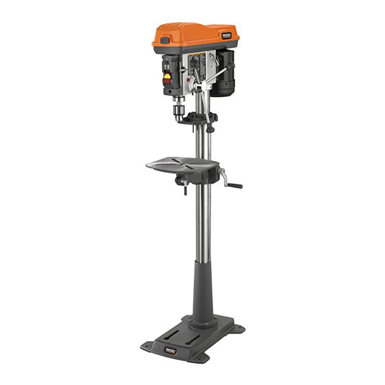
15 in. DRILL PRESS
DP15501
Advertisement
Table of Contents

Related Manuals for RIDGID DP15501


Summary of Contents for RIDGID DP15501
- Page 1 When properly cared for, it will give you years of rugged, trouble-free performance. WARNING: To reduce the risk of injury, the user must read and understand the operator’s manual before using this product. Thank you for buying a RIDGID product. SAVE THIS MANUAL FOR FUTURE REFERENCE...
-
Page 2: Table Of Contents
TABLE OF CONTENTS n Introduction ..................................2 n General Safety Rules ................................ 3 n Specific Safety Rules................................ 4 n Symbols..................................5-6 n Electrical ................................... 7 n Glossary of Terms ................................8 n Features ..................................9-10 n Unpacking ..................................11 n Loose Parts..................................12 n Tools Needed.................................. -
Page 3: General Safety Rules
GENERAL SAFETY RULES n ALWAYS WEAR SAFETY GLASSES WITH SIDE WARNING: SHIELDS. Everyday eyeglasses have only impact resis- Read and understand all instructions. Failure tant lenses; they are not safety glasses. to follow all instructions listed below, may result n PROTECT YOUR LUNGS. Wear a face or dust mask if in electric shock, fire and/or serious personal the operation is dusty. -
Page 4: Specific Safety Rules
SPECIFIC SAFETY RULES n KEEP BITS CLEAN AND SHARP. Sharp bits minimize n NEVER PLACE YOUR FINGERS IN A POSITION WHERE stalling. Dirty and dull bits may cause misalignment of THEY COULD CONTACT THE DRILL or other cutting the material and possible operator injury. tool if the workpiece should unexpectedly shift. -
Page 5: Symbols
SYMBOLS Some of the following symbols may be used on this tool. Please study them and learn their meaning. Proper interpreta- tion of these symbols will allow you to operate the tool better and safer. SYMBOL NAME DESIGNATION/EXPLANATION Volts Voltage Amperes Current Hertz... - Page 6 SYMBOLS The following signal words and meanings are intended to explain the levels of risk associated with this product. SYMBOL SIGNAL MEANING DANGER: Indicates an imminently hazardous situation, which, if not avoided, will result in death or serious injury. WARNING: Indicates a potentially hazardous situation, which, if not avoided, could result in death or serious injury.
-
Page 7: Electrical
ELECTRICAL EXTENSION CORDS GROUNDING INSTRUCTIONS Use only 3-wire extension cords that have 3-prong ground- In the event of a malfunction or breakdown, grounding pro- ing plugs and 3-pole receptacles that accept the tool's plug. vides a path of least resistance for electric current to reduce When using a power tool at a considerable distance from the the risk of electric shock. -
Page 8: Glossary Of Terms
GLOSSARY OF TERMS Base Feed Handles Large rectangular plate that secures the drill press to a Three handles attached to the quill which allow the operator benchtop or other sturdy, level surface. to lower the chuck and bit during a drilling operation. Chip Motor Pulley The material extracted from the hole in a drilling operation. -
Page 9: Features
FEATURES PRODUCT SPECIFICATIONS n Input......120V, 60 Hz, AC Only, 8 Amperes n Number of Speeds .............12 n Motor ...........1/2 HP Induction n Chuck Size..........5/8 in. (1.6 cm) n No Load Speed........300-3100/min. n Spindle Travel ........3-3/4 in. (9.5 cm) n Overall Height ....... -
Page 10: Bevel Scale
FEATURES KNOW YOUR DRILL PRESS BASE See Figure 2. Supports drill press. For additional stability, holes are Before attempting to use your drill press, familiarize yourself provided in base to bolt drill press to floor. with all operating features and safety requirements. COLUMN SUPPORT Supports column, guides rack, and provides mounting WARNING:... -
Page 11: Unpacking
To avoid back injury, get help when needed. Contact your nearest RIDGID dealer or call 1-866-539-1710 n Do not discard the packing materials until you have for assistance if any parts are missing or damaged. -
Page 12: Loose Parts
LOOSE PARTS Fig. 3 Description Qty. Description Qty. Head Assembly............. 1 Chuck Key ............1 Column Assembly..........1 Chuck..............1 Table..............1 Head Lock Set Screws, M10 x 1.5-12....2 Belts..............2 Hex Bolts, M10 x 1.5-40 ........4 Hex Box Wrench ........... 1 Switch Key ............ -
Page 13: Tools Needed
TOOLS NEEDED The following tools (not included) are needed: PHILLIPS ADJUSTABLE SCREWDRIVER WRENCH FLAT BLADE SCREWDRIVER COMBINATION FRAMING SQUARE SQUARE ASSEMBLY WARNING: HEX BOLT COLUMN Do not connect to power supply until assembly ASSEMBLY is complete. Failure to comply could result in accidental starting and possible serious injury. -
Page 14: Assembly
ASSEMBLY TO INSTALL THE TABLE See Figure 6. TABLE n Loosen table support lock and raise table support by turning table crank clockwise until support is at a working height level. Tighten table support lock. n Remove protective covering from table and discard. Loosen table lock, place table in table support and tighten table lock (located under table) by hand. - Page 15 ASSEMBLY BELT GUARD TO INSTALL THE IDLER PULLEY LATCH See Figure 8. n Locate the idler pulley and two belts. n Press the belt guard latch and lift belt guard. MOTOR IDLER n Place a straightedge such as a piece of wood, metal, or PULLEY PULLEY framing square across the top of the spindle pulley and...
- Page 16 ASSEMBLY TO INSTALL THE STORAGE TRAY See Figure 10. n Locate the pre-assembled storage tray. n Completely remove the screw and hex nut from one side of the storage tray assembly. n Place the storage tray assembly around column and SCREW above collar.
- Page 17 ASSEMBLY TO INSTALL THE LIGHT BULB See Figure 13. WARNING: Failure to unplug drill press could result in accidental starting causing possible serious personal injury. LIGHT n Remove the amber colored lens cover by removing the BULB two Phillips screws. n Install a light bulb (not larger than 60 watt) into the socket inside the head.
-
Page 18: Operation
OPERATION WARNING: WARNING: Do not allow familiarity with tools to make you Do not insert drill bit into chuck jaws and tighten careless. Remember that a careless fraction of a as shown in figure 16. This could cause drill bit second is sufficient to inflict severe injury. - Page 19 OPERATION TO POSITION TABLE AND WORKPIECE See Figures 17 and 18. n Lock the table to the column in a position so that the tip of the drill is just a little above the top of the workpiece. n Always place a piece of backup material (wood, plywood, etc.) on the table underneath the workpiece.
- Page 20 OPERATION TO DRILL TO A SPECIFIC DEPTH See Figure 19. To drill a blind hole (not all the way through) to a given depth, proceed as follows. n Mark the depth of the hole on the workpiece. DEPTH SCALE n Loosen the depth scale lock. LOCK DEPTH n With the switch OFF (O), bring the drill bit down until the...
- Page 21 OPERATION TO TILT TABLE See Figure 21. To use the table in a bevel (tilted) position: n Loosen the set screw under table bevel lock with hex key. Loosen bevel lock bolt with the hex box wrench (included). n Tilt table to desired angle by reading bevel scale. Retighten bevel lock and set screw.
-
Page 22: Adjustments
ADJUSTMENTS WARNING Before performing any adjustment, make sure the drill press is unplugged from the power supply and the switch is in the OFF position. Failure to heed this warning could result in serious personal injury. TO ADJUST TABLE HEIGHT See Figure 22. - Page 23 ADJUSTMENTS TO CONVERT FROM RIGHT HAND OPERATION TO LEFT HAND OPERATION See Figures 23 - 27. The drill press is shipped from the factory with feed handles set-up for right hand operation. However, if desired, the drill press feed handles can be converted to left hand operation.
- Page 24 ADJUSTMENTS n Remove the stop pin screw from the right side of the DEPTH GUAGE drill press and install in the left side of the drill press as DEPTH INDICATOR SCALE shown. Tighten stop pin screw. See Figure 25. n Install the feed handle assembly and depth stop ring on DEPTH the left side of the drill press.
- Page 25 ADJUSTMENTS n If there is not enough tension on spring, repeat steps WARNING: n moving only one notch each time and checking tension For your own safety turn switch OFF and remove after each repetition. plug from power source outlet before making n After adjusting spring, replace outer nut and tighten to any adjustments.
- Page 26 ADJUSTMENTS BUTTON TO ADJUST THE BELT LATCH GUARD See Figure 29. LATCH The button latch is adjusted at the factory to be self latching when the pulley guard lid is closed. If adjustment is needed. SCREW n Loosen the two screws securing the latch to the lid and move latch back until the lid closes without depressing the button.
-
Page 27: Maintenance
To ensure safety and reliability, all repairs with the exception of the externally accessible brushes See Figure 30. should be performed by a RIDGID Authorized n Unplug the drill press. Service Center. n Open jaws of chuck as wide as they will go by turning chuck sleeve. -
Page 28: Accessories
ACCESSORIES n Drum sanders must never be operated on this drill press Use Only Accessories Designed For This Drill Press To at a speed greater than 1800/min.. Reduce the Risk of Serious Injury From Thrown Broken Parts Or Work Pieces n Do not install or use any drill that exceeds 7 in. -
Page 29: Troubleshooting
TROUBLESHOOTING PROBLEM CAUSE SOLUTION Noisy Operation 1. Incorrect belt tension. 1. Adjust tension. See “Assembly - To Install Idler Pulley” section. 2. Dry spindle. 2. Lubricate spindle. See “Maintenance” section. 3. Loose spindle pulley 3. Checking tightness of retaining nut on pulley, and tighten if necessary. - Page 30 NOTES...
-
Page 31: Warranty
This warranty covers all defects in workmanship or materials disclaimed. Any implied warranties, including warranties of in this RIDGID tool for the three year period from the date of merchantability or fitness for a particular purpose, that cannot purchase. This warranty is specific to this tool. Warranties be disclaimed under state law are limited to three years from for other RIDGID products may vary. -
Page 32: Parts Ordering/Service
DP15501 CUSTOMER SERVICE INFORMATION For parts or service, contact your nearest RIDGID authorized service center. Be sure to provide all relevant information when you call or visit. For the location of the authorized service center nearest you, please call 1-866-539-1710 or visit us online at www.ridgid.com.