Table of Contents
Advertisement
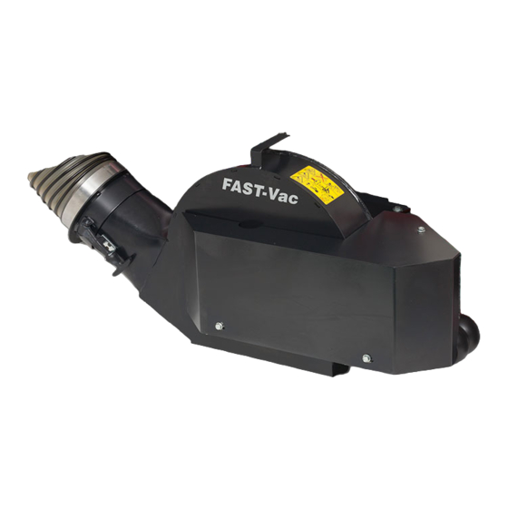
.-4415
Double & Triple Bag Grass Collection Systems
Double Bag Collection System for:
Ferris 1000Z Series - 48" & 52" Mowers
Derby Colt ZT2148 & ZT2352 - 48" & 52" Mowers
Ferris Industries
5375 North Main Street
Munnsville, NY 13409
800-933-6175
OPERATOR'S
MANUAL
with Blower Setup Instructions
Triple Bag Collection System for:
Ferris IS3000Z Series - 61" Mower
Derby Stallion ZT2561 - 61" Mower
22860
Rev. 9/2001
TP 100-7040-01-AT-FD
Advertisement
Table of Contents

Related Manuals for Ferris 1000z Series


Summary of Contents for Ferris 1000z Series
- Page 1 .-4415 Double & Triple Bag Grass Collection Systems Double Bag Collection System for: Ferris 1000Z Series - 48” & 52” Mowers Derby Colt ZT2148 & ZT2352 - 48” & 52” Mowers Ferris Industries 5375 North Main Street Munnsville, NY 13409 800-933-6175 OPERATOR’S...
- Page 2 This warranty shall apply ONLY if the warranty registration form has been completed and returned to Ferris Industries, Inc. within 20 days from the date of delivery. Ferris Industries, Inc. (Ferris) warrants, in accordance with the provisions below, to the original purchaser for the period of twenty-four (24) months from the date of delivery of a Ferris mower that the mower is free from defects in material or workmanship.
-
Page 3: Table Of Contents
Model Description Name Unit MODEL Dealer Name © Copyright 2001 Ferris Industries, Inc. All Rights Reserved. Printed in USA. TP 100-7040-01-AT-FD I I N N I I T T I I A A L L I I N N S S T T A A L L L L A A T T I I O O N N & & A A S S S S E E M M B B L L Y Y 6 6 1 1 ”... -
Page 4: General Warnings
Safety Rules & Information Read these safety rules and follow them closely. Failure to obey these rules could result in loss of control of unit, severe personal injury or death to you, or bystanders, or damage to property or equipment. The tri- angle in text signifies important cautions or warnings which must be followed. -
Page 5: Mowing With The Double / Triple Catcher
MOWING WITH THE DOUBLE / TRIPLE CATCHER Always operate with throttle at full speed when mowing. Grass should be cut often, and not too short. If grass is too long or lush it may be necessary to keep ground speed to a minimum or to cut only half the width of the mower to prevent clogging. -
Page 6: Remove Discharge Chute
Initial Installation & Assembly 48” & 52” DOUBLE-BAG COLLECTION SYSTEM BLOWER MOUNT & DRIVE GROUP Remove Discharge Chute 1. Park machine on a flat, level surface and apply the parking brake. 2. Remove the discharge chute and save. Save springs and spacer (Derby Colt only). Release Mower Drive Belt Tension 1. -
Page 7: Install Spindle Pulley
Install Spindle Pulley 1. Apply an anti-seize compound to the spindle shaft. Install the new, double spindle pulley (C, FIgure 4) on the shaft with the smaller pulley facing up with the 5/8” nylon lock nut (A), 5/8” washer (B) and 1/4” key (D) and tighten to 85-95 ft./lbs. - Page 8 48” & 52” Blower Mount & Drive Installation 2. While holding the mount plate vertical and against the chute mount tabs, place the spacers on the mower deck in the recesses of the mount plate. Make sure they are at the bottom of the recess (see Figure 7).
-
Page 9: Blower Preparation
Blower Preparation 1. Remove the belt guard (A, Figure 9) and hardware (B & C) from the blower housing and set aside. NOTE: Record the model and serial number of the blower on the warranty registration card and in the space provided on Page 1. - Page 10 48” & 52” Blower Mount & Drive Installation 6. Install the bearing (B, Figure 11) on the shaft with the grease fitting pointing towards the discharge of the blower. Secure with the 7/16-14 x 1-1/2” bolts (A) and 7/16-14 nylon lock nuts (C) as shown. Tighten the setscrew in the collar of the bearing.
-
Page 11: Install Blower & Belt Guard
Install Blower & Belt Guard 1. Install the blower onto the chute mount tabs with the blower mount tabs towards the rear. Secure with the retainer pin and hair pin. Make sure the handle of the retaining pin is pointing down. 2. -
Page 12: Remove Discharge Chute
Initial Installation & Assembly 61” TRIPLE-BAG COLLECTION SYSTEM BLOWER MOUNT & DRIVE GROUP Remove Discharge Chute 1. Park machine on a flat, level surface and apply the parking brake. 2. Remove the discharge chute and save. Save springs and spacer (Derby Stallion only). Release Mower Drive Belt Tension 1. -
Page 13: Install Spindle Pulley
Install Spindle Pulley 1. Apply an anti-seize compound to the spindle shaft. Install the new, double spindle pulley (C, Figure 22) on the shaft with the smaller pulley facing up with the 5/8” nylon lock nut (A), 5/8” washer (B) and 1/4” key (D) and tighten to 85-95 ft./lbs. -
Page 14: Blower Preparation
61” Blower Mount & Drive Installation Blower Preparation 1. Remove the belt guard (A, Figure 24) and hardware (B & C) from the blower housing and set aside. NOTE: Record the model and serial number of the blower on the warranty registration card and in the space provided on Page 1. - Page 15 6. Install the bearing (B, Figure 26) on the shaft with the grease fitting pointing towards the discharge of the blower. Secure with the four 7/16 x 1-1/2” bolts (A) and 716-14 nylon lock nuts (C) as shown. Tighten the setscrew in the collar of the bearing. 7.
- Page 16 61” Blower Mount & Drive Installation 11. Loosely install the blower brace (A, Figure 28), 3/8- 16 x 1” bolts (B) and 3/8” washers (C) as shown. These fasteners will be tightened in a later step. 12. Install the blower pulley and key with the hub facing OUTWARD away from the bearing and hold against the bearing.
-
Page 17: Install Blower & Belt Guard
Install Blower & Belt Guard 1. Install the blower assembly onto the mount bar (B, Figure 31). Push on the blower from the outside to obtain a tight fit between the blower housing and mower deck. Tighten the 3/8” x 1” bolts (C) that fas- ten the mount bar to the mower deck. -
Page 18: Reattaching Discharge Chute
Discharge Chute Reattachment MOWING WITHOUT THE BLOWER For operation without the blower, the deflector must be properly installed in the down position and retained by the spring latch (Derby models only). To remove the blower, reverse the installation steps. Reattaching the Discharge Chute See Figure 33. -
Page 19: Torque Specification Chart
Hardware Identification & Torque Specifications Common Hardware Types Hex Head Capscrew Carriage Bolt Standard Hardware Sizing When a washer or nut is identified as 1/2”, this is the Nominal size , meaning the inside diameter is 1/2 inch; if a second number is present it represent the threads per inch When bolt or capscrew is identified as 1/2 - 16 x 2”, this means the Nominal size , or body diameter is 1/2 inch;...