Table of Contents
Advertisement
Quick Links
MODEL G0654
6" JOINTER w/ MOBILE BASE
OWNER'S MANuAL
Copyright © January, 2008 By grizzly industrial, inC. revised June, 2013 (dm)
WARNING: NO pORTION Of ThIS MANuAL MAy BE REpRODucED IN ANy ShApE
OR fORM WIThOuT ThE WRITTEN AppROvAL Of GRIzzLy INDuSTRIAL, INc.
For maChines manuFaCtured sinCe 9/07 #Bl10265 printed in China
Advertisement
Table of Contents

Related Manuals for Grizzly G0654


Summary of Contents for Grizzly G0654
- Page 1 6" JOINTER w/ MOBILE BASE OWNER'S MANuAL Copyright © January, 2008 By grizzly industrial, inC. revised June, 2013 (dm) WARNING: NO pORTION Of ThIS MANuAL MAy BE REpRODucED IN ANy ShApE OR fORM WIThOuT ThE WRITTEN AppROvAL Of GRIzzLy INDuSTRIAL, INc.
- Page 2 This manual provides critical safety instructions on the proper setup, operation, maintenance, and service of this machine/tool. Save this document, refer to it often, and use it to instruct other operators. Failure to read, understand and follow the instructions in this manual may result in fire or serious personal injury—including amputation, electrocution, or death.
-
Page 3: Table Of Contents
Table of contents INTRODucTION ..........2 SEcTION 5: AccESSORIES ......32 machine description ........2 SEcTION 6: MAINTENANcE ......34 Contact info............ 2 schedule ............34 manual accuracy ........... 2 Cleaning ............34 identification ........... 3 lubrication ........... 34 machine data sheet ........4 v-Belt ............ -
Page 4: Introduction
For your convenience, we always keep current www.grizzly.com. grizzly manuals available on our website at www. grizzly.com. any updates to your machine will be alternatively, you can call our technical support reflected in these manuals as soon as they are for help. -
Page 5: Identification
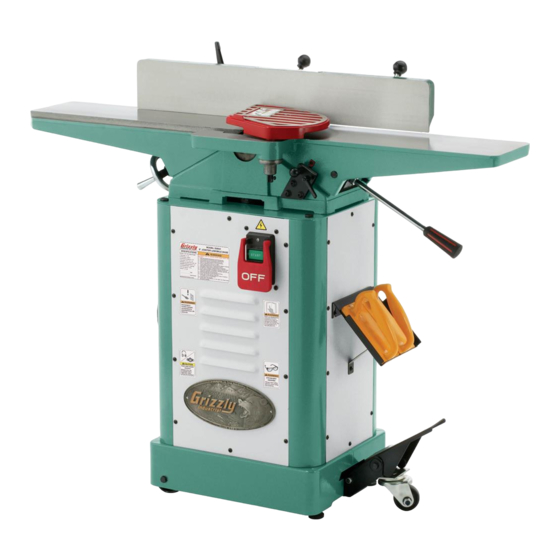
Identification figure 1. model g0654 identification. A. outfeed table B. Fence c. Fence tilt lever D. Cutterhead guard E. Fence lock Fence tilt handle G. infeed table h. infeed table adjustment lever on/oFF switch push Block holder K. depth scale infeed table lock M. -
Page 6: Machine Data Sheet
Machine Data Sheet MACHINE DATA SHEET Customer Service #: (570) 546-9663 · To Order Call: (800) 523-4777 · Fax #: (800) 438-5901 MODEL G0654 6" X 46" JOINTER Product Dimensions: Weight................................231 lbs. Width (side-to-side) x Depth (front-to-back) x Height............... 46 x 21-1/4 x 37-3/4 in. Footprint (Length x Width)...................... - Page 7 Fence Information Fence Length............................29-3/8 in. Fence Width............................1-3/16 in. Fence Height............................4-1/2 in. Fence Stops..........................45, 90, 135 deg. Cutterhead Information Cutterhead Type............................3 Knife Cutterhead Diameter..........................2-1/2 in. Cutterhead Speed..........................4800 RPM Knife Information Number of Knives............................. 3 Knife Type..........................
-
Page 8: Section 1: Safety
SEcTION 1: SAfETy for your Own Safety, Read Instruction Manual Before Operating This Machine The purpose of safety symbols is to attract your attention to possible hazardous conditions. This manual uses a series of symbols and signal words intended to convey the level of impor- tance of the safety messages. - Page 9 WEARING pROpER AppAREL. do not wear fORcING MAchINERy. do not force machine. clothing, apparel or jewelry that can become it will do the job safer and better at the rate for entangled in moving parts. always tie back or which it was designed. cover long hair.
-
Page 10: Additional Safety For Jointers
Additional Safety for Jointers JOINTER INJuRy RISKS. Familiarize yourself INSpEcTING STOcK. to reduce the risk of with the main injury risks associated with joint- kickback injuries or machine damage, thoroughly ers—always use common sense and good judge- inspect and prepare the workpiece before cutting. ment to reduce your risk of injury. -
Page 11: Section 2: Power Supply
SEcTION 2: pOWER SuppLy Availability Before installing the machine, consider the avail- ability and proximity of the required power supply Serious injury could occur if you connect circuit. if an existing circuit does not meet the the machine to power before completing the requirements for this machine, a new circuit must setup process. -
Page 12: Extension Cords
Grounding & plug Requirements Improper connection of the equipment-grounding wire can result in a risk of electric shock. The This machine MUST be grounded. In the event wire with green insulation (with or without yellow of certain malfunctions or breakdowns, grounding stripes) is the equipment-grounding wire. -
Page 13: Section 3: Setup
SEcTION 3: SETup Items Needed for unpacking Setup Your machine was carefully packaged for safe transportation. Remove the packaging materials from around your machine and inspect it. If you the following items are needed to complete the setup process, but are not included with your discover any damage, please call us immediately at (570) 546-9663 for advice. -
Page 14: Inventory
Inventory The following is a list of items shipped with your machine. Before beginning setup, lay these items out and inventory them. If any non-proprietary parts are missing (e.g. a nut or a washer), we will gladly replace them; or for the sake of expediency, replacements can be obtained at your local hardware store. - Page 15 fasteners (and where used) Tools (not shown) hex Bolts ⁄ "-16 x 1" (Cabinet support) .... 4 hex Wrench 2.5mm ........... 1 Flange Bolts m6-1 x 12 (Bottom plate) ..... 8 hex Wrench 3mm ..........1 Flat Washers 6mm (Bottom plate) ....8 hex Wrench 4mm ..........
-
Page 16: Cleanup
cleanup Gasoline and petroleum products have low flash the unpainted surfaces of your machine are points and can explode coated with a heavy-duty rust preventative that or cause fire if used to prevents corrosion during shipment and storage. clean machinery. Avo i d this rust preventative works extremely well, but it u sing t h e s e p r o du c t s will take a little time to clean. -
Page 17: Site Considerations
Site considerations Weight Load Physical Environment Refer to the Machine Data Sheet for the weight The physical environment where the machine is of your machine. Make sure that the surface upon operated is important for safe operation and lon- which the machine is placed will bear the weight gevity of machine components. -
Page 18: Assembly
Assembly Fasten the top plate to the cabinet supports with the (4) ⁄ "-16 x 1" hex bolts, as shown in figure 9, so the flat side is up and the single elliptical slot is on the wheel side of the cabi- To assemble the jointer: net. - Page 19 Carefully place the cabinet on its left side, hex Bolt m8-1.25 x 50 and secure the dust chute to the top plate flanges and left panel with (6) m6-1 x 12 Flat Washer 8mm flange bolts, 6mm flat washers, and m6-1 hex nuts (figures 11 &...
- Page 20 13. Fasten the jointer table assembly to the cabi- place the motor on the dust chute and align the mounting holes, making sure the pulley net with the (3) m10-1.5 hex nuts and 10mm faces the v-belt slot (figure 15). lock washers, as shown in figure 17.
- Page 21 16. loosen the motor or cutterhead pulley set 21. attach the dust port to the left cabinet panel screws and move the pulleys in or out as and dust chute with (4) #10-24 x ⁄ " flange needed to bring them into alignment. screws, as shown in figure 21.
- Page 22 23. remove the lock nut and flat washer (figure 23) from the fence lock handle bolt, place the fence on the jointer, and insert the bolt tilt lever through the slot in the carriage, making sure the carriage fits over the key (see figure 24). Flat Washer figure 25.
- Page 23 29. install the rear guard onto the carriage with the two phillips head screws and flat wash- ers already on the fence support, as shown in figure 28. phillips head screw rear guard figure 30. phillips head screw installed on cutterhead guard.
-
Page 24: Dust Collection
Dust collection Setting Outfeed Table height the outfeed table height must be level with the This machine creates substantial amounts knives when they are at top-dead-center. if the of dust during operation. Breathing air- outfeed table is set too low, the workpiece will be borne dust on a regular basis can result in tapered from front to back. -
Page 25: Test Run
Recommended —if your outfeed table is correctly set, no adjustments are necessary. Adjustments —if the knife lifts the straightedge off the table or the table is below the straightedge, loosen the outfeed table lock, and adjust For your convenience, the adjustments listed the outfeed table height with the hand below have been performed at the factory and no wheel until the straightedge just touches a... -
Page 26: Section 4: Operations
Regardless of the content in this sec- tion, Grizzly Industrial will not be held liable for accidents caused by lack of training. infeed... - Page 27 fence Movement: the fence has a lock that fence Tilting: the tilt lock (see figure 38) keeps it in position (see figure 37). to move the secures the fence at any position in the available fence, loosen the lock and slide the fence where range.
-
Page 28: Stock Inspection & Requirements
Stock Inspection & Scrape all glue off the workpiece before • jointing. glue deposits on the workpiece, Requirements hard or soft, will gum up the cutterhead and produce poor results. Remove foreign objects from • follow these rules when choosing and joint- workpiece. -
Page 29: Squaring Stock
Edge Joint on the Jointer: the concave edge of the workpiece is jointed flat with the jointer (see figure 43). Before turning the jointer ON, make sure the outfeed table height is properly set (refer to Setting Outfeed Table height on page 22 for detailed instructions) to avoid workpiece kickback and to ensure good results. -
Page 30: Surface Planing
Surface planing To surface plane on the jointer: read and understand SEcTION 1: SAfETy, beginning on page 6. the purpose of surface planing on the jointer is to make one flat face on a piece of stock (see make sure your stock has been inspected figures 45 &... -
Page 31: Edge Jointing
Edge Jointing To edge joint on the jointer: read and understand SEcTION 1: SAfETy, beginning on page 6. the purpose of edge jointing is to produce a fin- ished, flat-edged surface (see figures 47 & 48) make sure your stock has been inspected that is suitable for joinery or finishing. -
Page 32: Bevel Cutting
Bevel cutting To bevel cut on the jointer: read and understand SEcTION 1: SAfETy, beginning on page 6. the purpose of bevel cutting is to cut a specific angle into the edge of a workpiece (see figures make sure your stock has been inspected 49 &... -
Page 33: Rabbet Cutting
Rabbet cutting To rabbet cut on the jointer: read and understand SEcTION 1: SAfETy, beginning on page 6. the purpose of rabbet cutting is to remove a sec- tion of the workpiece edge (see figures 51 & 52). make sure your stock has been inspected When combined with another rabbet cut edge, the for dangerous conditions as described in the rabbet joints create a simple, yet strong method of... -
Page 34: Section 5: Accessories
Gun Treatment 4.5 oz Spray ® To reduce this risk, only install accessories recommended for this machine by Grizzly. NOTICE Refer to our website or latest catalog for additional recommended accessories. h7764—6" Byrd Shelix cutterhead ®... - Page 35 4" the perfectionist! dust ports. g1536 h1052 g2974 g4679 figure 57. grizzly dial Calipers. ® g1545 g1843 figure 59. dust collection accessories. www.grizzly.com 1-800-523-4777...
-
Page 36: Section 6: Maintenance
SEcTION 6: MAINTENANcE Lubrication To reduce risk of shock or accidental startup, always since all bearings are sealed and permanently disconnect machine from lubricated, simply leave them alone until they power before adjustments, need to be replaced. do not lubricate them. maintenance, or service. -
Page 37: V-Belt
remove the rear access panel and belt Gibs: lower the infeed and outfeed table to guard. access the gibs. annually place a couple drops of oil at the top of each gib and move the tables up using a 12mm wrench, loosen the motor and down to distribute the oil. -
Page 38: Section 7: Service
SEcTION 7: SERvIcE Review the troubleshooting and procedures in this section if a problem develops with your machine. If you need replacement parts or additional help with a procedure, call our Technical Support at (570) 546-9663. Note: Please gather the serial number and manufacture date of your machine before calling. Troubleshooting Motor &... - Page 39 Motor & Electrical continued symptom possible Cause possible solution machine has vibra- 5. motor mount loose/broken. 5. tighten/replace. tion or noisy opera- 6. machine is incorrectly mounted or sits 6. relocate machine or adjust feet to level jointer. tion. unevenly. 7.
-
Page 40: Inspecting Knives
Inspecting Knives Carefully inspect how the gauge touches the cutterhead and the knife. — if both outside legs of the gauge sit firmly the height of the knives can be easily and quickly on the cutterhead and the middle pad just inspected with the included knife setting gauge. - Page 41 Tools Needed using a 2.5mm hex wrench, rotate the jack Knife setting gauge .......... 1 screws (see figure 67) in the access holes to hex Wrench 2.5mm ........... 1 raise or lower the knife. When the knife is set Wrench 8mm ............. 1 correctly, it will barely touch the middle pad of the knife setting jig.
-
Page 42: Calibrating Infeed Table
calibrating Infeed using a screwdriver, adjust the scale pointer exactly to “0”, as shown in figure 70. Table the infeed table height is calibrated by adjusting depth stop the depth scale and depth stop knob. Knob depth scale pointer Tools Needed straightedge ............ -
Page 43: Setting Fence Stops
Setting fence Stops adjust the 45˚ inward fence stop bolt until it makes contact with the back of the fence bracket. the fence stops simplify the task of adjusting the retighten the jam nut loosened in Step 2. fence to 45˚ inward, 90˚, and 45˚ outward (135˚). To set the 90˚... -
Page 44: Adjusting Gibs
Adjusting Gibs To set the 45˚ outward fence stop: pull the plunger out (see figure 74 on page 41). the table gibs eliminate excessive play in the table movement, and control how easy the tables using a sliding bevel adjusted to 135˚, adjust move up and down. -
Page 45: Wiring Diagram
Ground (As Recommended) match your machine. Always use the wiring diagram View this page in color at inside the motor junction box. www.grizzly.com. PUSH BUTTON SWITCH (viewed from behind) see figure 78 figure 78. switch wiring. Ground MOTOR Ground Start... -
Page 46: Stand Parts Breakdown
Stand parts Breakdown 47-1 47-4 47-2 47-5 47-3 65-18 65-17 65-19 65-16 65-1 65-15 65-3 65-14 65-4 65-13 65-5 65-12 65-6 65-7 65-11 65-8 65-10 65-2 65-9 -44- Model G0654 (Mfg. Since 9/07) -
Page 47: Stand Parts List
Stand parts List REF PART # DESCRIPTION REF PART # DESCRIPTION P0654001 BELT GUARD ASSEMBLY P0654045 PUSH BLOCK HOLDER PFB01M FLANGE BOLT M6-1 X 12 P0654046 BACK PANEL PW03M FLAT WASHER 6MM P0654047 MOTOR 1HP 110V PN01M HEX NUT M6-1 47-1 P0654047-1 FAN COVER... -
Page 48: Table Parts Breakdown
Table parts Breakdown 195-1 195-2 195-3 -46- Model G0654 (Mfg. Since 9/07) -
Page 49: Table Parts List
Table parts List REF PART # DESCRIPTION REF PART # DESCRIPTION P0654101 PSS53M SET SCREW M5-.8 X 12 P0654102 KNIFE P0654147 INDEX PIN M6-1 X 14 P0654103 GIB BOLT P0654148 COMPRESSION SPRING P0654104 CUTTERHEAD PULLEY P0654149 PLUNGER HOUSING P0654105 RIGHT HAND BEARING SUPPORT P0654150 BALL KNOB M6-1 P6203... -
Page 50: Fence Parts Breakdown
fence parts Breakdown -48- Model G0654 (Mfg. Since 9/07) -
Page 51: Fence Parts List
fence parts List REF PART # DESCRIPTION REF PART # DESCRIPTION P0654201 FENCE PN03M HEX NUT M8-1.25 P0654203 BALL KNOB M10-1.5 P0654222 ALIGNMENT PIN 7 X 24 P0654204 STUD M10-1.5 P0654223 LEFT BRACKET P0654203 BALL KNOB M10-1.5 P0654224 SPECIAL SCREW M8-1.25 P0654204 STUD M10-1.5 P0654225... -
Page 52: Label Placement
MuST maintain the original location and readability of the labels on the machine. If any label is removed or becomes unreadable, REpLAcE that label before using the machine again. contact Grizzly at (800) 523-4777 or www.grizzly.com to order new labels. -50-... - Page 53 Would you recommend Grizzly Industrial to a friend? _____ Yes _____No Would you allow us to use your name as a reference for Grizzly customers in your area? Note: We never use names more than 3 times. _____ Yes _____No 10.
- Page 54 FOLD ALONG DOTTED LINE Place Stamp Here GRIZZLY INDUSTRIAL, INC. P.O. BOX 2069 BELLINGHAM, WA 98227-2069 FOLD ALONG DOTTED LINE Send a Grizzly Catalog to a friend: Name_______________________________ Street_______________________________ City______________State______Zip______ TAPE ALONG EDGES--PLEASE DO NOT STAPLE...
-
Page 55: Warranty And Returns
WARRANTY AND RETURNS Grizzly Industrial, Inc. warrants every product it sells for a period of 1 year to the original purchaser from the date of purchase. This warranty does not apply to defects due directly or indirectly to misuse, abuse, negligence, accidents, repairs or alterations or lack of maintenance.