Table of Contents
Advertisement
Advertisement
Table of Contents
Troubleshooting

Related Manuals for Gigabyte GA-MA74GM-S2H


Summary of Contents for Gigabyte GA-MA74GM-S2H
- Page 1 GA-MA74GM-S2H AM2+/AM2 socket motherboard for AMD Phenom FX processor/AMD Phenom X4 processor/ AMD Phenom X3 processor/AMD Athlon X2 processor/ AMD Athlon processor/AMD Sempron X2 processor/ AMD Sempron processor User's Manual Rev. 1003 12ME-MA74GMS2H-1003R...
-
Page 3: Identifying Your Motherboard Revision
GIGABYTE's prior written permission. Documentation Classifications In order to assist in the use of this product, GIGABYTE provides the following types of documentations: For detailed product information, carefully read the User's Manual. For instructions on how to use GIGABYTE's unique features, read or download the information on/from the Support\Motherboard\Technology Guide page on our website. -
Page 4: Table Of Contents
Table of Contents Box Contents ......................... 6 Optional Items......................... 6 GA-MA74GM-S2H Motherboard Layout ................ 7 Block Diagram........................ 8 Chapter 1 Hardware Installation ..................9 Installation Precautions ..................9 Product Specifications ..................10 Installing the CPU and CPU Cooler .............. 13 1-3-1 Installing the CPU .................... - Page 5 Chapter 3 Drivers Installation ..................53 Installing Chipset Drivers ................53 Software Applications ..................54 Driver CD Information ..................54 Hardware Information ..................55 Contact Us ..................... 55 Chapter 4 Unique Features ..................57 Xpress Recovery2 ..................57 BIOS Update Utilities ..................62 4-2-1 Updating the BIOS with the Q-Flash Utility ............
-
Page 6: Box Contents
Box Contents GA-MA74GM-S2H motherboard Motherboard driver disk User's Manual Quick Installation Guide One IDE cable and one floppy disk drive cable Two SATA 3Gb/s cables I/O Shield • The box contents above are for reference only and the actual items shall depend on product package you obtain. The box contents are subject to change without notice. -
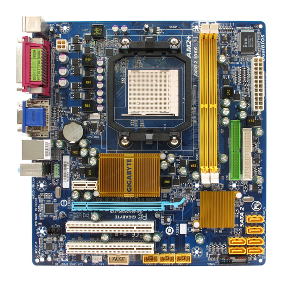
Page 7: Ga-Ma74Gm-S2H Motherboard Layout
GA-MA74GM-S2H Motherboard Layout KB_USB BIOS ATX_12V Socket AM2 CPU_FAN BATTERY GA-MA74GM-S2H AUDIO F_AUDIO PCIE_1 AMD 740G PCIE_16 Realtek 8111C SATAII 5 AMD SB700 PCI1 SATAII 4 CD_IN SATAII_2 SATAII_ 3 PCI2 PWR_LED CLR_CMOS F_PANEL CODEC SATAII_1 SATAII_0 SPDIF_O SYS_FAN - 7 -... -
Page 8: Block Diagram
Block Diagram PCIe CLK CPU CLK+/-(200 MHz) (100 MHz) Socket AM2 DDR2 800/667 MHz DIMM Dual Channel Memory 1 PCI Express x16 Hyper Transport Bus GFX CLK (100 MHz) PCI Express x16 PCI Express Bus D-Sub AMD 740G DVI-D or HDMI (Note) 8111C PCIe CLK... -
Page 9: Chapter 1 Hardware Installation
Chapter 1 Hardware Installation Installation Precautions The motherboard contains numerous delicate electronic circuits and components which can become damaged as a result of electrostatic discharge (ESD). Prior to installation, carefully read the user's manual and follow these procedures: Prior to installation, do not remove or break motherboard S/N (Serial Number) sticker or •... -
Page 10: Product Specifications
X3 processor/AMD Athlon X2 processor/ AMD Athlon processor/AMD Sempron X2 processor/ AMD Sempron processor (Go to GIGABYTE's website for the latest CPU support list.) Front Side Bus 2000 MHz FSB Chipset North Bridge: AMD 740G South Bridge: AMD SB700 Memory 2 x 1.8V DDR2 DIMM sockets supporting up to 8 GB of system memory... - Page 11 Internal Connectors 1 x 24-pin ATX main power connector 1 x 4-pin ATX 12V power connector 1 x floppy disk drive connector 1 x IDE connector 6 x SATA 3Gb/s connectors 1 x CPU fan header 1 x system fan header 1 x front panel header 1 x front panel audio header 1 x CD In connector...
- Page 12 Unique Features Support for @BIOS Support for Download Center Support for Q-Flash Support for EasyTune (Note 5) Support for Xpress Install Support for Xpress Recovery2 Support for Virtual Dual BIOS Bundled Software Norton Internet Security (OEM version) Operating System Support for Microsoft Windows Vista/XP ®...
-
Page 13: Installing The Cpu And Cpu Cooler
Read the following guidelines before you begin to install the CPU: • Make sure that the motherboard supports the CPU. (Go to GIGABYTE's website for the latest CPU support list.) • Always turn off the computer and unplug the power cord from the power outlet before installing the CPU to prevent hardware damage. - Page 14 B. Follow the steps below to correctly install the CPU into the motherboard CPU socket. Before installing the CPU, make sure to turn off the computer and unplug the power cord from the power outlet to prevent damage to the CPU. CPU Socket Locking Lever Step 1:...
-
Page 15: Installing The Cpu Cooler
1-3-2 Installing the CPU Cooler Follow the steps below to correctly install the CPU cooler on the CPU. (The following procedure uses the GIGABYTE cooler as the example.) Step 1: Step 2: Apply an even and thin layer of thermal grease Place the CPU cooler on the CPU. -
Page 16: Installing The Memory
• Make sure that the motherboard supports the memory. It is recommended that memory of the same capacity, brand, speed, and chips be used. (Go to GIGABYTE's website for the latest memory support list.) • Always turn off the computer and unplug the power cord from the power outlet before installing the memory to prevent hardware damage. -
Page 17: Installing A Memory
1-4-2 Installing a Memory Before installing a memory module , make sure to turn off the computer and unplug the power cord from the power outlet to prevent damage to the memory module. DDR2 DIMMs are not compatible to DDR DIMMs. Be sure to install DDR2 DIMMs on this motherboard. -
Page 18: Installing An Expansion Card
Installing an Expansion Card Read the following guidelines before you begin to install an expansion card: • Make sure the motherboard supports the expansion card. Carefully read the manual that came with your expansion card. • Always turn off the computer and unplug the power cord from the power outlet before installing an expansion card to prevent hardware damage. -
Page 19: Back Panel Connectors
Back Panel Connectors USB Port The USB port supports the USB 2.0/1.1 specification. Use this port for USB devices such as an USB keyboard/mouse, USB printer, USB flash drive and etc. PS/2 Keyboard Port Use the port to connect a PS/2 keyboard. Parallel Port Use the parallel port to connect devices such as a printer, scanner and etc. - Page 20 A. Dual Display Configurations: This motherboard provides three ports for video output: DVI-D, HDMI and D-Sub. The table below shows the supported dual display configurations. Dual Combination Supported or Not Display DVI-D + D-Sub DVI-D + HDMI HDMI + D-Sub B.
-
Page 21: Internal Connectors
Internal Connectors ATX_12V F_PANEL F_AUDIO CPU_FAN CD_IN SYS_FAN SPDIF_O F_USB1 / F_USB2 / F_USB3 / F_USB4 SATAII_0/_1/_2/_3/ 4/ 5 PWR_LED CLR_CMOS BATTERY Read the following guidelines before connecting external devices: • First make sure your devices are compliant with the connectors you wish to connect. •... - Page 22 1/2) ATX_12V/ATX (2x2 12V Power Connector and 2x12 Main Power Connector) With the use of the power connector, the power supply can supply enough stable power to all the components on the motherboard. Before connecting the power connector, first make sure the power supply is turned off and all devices are properly installed.
- Page 23 3/4) CPU_FAN/SYS_FAN (Fan Headers) The motherboard has a 4-pin CPU fan header (CPU_FAN) and a 4-pin (SYS_FAN) system fan headers. Most fan headers possess a foolproof insertion design. When connecting a fan cable, be sure to connect it in the correct orientation (the black connector wire is the ground wire). The motherboard supports CPU fan speed control, which requires the use of a CPU fan with fan speed control design.
- Page 24 6) IDE (IDE Connector) The IDE connector supports up to two IDE devices such as hard drives and optical drives. Before attaching the IDE cable, locate the foolproof groove on the connector. If you wish to connect two IDE devices, remember to set the jumpers and the cabling according to the role of the IDE devices (for example, master or slave).
-
Page 25: Battery
8) PWR_LED (System Power LED Header) This header can be used to connect a system power LED on the chassis to indicate system power status. The LED is on when the system is operating. The LED keeps blinking when the system is in S1 sleep state. -
Page 26: Front Panel Header
10) F_PANEL (Front Panel Header) Connect the power switch, reset switch, speaker and system status indicator on the chassis front panel to this header according to the pin assignments below. Note the positive and negative pins before connecting the cables. Message/Power/ Power Sleep LED... -
Page 27: Cd In Connector
11) F_AUDIO (Front Panel Audio Header) The front panel audio header supports Intel High Definition audio (HD) and AC'97 audio. You may connect your chassis front panel audio module to this header. Make sure the wire assignments of the module connector match the pin assignments of the motherboard header. Incorrect connection between the module connector and the motherboard header will make the device unable to work or even damage it. - Page 28 13) SPDIF_O (S/PDIF Out Header) This header supports digital S/PDIF out and connects a S/PDIF digital audio cable (provided by expansion cards) for digital audio output from your motherboard to certain expansion cards like graphics cards and sound cards. For example, some graphics cards may require you to use a S/PDIF digital audio cable for digital audio output from your motherboard to your graphics card if you wish to connect an HDMI display to the graphics card and have digital audio output from the HDMI display at the same time.
- Page 29 15) COM (Serial Port Header) The COM header can provide one serial port via an optional COM port cable. For purchasing the optional COM port cable, please contact the local dealer. Pin No. Definition NDCD - NSIN NSOUT NDTR - NDSR - NRTS - NCTS -...
-
Page 30: Clear Cmos Jumper
17) CLR_CMOS (Clearing CMOS Jumper) Use this jumper to clear the CMOS values (e.g. date information and BIOS configurations) and reset the CMOS values to factory defaults. To clear the CMOS values, place a jumper cap on the two pins to temporarily short the two pins or use a metal object like a screwdriver to touch the two pins for a few seconds. -
Page 31: Chapter 2 Bios Setup
To see more advanced BIOS Setup menu options, you can press <Ctrl> + <F1> in the main menu of the BIOS Setup program. To upgrade the BIOS, use either the GIGABYTE Q-Flash or @BIOS utility. Q-Flash allows the user to quickly and easily upgrade or back up BIOS without entering the •... -
Page 32: Startup Screen
Startup Screen The following screen may appear when the computer boots. Award Modular BIOS v6.00PG, An Energy Star Ally Copyright (C) 1984-2008, Award Software, Inc. AMD RS740 BIOS for GA-MA74GM-S2H D4a Motherboard Model BIOS Version Function Keys <DEL>: BIOS Setup/Q-Flash <F9>: XpressRecovery2 <F12>: Boot Menu <End>: Qflash 01/25/2008-RS740-SB700-6A669G04C-00 Function Keys: <DEL>: BIOS Setup/Q-Flash... -
Page 33: The Main Menu
The Main Menu Once you enter the BIOS Setup program, the Main Menu (as shown below) appears on the screen. Use arrow keys to move among the items and press <Enter> to accept or enter a sub-menu. (Sample BIOS Version: D4a) CMOS Setup Utility-Copyright (C) 1984-2008 Award Software Standard CMOS Features Load Fail-Safe Defaults... - Page 34 The Functions of the <F11> and <F12> keys (For the Main Menu Only) F11 : Save CMOS to BIOS This function allows you to save the current BIOS settings to a profile. You can create up to 8 profiles (Profile 1-8) and name each profile. First enter the profile name (to erase the default profile name, use the SPACE key) and then press <Enter>...
-
Page 35: Standard Cmos Features
Standard CMOS Features CMOS Setup Utility-Copyright (C) 1984-2008 Award Software Standard CMOS Features Date (mm:dd:yy) Wed, Jan 18 2008 Item Help Time (hh:mm:ss) 18:25:04 Menu Level IDE Channel 0 Master [None] IDE Channel 0 Slave [None] IDE Channel 1 Master [None] IDE Channel 1 Slave [None]... - Page 36 The following fields display your hard drive specifications. If you wish to enter the parameters manually, refer to the information on the hard drive. Capacity Approximate capacity of the currently installed hard drive. Cylinder Number of cylinders. Head Number of heads. Precomp Write precompensation cylinder.
-
Page 37: Advanced Bios Features
Advanced BIOS Features CMOS Setup Utility-Copyright (C) 1984-2008 Award Software Advanced BIOS Features Virtualization [Disabled] Item Help AMD K8 Cool&Quiet control [Auto] Menu Level Hard Disk Boot Priority [Press Enter] First Boot Device [Floppy] Second Boot Device [Hard Disk] Third Boot Device [CDROM] Password Check [Setup]... - Page 38 HDD S.M.A.R.T. Capability Enables or disables the S.M.A.R.T. (Self Monitoring and Reporting Technology) capability of your hard drive. This feature allows your system to report read/write errors of the hard drive and to issue warnings when a third party hardware monitor utility is installed. (Default: Disabled) Away Mode Enables or disables Away Mode in Windows XP Media Center operating system.
-
Page 39: Integrated Peripherals
Integrated Peripherals CMOS Setup Utility-Copyright (C) 1984-2008 Award Software Integrated Peripherals OnChip IDE Channel [Enabled] Item Help OnChip SATA Controller [Enabled] Menu Level OnChip SATA Type [Native IDE] x OnChip SATA Port4/5 Type [IDE] Onboard LAN Function [Enabled] Onboard LAN Boot ROM [Disabled] SMART LAN [Press Enter]... - Page 40 SMART LAN (LAN Cable Diagnostic Function) CMOS Setup Utility-Copyright (C) 1984-2008 Award Software SMART LAN Start detecting at Port..Item Help Menu Level Part1-2 Status = Open / Length Part3-6 Status = Open / Length Part4-5 Status = Open / Length Part7-8 Status = Open / Length...
- Page 41 Onboard Audio Function Enables or disables the onboard audio function. (Default: Enabled) If you wish to install a 3rd party add-in audio card instead of using the onboard audio, set this item to Disabled. OnChip USB Controller Enables or disables the integrated USB 1.1 controller. (Default: Enabled) USB EHCI Controller Enables or disables the integrated USB 2.0 controller.
-
Page 42: Power Management Setup
Power Management Setup CMOS Setup Utility-Copyright (C) 1984-2008 Award Software Power Management Setup ACPI Suspend Type [S1(POS)] Item Help Soft-Off by Power button [Instant-off] Menu Level USB Wake Up from S3 [Enabled] Modem Ring Resume [Disabled] PME Event Wake Up [Disabled] HPET Support (Note) - Page 43 PME Event Wake Up Allows the system to be awakened from an ACPI sleep state by a wake-up signal from a PCI or PCIe device. Note: To use this function, you need an ATX power supply providing at least 1A on the +5VSB lead.
-
Page 44: Pnp/Pci Configurations
PnP/PCI Configurations CMOS Setup Utility-Copyright (C) 1984-2008 Award Software PnP/PCI Configurations PCI1 IRQ Assignment [Auto] Item Help PCI2 IRQ Assignment [Auto] Menu Level : Move Enter: Select +/-/PU/PD: Value F10: Save ESC: Exit F1: General Help F5: Previous Values F6: Fail-Safe Defaults F7: Optimized Defaults PCI1 IRQ Assignment Auto... -
Page 45: Pc Health Status
PC Health Status CMOS Setup Utility-Copyright (C) 1984-2008 Award Software PC Health Status Reset Case Open Status [Disabled] Item Help Case Opened Menu Level Vcore 1.376V DDR2 1.8V 1.840V +3.3V 3.360V +12V 12.048V Current System Temperature Current CPU Temperature Current CPU FAN Speed 3375 RPM Current SYSTEM FAN Speed CPU Warning Temperature... - Page 46 CPU Smart FAN Control Enables or disables the CPU fan speed control function. Enabled allows the CPU fan to run at different speed according to the CPU temperature. You can adjust the fan speed with EasyTune based on system requirements. If disabled, CPU fan runs at full speed. (Default: Enabled) CPU Smart FAN Mode Specifies how to control CPU fan speed.
-
Page 47: Mb Intelligent Tweaker(M.i.t.)
MB Intelligent Tweaker(M.I.T.) CMOS Setup Utility-Copyright (C) 1984-2008 Award Software MB Intelligent Tweaker(M.I.T.) HT Link Frequency [Auto] Item Help CPU Clock Ratio [Auto] Menu Level (Note) Memory Controller Freq. [Auto] 1800Mhz CPU Host Clock Control [Auto] x CPU Frequency (MHz) PCIE Clock (MHz) [Auto] VGA Core Clock (MHz) - Page 48 PCIE Clock (MHz) Allows you to manually set the PCIe clock frequency. The adjustable range is from 100 MHz to 200 MHz. Auto sets the PCIe clock frequency to standard 100 MHz. (Default: Auto) VGA Core Clock (Mhz) Allows you to manually set the VGA Core clock. The adjustable range is from 200 MHz to 600 MHz. (Default: 400) Set Memory Clock Determines whether to manually set the memory clock.
-
Page 49: Load Fail-Safe Defaults
2-10 Load Fail-Safe Defaults CMOS Setup Utility-Copyright (C) 1984-2008 Award Software Standard CMOS Features Load Fail-Safe Defaults Advanced BIOS Features Load Optimized Defaults Integrated Peripherals Set Supervisor Password Power Management Setup Set User Password Load Fail-Safe Defaults (Y/N)? N PnP/PCI Configurations Save &... -
Page 50: Set Supervisor/User Password
2-12 Set Supervisor/User Password CMOS Setup Utility-Copyright (C) 1984-2008 Award Software Standard CMOS Features Load Fail-Safe Defaults Advanced BIOS Features Load Optimized Defaults Integrated Peripherals Set Supervisor Password Power Management Setup Set User Password PnP/PCI Configurations Save & Exit Setup Enter Password: PC Health Status Exit Without Saving... -
Page 51: Save & Exit Setup
2-13 Save & Exit Setup CMOS Setup Utility-Copyright (C) 1984-2008 Award Software Standard CMOS Features Load Fail-Safe Defaults Advanced BIOS Features Load Optimized Defaults Integrated Peripherals Set Supervisor Password Save to CMOS and EXIT (Y/N)? Y Power Management Setup Set User Password PnP/PCI Configurations Save &... - Page 52 GA-MA74GM-S2H Motherboard - 52 -...
-
Page 53: Chapter 3 Drivers Installation
Chapter 3 Drivers Installation • Before installing the drivers, first install the operating system. (The following instructions use Windows XP as the example operating system.) • After installing the operating system, insert the motherboard driver disk into your optional drive. The driver Autorun screen is automatically displayed which looks like that shown in the screen shot below. -
Page 54: Software Applications
Software Applications This page displays all the tools and applications that GIGABYTE develops and some free software. You may press the Install button following an item to install it. Driver CD Information This page provides information about the drivers, applications and tools in this driver disk. -
Page 55: Hardware Information
Hardware Information This page provides information about the hardware devices on this motherboard. Contact Us Check the contacts information of the GIGABYTE headquarter in Taiwan and the overseas branch offices on the last page of this manual. - 55 -... - Page 56 GA-MA74GM-S2H Motherboard - 56 -...
-
Page 57: Chapter 4 Unique Features
Chapter 4 Unique Features Xpress Recovery2 Xpress Recovery2 is a utility that allows you to quickly compress and back up your system data and perform restoration of it. Supporting NTFS, FAT32, and FAT16 file systems, Xpress Recovery2 can back up data on PATA and SATA hard drives and restore it. Before You Begin: •... - Page 58 Installation and Configuration (The following procedure uses Windows XP as the example operating system.) A. Installing Windows XP and Partitioning the Hard Drive 1. Set CD-ROM drive as the first boot device under "Advanced BIOS Features" in the BIOS Setup program.
- Page 59 4. After the operating system is installed, right-click the My Computer icon on your desktop and select Manage (Figure 4). Go to Computer Management to check disk allocation. Xpress Recovery2 will save the backup file to the unallocated space (black stripe along the top)(Figure 5). Please note that if there is no enough unallocated space, Xpress Recovery2 cannot save the backup file.
- Page 60 B. Accessing Xpress Recovery2 1. Boot from the motherboard driver disk to access Xpress Recovery2 for the first time. When you see the following message: Press any key to startup Xpress Recovery2 (Figure 8), press any key to enter Xpress Recovery2. Boot from CD/DVD: Figure 8 Press any key to startup XpressRecovery2..
- Page 61 D. Using the Restore Function in Xpress Recovery2 Select RESTORE to restore the backup to your hard drive in case the system breaks down. The RESTORE option will not be present if no backup is created before (Figure 13, 14). Figure 13 Figure 14 E.
-
Page 62: Bios Update Utilities
4-2-1 Updating the BIOS with the Q-Flash Utility A. Before You Begin: 1. From GIGABYTE's website, download the latest compressed BIOS update file that matches your motherboard model. 2. Extract the file and save the new BIOS file (e.g. MA74GS2H.F1) to your floppy disk, USB flash drive, or hard drive. - Page 63 B. Updating the BIOS When updating the BIOS, choose the location where the BIOS file is saved. The follow procedure assumes that you save the BIOS file to a floppy disk. Step 1: 1. Insert the floppy disk containing the BIOS file into the floppy disk drive. In the main menu of Q- Flash, use the up or down arrow key to select Update BIOS from Drive and press <Enter>.
- Page 64 Step 4: Press <Esc> and then <Enter> to exit Q-Flash and reboot the system. As the system boots, you should see the new BIOS version is present on the POST screen. Step 5: During the POST, press <Delete> to enter BIOS Setup. Select Load Optimized Defaults and press <Enter>...
-
Page 65: Updating The Bios With The @Bios Utility
BIOS or a system that is unable to start. 3. Do not use the C.O.M. (Corporate Online Management) function when using @BIOS. 4. GIGABYTE product warranty does not cover any BIOS damage or system failure resulting from an inadequate BIOS flashing. - Page 66 • If the BIOS update file for your motherboard is not present on the @BIOS server site, please manually download the BIOS update file from GIGABYTE's website and follow the instructions in "Update the BIOS without Using the Internet Update Function" below.
-
Page 67: Easytune 5 Pro
Display Area Displays the CPU frequency Function LEDs Shows the supported function(s) Live Update Go to GIGABYTE website to update EasyTune 5 Pro Help Opens EasyTune 5 Pro help file Exit/Minimize Quits or minimizes the EasyTune 5 Pro interface Turbo Boost... - Page 68 GA-MA74GM-S2H Motherboard - 68 -...
-
Page 69: Chapter 5 Appendix
Chapter 5 Appendix Configuring SATA Hard Drive(s) To configure SATA hard drive(s), follow the steps below: A. Install SATA hard drive(s) in your computer. B. Configure SATA controller mode in BIOS Setup. C . Configure a RAID array in RAID BIOS. (Note 1) D. - Page 70 B. Configuring SATA controller mode in BIOS Setup Make sure to configure the SATA controller mode correctly in system BIOS Setup . Step 1: Turn on your computer and press <Delete> to enter BIOS Setup during the POST (Power-On Self-Test). Ensure OnChip SATA Controller is enabled under Integrated Peripherals.
- Page 71 C. Configuring RAID set in RAID BIOS Enter the RAID BIOS setup utility to configure a RAID array. Skip this step if you do not want to create RAID. Step 1: After the POST memory test begins and before the operating system boot begins, look for a message which says "Press <Ctrl-F>...
- Page 72 FastBuild (tm) Utility (c) 2007 Advanced Micro Devices, Inc. Define LD Menu LD No RAID Mode Total Drv LD 1 RAID 0 Stripe Block: 64 KB Fast Init: Gigabyte Boundary: Cache Mode: WriteThru Drives Assignments Channel:ID Drive Model Capabilities Capacity (GB) Assignment 1:Mas WDC WD800JD-22LSA0 SATA 3G 80.02...
- Page 73 In the following procedure, we'll create RAID 0 as an example. 1. Under the RAID Mode section, press the <SPACE> key to select RAID 0. 2. Set the Stripe Block size. 64 KB is the default. 3. Under the Drives Assignments section, press the up or down arrow key to highlight a drive. 4.
- Page 74 Delete an Array The Delete Array menu option allows for deletion of disk array assignments. Deleting an existing disk array could result in loss of data. Record all array information including the array type, the disk members, and stripe block size in case you wish to undo a deletion. 1.
-
Page 75: Making A Sata Raid/Ahci Driver Diskette
5-1-2 Making a SATA RAID/AHCI Driver Diskette (Required for AHCI and RAID Mode) To successfully install operating system onto SATA hard drive(s) that is/are configured to RAID/AHCI mode, you need to install the SATA controller driver during the OS installation. Without the driver, the hard drive may not be recognized during the Windows setup process . -
Page 76: Installing The Sata Raid/Ahci Driver And Operating System
5-1-3 Installing the SATA RAID/AHCI Driver and Operating System You are ready to install Windows Vista/XP/2000 onto your hard drive(s). The following is an example of Windows XP and Vista installation. A. Installing Windows XP Step 1: Restart your system to boot from the Windows XP setup disk and press <F6> as soon as you see the message "Press F6 if you need to install a 3rd party SCSI or RAID driver"... - Page 77 Step 3: When Setup correctly recognizes the AMD SB700 SATA RAID/AHCI driver in the floppy disk, a controller menu similar to Figure 3 below will appear. Use the arrow keys to select AMD AHCI Compatible RAID Controller-x86 platform and press <Enter>. Windows Setup You have chosen to configure a SCSI Adapter for use with Windows, using a device support disk provided by an adapter manufacturer.
- Page 78 Step 4: After the SATA RAID/AHCI driver installation is completed, you can proceed with the Windows XP installation. WindowsXP Professional Setup Welcome to Setup. This port of the Setup program prepares Microsoft(R) Windows (R) XP to run on your computer. To set up Windows XP now, press ENTER.
- Page 79 B. Installing Windows Vista (Note) (The procedure below assumes that only one RAID array exists in your system.) Step 1: Restart your system to boot from the Windows Vista setup disk and perform standard OS installation steps. When a screen similar to that below appears (RAID hard drive will not be detected at this stage), select Load Driver.
- Page 80 Step 3: When a screen as shown in Figure 8 appears, select AMD AHCI Compatible RAID Controller (A: \X86\AHCIX86S.INF) and press Next. Figure 8 Step 4: After the driver is loaded, the RAID drive will appear. Select the RAID drive and then press Next to continue the OS installation (Figure 9).
-
Page 81: Configuring Audio Input And Output
Configuring Audio Input and Output 5-2-1 Configuring 2/4/5.1/7.1-Channel Audio The motherboard provides three audio jacks on the back panel which support 2/4/5.1/7.1 -channel audio. The pic- (Note) Line In ture to the right shows the default audio jack assignments. The integrated HD (High Definition) audio provides jack Front Speaker Out retasking capability that allows the user to change the func- Mic In... - Page 82 7.1-Channel Speakers: The pictures to the right show the 7.1-channel speaker configurations. Front Speaker Out Rear Speaker Out Center/Subwoofer Speaker Out Side Speaker Out Step 2: Click the Audio I/O tab. In the speaker list on the left, select 2CH Speaker, 4CH Speaker, 6CH Speaker, or 8CH Speaker according to the type of speaker configuration you wish to set up.
- Page 83 B. Configuring Sound Effect: You may configure an audio environment on the Sound Effect tab. C. Activating an AC'97 Front Panel Audio Module: If your chassis provides an AC'97 front panel audio module, to activate the AC'97 functionality, click the tool icon on the Audio I/O tab.
-
Page 84: Configuring Microphone Recording
5-2-2 Configuring Microphone Recording Step 1: After installing the audio driver, the Audio Manager icon will appear in your system tray. Double- click the icon to access the Audio Control Panel. Step 2: Connect your microphone to the Mic in jack (pink) on the back panel or the Line out jack on the front panel. - Page 85 Step 4: To hear the sound being recorded during the record- ing process when using the microphone function on the front panel, do not select the Mute check box under Front Pink In or Front Green In in Master Volume. It is recommended that you set the volume at a middle level.
-
Page 86: Using The Sound Recorder
Step 6: To raise the recording and playing sound for the microphone, go to Options in Master Volume and select Advanced Controls. Click the Advanced button under a volume control option (e.g. Front Green In, Front Pink In). In the Other Controls field, select the 1 Microphone Boost check box. -
Page 87: Troubleshooting
5-3-1 Frequently Asked Questions To read more FAQs for your motherboard, please go to the Support\Motherboard\FAQ page on GIGABYTE's website. Q: In the BIOS Setup program, why are some BIOS options missing? A: Some advanced options are hidden in the BIOS Setup program. Press <Delete> to enter BIOS Setup during the POST. -
Page 88: Troubleshooting Procedure
5-3-2 Troubleshooting Procedure If you encounter any troubles during system startup, follow the troubleshooting procedure below to solve the problem. START Turn off the power. Remove all peripherals, connecting cables, and power cord etc. Make sure the motherboard does not short-circuit with the chassis Isolate the short circuit. - Page 89 The power supply, When the computer is turned on, is the CPU cooler running? CPU or CPU socket might fail. The problem is verified and solved. The graphics card, expansion slot, or Check if there is display on your monitor. monitor might fail.
-
Page 90: Regulatory Statements
"end of life" product. Restriction of Hazardous Substances (RoHS) Directive Statement GIGABYTE products have not intended to add and safe from hazardous substances (Cd, Pb, Hg, Cr+6, PBDE and PBB). The parts and components have been carefully selected to meet RoHS requirement. - Page 91 Finally, we suggest that you practice other environmentally friendly actions by understanding and using the energy-saving features of this product (where applicable), recycling the inner and outer packaging (including shipping containers) this product was delivered in, and by disposing of or recycling used batteries properly.
- Page 92 GA-MA74GM-S2H Motherboard - 92 -...
- Page 93 - 93 - Appendix...
- Page 94 GA-MA74GM-S2H Motherboard - 94 -...
- Page 95 Shenyang Web address: http://latam.giga-byte.com/ TEL: +86-24-83992901 GIGA-BYTE SINGAPORE PTE. LTD. - Singapore FAX: +86-24-83992909 WEB address : http://www.gigabyte.sg GIGABYTE TECHNOLOGY (INDIA) LIMITED - India Thailand WEB address : http://www.gigabyte.in WEB address : http://th.giga-byte.com Saudi Arabia Vietnam WEB address : http://www.gigabyte.com.sa WEB address : http://www.gigabyte.vn...
- Page 96 WEB address : http://www.giga-byte.gr WEB address : http://www.giga-byte.kz Czech Republic You may go to the GIGABYTE website, select your language WEB address : http://www.gigabyte.cz in the language list on the top right corner of the website. GIGABYTE Global Service System...