Table of Contents
Advertisement
INSTALLATION & OPERATING
INSTRUCTION MANUAL
owners
manual
MODEL NOS.
2509612
2509622
!ii_I
:!i _
MODEL
NO_
2509611
2509621
3509611
3509621
5009611
5009621
FOR USE WITH
LIQUEFIED
PETROLEUM
(L.P.)
GAS ONLY
Save This Manual
For
Future
Reference.
NOTE:
CANADIAN
MODEL
NUMBERS
THIRD
DIGIT FROM LEFT TO BE:
1 FOR BASIC ALTITUDES
2 FOR HIGH ALTITUDES
EXAMPLE:
MODEL:
3509612 BECOMES 3519612
(0-2000 FT, BASIC ALTITUDE)
OR BECOMES 3529612
(2000-4000 FT. HIGH ALTITUDE)
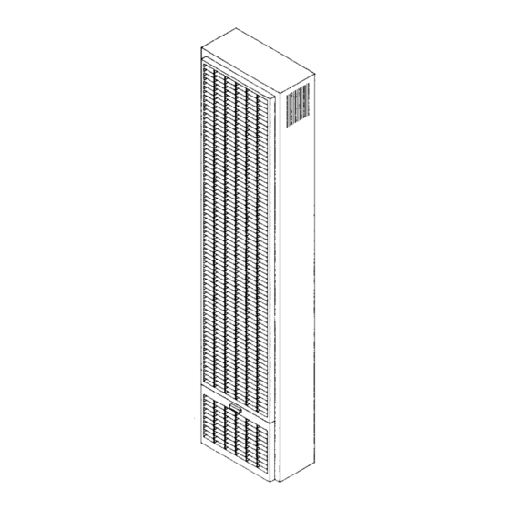
GAS-FIRED TOP VENT
GRAVITY WALL FURNACE
READ THIS OWNERS MANUAL
CAREFULLY
BEFORE YOU INSTALL
YOUR NEW IMPROVED
EFFICIENCY
WILLIAMS
WALL FURNACE
WARNING:
If the
information
in this|
manual is not followed exactly, a fire or ex-
1
plosion
may
result
causing
property
damage, personal injury or loss of life.
--
Do not store or use gasoline or other
flammable
vapors and liquids in the
vicinity of this or any other appliance.
--
WHAT TO DO IF YOU SMELL GAS
• Open all windows.
• Do not try to light any appliance.
• Do not touch any electrical switch; do
not use any phone in your building.
• Extinguish any open flame.
• Immediately
call your gas supplier
from a neighbor's phone. Follow the
gas supplier's instruction.
• If you cannot reach your gas supplier,
call the fire department.
Installation and service must be per-
formed by a qualified installer, service
agency or the gas supplier.
WARNING:
Improper
installation,
adjust-
ment, alteration,
service or maintenance
can cause
injury
or property
damage.
Refer to this manual.
For assistance
or
additional
information
consult a qualified
installer,
service
agency
or
the
gas
supplier.
WARNING:
Do not install any of these fur-
naces
(Natural
or L.R
Gas)
in mobile
homes, trailers,
or recreational
vehicles.
Williams Furnace Co., 225 Acacia St., Colton, CA 92324 U.S.A
PRINTED IN US,A.
5/97
P322085
Advertisement
Table of Contents

Related Manuals for Williams 2509621


Summary of Contents for Williams 2509621
- Page 1 Do not install any of these fur- (0-2000 FT, BASIC ALTITUDE) naces (Natural or L.R Gas) in mobile OR BECOMES 3529612 homes, trailers, or recreational vehicles. (2000-4000 FT. HIGH ALTITUDE) Williams Furnace Co., 225 Acacia St., Colton, CA 92324 U.S.A PRINTED IN US,A. 5/97 P322085...
- Page 2 Contents Williams Installation Policy ...... Surface Mount Installation ...... Introduction ........Vent Installation ......Basic Description ......Mount The Furnace ......Helpful Installation Information ....Gas Supply and Piping ...... 14-15 Safety Rules ......... Thermostat Installation ...... 15-16 Unpack Your Furnace ......
-
Page 3: Introduction
This was done to assure you of receiving the best value and most reliable appliance of its type available today. We are confident that your Williams furnace can provide you years of low cost, efficient, heating comfort. Thank you for purchasing a Williams furnace. -
Page 4: Safety Rules
Safety Rules WARNING umn. The maximum inlet gas supply pressure is 13" water column. READ THESE RULES AND THE INSTRUCTIONS CAREFULLY. FAILURE TO FOLLOW THESE ANY SAFETY SCREEN, GUARD OR PARTS RE- RULES AND INSTRUCTIONS COULD CAUSE A MOVED FOR SERVICING AN APPLIANCE MUST BE MALFUNCTION OF THE FURNACE. -
Page 5: Unpack Your Furnace
Pipe and fittings to make connections to furnace. A type "BW" gas vent kit for vertical venting such as a WILLIAMS Oval Vent Kit 9901. Pipe Joint Compound resistant to L.R gases. Extra lengths of double-wall vent pipe may be needed, *Electrical wiring supplies as needed. - Page 6 Installing Your Wall Furnace The following steps are all needed for proper installation All of CHECKS AND ADJUSTMENTS in the Start-Up and safe operation of your furnace. If you have any doubts Procedure on page 17 are vital to the proper and safe as to any requirements, check with local authorities.
-
Page 7: Combustion & Ventilation Air
Combustion & Ventilation WARNING WARNING DANGER OF ILLNESS DANGER OF PROPERTY DAMAGE, BODILY INJURY OR DEATH BODILY INJURY OR DEATH THE FURNACE AND ANY OTHER FUEL BURNING EVEN WHEN HOUSE MEETS REQUIREMENTS APPLIANCE MUST BE PROVIDED WITH ENOUGH FOR UNCONFINED SPACE WITH ADEQUATE AIR FRESH AIR FOR PROPER COMBUSTION INFILTRATION IT IS RECOMMENDED... - Page 8 Combustion & Ventilation Air (Con't) To determine if infiltration air is adequate, perform the Provide an opening(s) having a total free area of 1 sq. following checks: inch per 4000 Btuh of the total of all appliances. The required area is shown in Fig. 7, page 9. 1.
- Page 9 Combustion & Ventilation Air (Con't) A. All Air From Inside Building: outdoors or spaces open to outdoors such as attic or crawl spaces. If the confined space adjoins an unconfined space as defined in EXAMPLE 1, provide two permanent openings, Provide two permanent openings, one within 12 inches of one within 12 inches of the top and one within 12 inches top, one within 12 inches of bottom of room connecting...
- Page 10 Recessed Mount Installation NOTE: rear outlet plasterground at the same time you install the Model Series 25096 and 35096. The maximum recess header plate. For existing construction, make necessary cutout and install the plasterground just before you install depth, from rear of furnace forward is 41/=''. the furnace.
- Page 11 Recessed Mount Installation (Con't) CEILING PLATE SPACERS CLOSE OFF STUD SPACE RECESSED MOUNT 14 3/8 PLA'flE EXISllNG STUD CEILING PLATE SPACERS NAILED IN BE'nNEEN CEILING NEW STUD PLATES OR ACROSS FACE IF ACCESSIBLE _S_NG S'PJD -_ [ I I BLOCKS •.-- 14--3/8"...
-
Page 12: Vent Installation
Surface Mount Installation Vent Installation (Con't) Type B/W gas vent shall extend from the header plate The use of optional Free Standing Kit No. 4901 allows fur- of the vented wall furnace to a point above the highest nace to be mounted on the surface of a wall. See detailed ceiling plate within a stud space through which the vent instructions packed with kit. -
Page 13: Mount Furnace
Mount The Furnace URING FURNACE POSITION FURNACE LEGS NEAR FLOOR PLATE BOTTOM NAIL FURNACE OF FURNACE LEG TO STUD OR B/W VENT (SEE DETAIL BELOW) FLOiR PLATE MODELS ANGLE 2509612 2509622 3509612 3509622 _FLOOR PLATE 2509611 2509621 IMPORTANT 3509611 AVOID NAILING THE LEGS SO TIGHTLY THAT IT 3509621 DISTURBS THE INNER FURNACE CASINGS. -
Page 14: Gas Supply And Piping
L.R Gas. See page 17 for operation above 2000 feet altitude. FITTING_ R_SER Orifice change may be required to suit gas supplied. PIPED Check with your WILLIAMS service department. i76 2 mini +-=NIPPLE mINIMUM r_ANUAL SHUT OFF SUPPLY ORIFICE SIZES <--- CAP... -
Page 15: Thermostat Installation
Gas Supply and Piping (Con't) CHECKING THE GAS PIPING GAS PIPE SIZES Test all piping for leaks. When checking gas piping to the furnace with gas pressure at less than 1/2 PSI, shut off NATURAL GAS manual gas valve for the furnace, if gas piping is to be PiPE CAPACITY - BTU PER HOUR checked with the pressure at or above 1/2PSI, the furnace... -
Page 16: Thermostat Installation
Connect thermostat wire, previously run to burner com- partment from thermostat, to control valve as shown in Fig. 20. GENERATOR THERMOSTAT GENERATOR THERMOSTAT LIMIT SWITCH RED-_, _--WHITE BLUE KNOB GREEN KNOB WILLIAMS "_ WILLIAMS P295000A (OR) LIMIT SWITCH P172100A (OR) P295001A P172200A --16--... -
Page 17: Operating Your Furnace
Any major changes in the flow must be made the input shown on the rating plate of the furnace. For by changing the size of the burner orifice. Check with your elevations above 2000 feet, the measured input must not WILLIAMS service department for proper orifice sizing. n17--... - Page 18 AND SHUTDOWN equipped). The heated air comes out the front panel louvers. All models listed above are equipped with a Williams gas control valve part number P322051; P322052 (see page 3. When the built-in sensing bulb is sufficiently heated 19) or part number P295100A; P295101A (see page 20).
-
Page 19: To Turn Off Gas To Appliance
FOR YOUR SAFETY, READ BEFORE LIGHTING WILLIAMS GAS CONTROL VALVE P322051 & P322052 I WARNING: If you do not follow these Instructions exactly, a firs or explosion may result causing property damage, personal injury or loss of life. This appliance... - Page 20 FOR YOUR SAFETY, READ BEFORE LIGHTING WILLIAMS GAS CONTROL VALVE P295100A & P295101A I WARNING: If you do not follow these instructions exactly, a fire or explosion may result causing property damage, personal injury or loss of life. This appliance...
- Page 21 The furnace operates like this: 1. Thermostat turns on the main burner. All models listed above are equipped with a Williams gas control valve part number P172100A; P172200A (see 2. Heat builds up in the furnace and starts the fan (if page 22) or part number P295000A;...
- Page 22 FOR YOUR SAFETY, READ BEFORE LIGHTING WILLIAMS GAS CONTROL VALVE P172100A & P172200A WARNING: If you do not follow these instructions exactly, a fire or explosion may result causing property damage, personal Injury or loss of life. • If you cannot...
- Page 23 FOR YOUR SAFETY, READ BEFORE LIGHTING WILLIAMS GAS CONTROL VALVE P295000A & P295001A I WARNING: If you do not follow these instructions exactly, a fire or explosion may result causing property damage, personal injury or loss of life. • If you cannot...
-
Page 24: How To Care For Your Furnace
How To Care For Your Furnace BURNER FLAME WARNING DANGER OF BODILY INJURY OR DEATH Start the furnace and let it operate about 10 minutes then look at the burner flame. Flames should be soft TURN OFF ELECTRIC POWER SUPPLY AT DIS- and blue, see Fig. - Page 25 How To Care For Your Furnace (ton't) WARNING in the burRer area will occur each heating season. It is necessary to clean this area regularly. Use a vacuum cleaner with a narrow attachment to reach small areas. MAKE SURE GAS SUPPLY IS OFF BEFORE Be careful in and around the pilot.
- Page 26 TROUBLE SHOOTING WILLIAMS GAS-FIRED VENT GRAVITY WALL FURNACE SYMPTOM POSSIBLE CAUSES CORRECTIVE ACTION 1. Pilot will not stay lit after A. Thermocouple Check pilot flame - must impinge on thermocouple carefully following generator producing in- or generator. Be sure thermocouple or generator is lighting instructions.
- Page 27 TROUBLE SHOOTING WILLIAMS GAS-FIRED VENT GRAVITY WALL FURNACE CORRECTIVE ACTION SYMPTOM POSSIBLE CAUSES Check thermostat location - should not be in the C. Thermostat location. 3. Furnace operates but turns "Off" before room (Wall thermostat model.) path of warm air discharge from furnace, near a lamp, or above a TM.
- Page 28 WILLIAMS GAS-FIRED TOP VENT GRAVITY WALL FURNACE REPLACEMENT PARTS LIST FOR MODELS 2509611; 2509612; 2509621; 2509622 3509611; 3509612; 3509621; 3509622 REF. PART DESCRIPTION 4915 FACE PANEL 9C155 FRONT HEAT SHIELD 9D52 COMBUSTION CHAMBER ASSY.- 2509611; 2509612; 2509621; 2509622 9D54 COMBUSTION CHAMBER ASSY.
- Page 29 WILLIAMS GAS-FIRED TOP VENT GRAVITY WALL FURNACE REPLACEMENT PARTS MODELS 2509611; 2509612; 2509621; 2509622 3509611; 3509612; 3509621; 3509622 ONLY MANUFACTURER'S AUTHORIZED PARTS =,,_ ip,lo.,,e3 --29--...
-
Page 30: Replacement Parts
WILLIAMS GAS-FIRED TOP VENT GRAVITY WALL FURNACE CONTROL ASSEMBLY REPLACEMENT PARTS LIST FOR MODELS - 2509611; 2509612; 2509621; 2509622 3509611; 3509612; 3509621; 3509622 REF. PART DESCRIPTION 00000000 _LO u3 LO Cxl r,o 9Ct05 T-BURNER (FORMED STEEL, NAT. GAS ONLY) P025600... - Page 31 WILLIAMS GAS-FIRED TOP VENT GRAVITY WALL FURNACE REPLACEMENT PARTS FOR MODELS 2509611; 2509612: 2509621; 2509822; 3509811; 3509612; 3509621; 3509622 FOR REPLACEMENT PARTS LISTING SEE PAGE 50 NAT. GAS CONTROL ASSEMBLY L.P. CONTROL ASSEMBLY...
- Page 32 WILLIAMS GAS - FIRED TOP VENT GRAVITY WALL FURNACE REPLACEMENT PARTS LIST FOR MODELS - 5009611; 5009612; 5009621 ; 5009622 REF. PART DESCRIPTION 4.915 FACE PANEL (2 REQUIRED) 9C155 FRONT HEAT SHIELD (2 REQUIRED) 9A277 CARRYOVER SHELL 9D65 CHAMBER ASSE]_BLY (FRONT)
- Page 33 WILLIAMS GAS FIRED TOP VENT GRAVITY WALL FURNACE REPLACEMENT PARTS FOR MODELS 5009611; 5009612; 5009621; 500962? © ONLY MANUFACTURER'S AUTHORIZED PARTS ,_,_._ IF.t{w-€} --33--...
- Page 34 WILLIAMS GAS-FIRED TOP VENT GRAVITY WALL FURNACE CONTROL ASSEMBLY REPLACEMENT PARTS LIST FOR MODELS - 5009611; 5009612; 5009621; 5009622 _O!LO REF. PART DESCRIPTION u-)u-)u3 u-) 9C105 T-BURNER (FORMED STEEL.NAT. GAS ONLY),2 REQUIRED. P025600 BURNER (CAST IRON), 2 REQUIRED. P043800 GENERATOR...
- Page 35 WILLIAMS GAS-FIRED TOP VENT GRAVITY WALL FURNACE REPLACEMENT PARTS FOR MODELS - 5009611; 5009612: 5009621; 5009622 FOR PARTS LISTING, SEE PAGE 54 NAT. GAS CONTROL ASSEMBLY L.P. GAS CONTROL ASSEMBLY USE ONLY MANUI:'ACTURER*S AUTHORIZED PART5 LIr/oo-ol 135--...
- Page 36 INSTALLATION INSTRUCTIONS 2901 BLOWER ACCESSORY KIT Drill 1/8 inch diameter hole in each side of NOTE: All electrical work must conform to your local STEP 8. codes and ordinances or in their absence, with cur- the furnace face panel through the holes on rant National Electrical Code, ANSI/NFPA 70.
- Page 37 INSTALLATION INSTRUCTIONS REF. ;'ART NO. DESCRIPTION FIG. B. BLOWER ACCESSORY KIT NO. 2901 P013200 Screw- # 8x3/8SheetMetal(8) Required Blower G rille 5"t_TCH },ITR P093200 Screw-#Bx3/8 S heetMetal(2)Required P1410C0 Screw-#10xl/2 S heetMetal(1)Required P320911A FanSwitch- 2 Speed " 1r5v 6_,4z "q" WireBridle P3,?.G912 I HOT NEUT I...
- Page 38 Service Record DATE MAINTENANCE PERFORMED COMPONENTS REQUIRED --38 D...
- Page 39 Notes --39--...
- Page 40 All parts listed herein may be ordered from your equip- information: ment supplier. 1. MODEL NUMBER The Model Number of your Williams wall furnace will be 2. MFG. DATE CODE found on the rating plate near gaB valve, inside control 3. PART NUMBER compartment.