
Related Manuals for Fluke ESA601


Summary of Contents for Fluke ESA601
- Page 1 ESA601 Electrical Safety Analyzer Operators Manual November 2004, Rev. 1, 12/05 © 2004-2005 Fluke Corporation, All rights reserved. All product names are trademarks of their respective companies.
- Page 2 Fluke Biomedical. This warranty does not apply if the product has been damaged by accident or misuse or as the result of service or modification by other than Fluke Biomedical. IN NO EVENT SHALL FLUKE BIOMEDICAL BE LIABLE FOR CONSEQUENTIAL DAMAGES.
-
Page 3: Unpacking And Inspection
Copyright Release Fluke Biomedical agrees to a limited copyright release that allows you to reproduce manuals and other printed materials for use in service training programs and other technical publications. If you would like other reproductions or distributions, submit a written request to Fluke Biomedical. - Page 4 No responsibility is assumed by Fluke Biomedical for the use or reliability of software or equipment that is not supplied by Fluke Biomedical, or by its affiliated dealers.
-
Page 5: Table Of Contents
Table of Contents Chapter Title Page Standards and Safety....................vi Applicable Testing Standards ................vi USA Class A .....................vi Canadian Department of Communications Class A........vi EC Directive 89/336/EEC Electromagnetic Compatibility ......vi Emissions - Class A ..................vi Immunity ....................vi EC Directive 73/23/EEC Low Voltage ............vii User Safety ....................vii Safety Considerations ..................vii General Information ................ - Page 6 ESA601 Operators Manual Testing Devices ................... 4-1 Connecting the Device Under Test ..............4-3 Selecting the Test Load..................4-3 Testing Device Types ..................4-4 Permanently Wired Devices ................4-4 Portable Devices Located in Isolated Power Systems........4-4 Three-Phase Portable Devices ...............4-4 Local Control ..................5-1 Mode Control.....................5-3 Function Selection .....................5-3 Performing Electrical-Safety Tests ..............5-9...
- Page 7 List of Tables Table Title Page 1-1. ESA601 Electrical Safety Analyzer Versions ............1-4 1-2. Top and Side Panel Features .................. 1-7 1-3. Back Panel Connectors ..................1-10 5-1. Function Selection Switch Positions ..............5-3 5-2. Active Switch Settings for Selected Tests.............. 5-7 6-1.
- Page 8 ESA601 Operators Manual...
- Page 9 List of Figures Figure Title Page 1-1. Top and Side Panel Views of the ESA601............. 1-6 1-2. Back Panel View of the ESA601 (IEC) ..............1-9 1-3. Back Panel View of ESA601 (AAMI) ..............1-9 4-1. ESA601 Connected to a Device Under Test ............4-3 5-1.
-
Page 10: Standards And Safety
Operators Manual Standards and Safety Applicable Testing Standards Fluke Biomedical's ESA601 Electrical Safety Analyzer (hereafter called the ESA601) has been tested and certified to US and Canadian standards by CSA. The unit conforms to IEC/EN 61010- 1 2nd Edition and IEC/EN 61326 and bears the CE mark. -
Page 11: Ec Directive 73/23/Eec Low Voltage
EC Directive 73/23/EEC Low Voltage User Safety The system has been type tested and found to meet the requirements of EC Directive 73/23/EEC for Low Voltage. Verification of compliance was conducted to the limits and methods of the following: EN 61010-1 (2001) 2 Edition “Safety Requirements for Electrical Equipment for Measurement, Control and Laboratory Use, Part 1: General requirements”... - Page 12 ESA601 Operators Manual WXWarning. Read before using the Analyzer To avoid possible electrical shock or personal injury, follow these guidelines: ⇒ Do not use the ESA601 in any manner not specified in this manual. ⇒ Before connecting or disconnecting a DUT to the ESA601, the FUNCTION-SELECTION KNOB should be set to the OFF position.
-
Page 13: General Information
Chapter 1 General Information Title Page Introduction to the ESA601 ................1-3 ESA601 Package Contents ................1-3 ESA601 Electrical Safety Analyzer .............. 1-3 Standard Accessories..................1-4 Optional Accessories ..................1-4 Unpacking the ESA601 ................. 1-5 Storage and Maintenance ................1-5 ESA Characteristics ................... - Page 14 ESA602 Operators Manual...
-
Page 15: Introduction To The Esa601
General Information Introduction to the ESA601 Introduction to the ESA601 The Fluke Biomedical Electrical Safety Analyzer (hereafter called the ESA601 ESA601 is a full-featured, low-cost, compact analyzer, designed to verify the electrical safety of medical devices. The satisfies international (IEC 601-1,VDE) and domestic ESA601 (ANSI/AAMI ES1) electrical-safety standards. -
Page 16: Standard Accessories
ESA602 Operators Manual Table 1-1. ESA601 Electrical Safety Analyzer Versions DUT Outlet Detachable Language Version Model Number (Test Recepticle) Power Cord Overlay Australian Australia/New Zealand Australian English 1 ESA601-AUS AS/NZ 3112-1993 Schuko CEE7 European English 1 ESA601-SHK (International) French Schuko CEE7 European French ESA601-FRA... -
Page 17: Unpacking The Esa601
If any physical damage is apparent, please call Fluke Biomedical for assistance between 8:00 AM and 5:00 PM, Pacific Standard Time, Monday through Friday, except holidays: (800)-648-7952 (in the U.S.) or (775) 883-3400. -
Page 18: Esa Characteristics
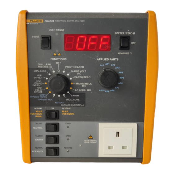
ESA602 Operators Manual ESA Characteristics The following two sections will help familiarize you with the ESA601 Safety Analyzer’s controls and features. Top and Side Panels Table 1-2 lists and describes the controls on the top and side panels that are called out in Figure 1. -
Page 19: Top And Side Panel Features
General Information ESA Characteristics Table 1-2. Top and Side Panel Features Name Description An equipment outlet, specific to the version of the TEST RECEPTACLE instrument, that provides a DUT connection: AS 3112-1993 (Australia); BS 1363A (English – United Kingdom); NEMA 5-15R (English – United States);... - Page 20 ESA602 Operators Manual Figure 1-2. Top and Side Panel Features (cont.) Name Description A LED to the upper right of the , which OVER RANGE STATUS INDICATOR PRINT SWITCH illuminates with a solid red light ( ) if the OVER RANGE input exceeds measurement range.
-
Page 21: Back Panel
General Information ESA Characteristics Figure 1-2. Top and Side Panel Features (cont.) Name Description A slide switch, which permits the selection of either LOAD SELECTION SWITCH the ANSI / AAMI ES1 or the IEC 60601-1 patient load RS-232 Port A serial interface, which, in Remote Mode, enables remote operation of the ESA601, and provides a download port for processor firmware. -
Page 22: Date Of Manufacture
ESA602 Operators Manual Table 1-3. Back Panel Connectors Label Meaning RA or R, AP1 Right arm, applied part 1 RL or N, AP2 Right leg, applied part 2 LA or L, AP3 Left arm, applied part 3 LL or F, AP4 Left leg, applied part 4 V 1 , V 2 , V 3 , V 4 , V 5 , and V 6 V Leads (U.S. -
Page 23: Setting Up The Esa601
Chapter 2 Setting Up the ESA601 Title Page Powering Up the ESA601.................. 2-3 Support....................... 2-3... - Page 24 ESA602 Operators Manual...
-
Page 25: Powering Up The Esa601
Support After power-up and connection, if the new ESA601 system fails to start or to operate successfully, please contact Fluke Biomedical immediately. The Technical Assistance Center is open between 8:00 AM and 5:00 PM, Pacific Standard Time, Monday through Friday, except holidays. - Page 26 ESA602 Operators Manual...
-
Page 27: Using The Printer
Chapter 3 Using the Printer Title Page Selecting Language Options ................3-3 Selecting the Printer Output................3-3 Printing Electrical Safety Test Results .............. 3-3... - Page 28 ESA602 Operators Manual...
-
Page 29: Selecting Language Options
Using the Printer Selecting Language Options Selecting Language Options Five language options support the eight available factory-set versions of the ESA601 that are unique combinations of types of DUT outlet (test receptacle), detachable line cord, and overlay language: English with IEC nomenclature (“E”) English with AAMI nomenclature (“E-US,”... - Page 30 ESA602 Operators Manual For procedures on how to perform a Protective-Earth-Resistance test and print the test results, see “Performing Electrical-Safety Tests” in Chapter 5 of this manual. Note If the is pressed with the set to the PRINT SWITCH FUNCTION SELECTION KNOB position, no printout results.
-
Page 31: Testing Devices
Chapter 4 Testing Devices Title Page Connecting the Device Under Test ..............4-3 Selecting the Test Load..................4-3 Testing Device Types ..................4-4 Permanently Wired Devices ................4-4 Portable Devices Located in Isolated Power Systems........4-4 Three-Phase Portable Devices ............... 4-4... - Page 32 ESA602 Operators Manual...
-
Page 33: Connecting The Device Under Test
Testing Devices Connecting the Device Under Test Connecting the Device Under Test While referring to Figure 4-1, follow the steps below to connect the ESA601 to a device under test (DUT). Whenever connecting or disconnecting a DUT to the ESA601, the should be set to the position. -
Page 34: Testing Device Types
ESA602 Operators Manual Testing Device Types For step-by-step instructions on making electrical safety tests with the ESA601, refer to “Performing Electrical-Safety Tests” in chapter 5 of this manual. Permanently Wired Devices Permanently wired devices can be tested only in an state. -
Page 35: Local Control
Chapter 5 Local Control Title Page Mode Control..................... 5-3 Function Selection ..................... 5-3 Performing Electrical-Safety Tests ..............5-9 Mains-Voltage Test ..................5-9 Protective-Earth-Resistance Test..............5-10 Mains-Insulation-Resistance Test..............5-12 Applied-Parts-Insulation-Resistance Test ............. 5-13 Earth-Leakage-Current Test ................5-14 Enclosure-Leakage-Current Test..............5-16 Patient-Leakage-Current Test................ 5-18 Patient-Auxiliary-Leakage-Current Test ............ - Page 36 ESA602 Operators Manual...
-
Page 37: Mode Control
Local Control Mode Control Mode Control The operation of the ESA601 can be controlled through two separate modes: Local and Remote. The power-up default mode of the ESA601 is Local Mode where functions are selected by manually positioning the . (For the location of FUNCTION SELECTION KNOB , refer to “Unit Characteristics”... - Page 38 ESA602 Operators Manual Table 5-1, Function Selector Switch Positions (cont.) EARTH RES ( ) or GROUND WIRE RES ( ) Measures the resistance between the RED Protective-Earth Resistance input connection and Equipment Outlet Earth (equivalent to the GREEN signal connection). DUT power is off.
- Page 39 Local Control Function Selection Table 5-1, Function Selector Switch Positions (cont.) ENCLOSURE or CHASSIS Measures the RMS current flowing in the Enclosure-Leakage Current tester’s measurement device connected between the RED signal connection and Mains Earth. DUT power is on. NOTE 1: All applied-parts connectors are grounded for this test when you select the ALL position with the Applied-Parts-Selection Knob.
- Page 40 ESA602 Operators Manual Table 5-1, Function Selector Switch Positions (cont.) VDE: EQUIV DEVICE Places the tester’s measurement-device circuit VDE: Equivalent-Device-Leakage Current in series with a current-limited M.A.P. voltage that is connected between [Equipment Outlet L1 shorted to Equipment Outlet L2 and disconnected from Mains power] and [Equipment Outlet Earth, Mains Earth, the RED signal connection, and all applied-parts...
-
Page 41: Active Switch Settings For Selected Tests
Local Control Function Selection Table 5-2. Active Switch Settings for Selected Tests ACTIVE SWITCH SETTINGS for the TEST SELECTED FUNCTION APPLIED- M.A.P./VDE NEUTRAL EARTH POLARITY OHMS SELECTED SELECTOR PARTS EQUIV/ SWITCH SWITCH SWITCH FUNCTION TEST KNOB SELECTOR INSUL SWITCH KNOB SWITCH (momentary) (momentary) - Page 42 ESA602 Operators Manual Table 5-2, Active Switch Settings for Selected Tests (cont.) ACTIVE SWITCH SETTINGS for the TEST SELECTED FUNCTION APPLIED- M.A.P./VDE NEUTRAL EARTH POLARITY OHMS SELECTE SELECTOR PARTS EQUIV/ SWITCH SWITCH SWITCH FUNCTION D TEST KNOB SELECTOR INSUL SWITCH KNOB SWITCH (momentary)
-
Page 43: Performing Electrical-Safety Tests
Local Control Performing Electrical-Safety Tests Performing Electrical-Safety Tests The following section contains test-principle diagrams (with notes on switches and functions) and step-by-step instructions for performing the electrical-safety tests that are available by positioning the ESA601 FUNCTION SELECTION KNOB Note The following descriptions refer to holding down the to print PRINT SWITCH results. -
Page 44: Protective-Earth-Resistance Test
ESA602 Operators Manual Protective-Earth-Resistance Test The Protective-Earth-Resistance test measures the impedance between the outlet PE terminal of the ESA601and exposed conductive parts of the DUT that are connected to the DUT’s Protective Earth. Figure 5-1 shows the electrical connections between the ESA601 and the DUT. - Page 45 Local Control Performing Electrical-Safety Tests When the Ω ( Ω) function is selected initially, and the EARTH RES GROUND WIRE RES is set to the default (OFF) position, the ESA601 display OHMS FUNCTION SWITCH indicates PE (Protective Earth), and the null offset value is equal to the last null offset value.
-
Page 46: Mains-Insulation-Resistance Test
ESA602 Operators Manual Mains-Insulation-Resistance Test The Mains-Insulation-Resistance test measures the insulation resistance (at 500 V DC) between L1 and L2 and the DUT’S Protective Earth. Figure 5-2 shows the electrical connections between the ESA601 and the DUT. The table below the diagram indicates the position of switches in the diagram during the test. -
Page 47: Applied-Parts-Insulation-Resistance Test
Local Control Performing Electrical-Safety Tests Applied-Parts-Insulation-Resistance Test The Applied-Parts-Insulation-Resistance test measures the insulation resistance (at 500 V DC) between all applied-parts connections and the DUT’S Protective Earth. Figure 5-3 shows the electrical connections between the ESA601 and the DUT. The table below the diagram indicates the position of switches in the diagram during the test. -
Page 48: Earth-Leakage-Current Test
ESA602 Operators Manual Earth-Leakage-Current Test The Earth-Leakage-Current Test measures the current flowing in the DUT’s Protective Earth. Figure 5-4 shows the electrical connections between the ESA601 and the DUT. The table below the diagram indicates the position of switches in the diagram during the test. - Page 49 Local Control Performing Electrical-Safety Tests Action 1. Position the FUNCTION SELECTION KNOB EARTH GROUND WIRE 2. Position the 1 (if applicable). APPLIED PARTS SELECTION KNOB Note For type-BF and type-CF equipment, perform the measurement with the selection knob both open (by selecting any selection except APPLIED PARTS , in the above case RA or AP1) and closed (by selecting 3.
-
Page 50: Enclosure-Leakage-Current Test
ESA602 Operators Manual Enclosure-Leakage-Current Test The Enclosure-Leakage-Current test measures the current flowing from the RED terminal . Figure 5-5 shows the electrical connections between the ESA601 and the MAINS PE DUT. The table below the diagram indicates the position of switches in the diagram during the test. - Page 51 Local Control Performing Electrical-Safety Tests Action 1. Position the FUNCTION SELECTION KNOB ENCLOSURE CHASSIS 2. Set the 1 (if applicable). APPLIED PARTS SELECTION KNOB Note For type-BF and type-CF equipment, perform the measurement with the selection knob both open (by selecting any selection except APPLIED PARTS , in the above case 1) and closed (by selecting...
-
Page 52: Patient-Leakage-Current Test
ESA602 Operators Manual Patient-Leakage-Current Test The Patient-Leakage-Current test measures the current flowing between a selected applied part, or applied parts, and the Mains PE. Figure 5-6 shows the electrical connections between the ESA601 and the DUT. The table below the diagram indicates the position of switches in the diagram during the test. - Page 53 Local Control Performing Electrical-Safety Tests Note The Patient-Leakage-Current test is applicable only to DUTs with applied parts. Action 1. Position the FUNCTION SELECTION KNOB PATIENT LEAD TO GROUND 2. Position the APPLIED PARTS SELECTION KNOB 3. Set the NEUTRAL SWITCH CLOSED 4.
-
Page 54: Patient-Auxiliary-Leakage-Current Test
ESA602 Operators Manual Patient-Auxiliary-Leakage-Current Test The Patient-Auxiliary-Leakage-Current test measures the current between a selected applied part and all others. Figure 5-7 shows the electrical connections between the ESA601 and the DUT. The table below the diagram indicates the position of switches in the diagram during the test. - Page 55 Local Control Performing Electrical-Safety Tests Note The Patient-Auxiliary-Leakage-Current test is applicable only to DUTs with applied parts. Action 1. Position the FUNCTION SELECTION KNOB PATIENT AUX LEAD TO LEADS 2. Position the APPLIED PARTS SELECTION KNOB 3. Set the NEUTRAL SWITCH CLOSED 4.
-
Page 56: Mains-On-Applied-Parts-Leakage-Current Test
ESA602 Operators Manual Mains-On-Applied-Parts-Leakage-Current Test The Mains-On-Applied-Parts-Leakage-Current test measures the current that flows in response to an isolated AC voltage applied between a selected applied part, or ALL applied parts, and Earth (and any conductive part connected to the RED terminal). Figure 5-7 shows the electrical connections between the ESA601 and the DUT. - Page 57 Local Control Performing Electrical-Safety Tests Note The Mains-on-Applied-Parts-Leakage-Current test is applicable only to DUTs with applied parts. Action 1. Position the FUNCTION SELECTION KNOB MAINS APPLIED PARTS LEAD ISOLATION 2. Position the APPLIED PARTS SELECTION KNOB 3. Set the , and wait for the analyzer to switch to normal. POLARITY SWITCH NORMAL 4.
-
Page 58: Vde: Equivalent-Device-Leakage-Current Test
ESA602 Operators Manual VDE: Equivalent-Device-Leakage-Current Test The VDE:Equivalent-Device-Leakage-Current test measures the current that flows between the shorted Mains terminals (L1 and L2) of the DUT to the PE, applied parts, and exposed conductive parts of the DUT (connected to the RED signal connection) in response to an isolated AC voltage source with a magnitude of at least 110 % of Mains voltage. - Page 59 Local Control Performing Electrical-Safety Tests Action 1. Connect the banana plug end of the RED test lead into the RED signal jack, and the probe end of the RED test lead to the DUT enclosure; connect the DUT applied parts to the applied-parts jacks on the ESA601;...
-
Page 60: Vde: Equivalent-Patient-Leakage-Current Test
ESA602 Operators Manual VDE: Equivalent-Patient-Leakage-Current Test The VDE:Equivalent-Patient-Leakage-Current test measures the current that flows between the applied-parts terminals of the DUT to the PE, Mains terminals (L1 and L2), and exposed conductive parts of the DUT (connected to RED signal connection) in response to an isolated AC voltage source with a magnitude of at least 110 % of Mains voltage. - Page 61 Local Control Performing Electrical-Safety Tests Action 1. Connect the banana plug end of the RED test lead into the RED signal jack, and the probe end of the RED test lead to the DUT enclosure; connect the DUT applied parts to the applied-parts jacks on the ESA601;...
-
Page 62: Vde: Differential-Leakage-Current Test
ESA602 Operators Manual VDE: Differential-Leakage-Current Test The VDE: Differential-Leakage-Current test measures the magnitudes of the differential current flowing in the Equipment Outlet L1 and L2 circuits. Figure 5-11 shows the electrical connections between the ESA601 and the DUT. The reading is taken after selecting this function. -
Page 63: Dual-Lead-Leakage-Current Test
Local Control Performing Electrical-Safety Tests Dual-Lead-Leakage-Current Test The Dual-Lead-Leakage-Current test measures the current flowing from the RED signal connection to the BLACK signal connection. Figure 5-12 shows the electrical connections between the ESA601 and the DUT. DUT power is on. The table below the diagram indicates the position of switches in the diagram during the test. -
Page 64: Dual-Lead-Voltage Test
ESA602 Operators Manual Note The followings steps can be performed if desired. 7. Set the NEUTRAL SWITCH OPEN 8. After the meter settles, read the display, and/or press the to print the PRINT SWITCH reading. 9. Set the NEUTRAL SWITCH CLOSED 10. - Page 65 Local Control Performing Electrical-Safety Tests Action 1. Connect the RED and BLACK test leads to the RED and BLACK test jacks on the ESA601. 2. Position the FUNCTION SELECTION KNOB DUAL LEAD VOLTAGE 3. Connect the RED test lead to the DUT enclosure; connect the DUT power cord to the test receptacle on the ESA601.
- Page 66 ESA602 Operators Manual 5-32...
-
Page 67: Remote Control
Chapter 6 Remote Control Title Page Using Remote Control ..................6-3 Setup Requirements..................6-3 Ansur ESA601 Plug-In Software Introduction..........6-3 Sending Commands from the Host Computer..........6-4 Remote Control Commands................6-4... - Page 68 ESA602 Operators Manual...
-
Page 69: Using Remote Control
(PN 2238626). Instructions for the application’s setup and use can be found in the Ansur and ESA601 Plug-In Users Manual (Start | Programs | Fluke | Ansur Help | Ansur User Manual or ESA601 Plug-In User Manual). The ESA601 Plug-In and Ansur product line is Windows 2000 and Windows®... -
Page 70: Sending Commands From The Host Computer
ESA602 Operators Manual Sending Commands from the Host Computer 1. Press on the PC keyboard to check communications. The analyzer should ENTER return “?”. 2. Using the terminal-emulation program, type the command “REMOTE”. The analyzer responds with "REMOTE MODE" and switches to the function, that is, turns all Equipment-Outlet power. - Page 71 Remote Control Remote Control Commands Table 6-1. Remote Control Commands (cont.) COMMAND PARAMETERS ACTION Switches to the Enclosure-Leakage-Current test. FUNCT= ENCL_LEAK Switches to the Patient-Leakage-Current test. FUNCT= PAT_LEAK Switches to the Patient-Auxiliary-Leakage-Current test. FUNCT= PAT_ AUX Switches to the Mains-on-Applied-Parts-Leakage-Current test. FUNCT= Switches to the VDE: Equivalent-Device-Leakage-Current test.
- Page 72 ESA602 Operators Manual Table 6-1. Remote Control Commands (cont.) COMMAND PARAMETERS ACTION (no parameters) Reads meter. (Sends data to serial port.) If reading is over range, returns READ_METER “OL.” Reads report (WITH HEADER) for current function. (Sends report to serial (no parameters) REPORT_HDR port.)
-
Page 73: Operator Messages And Service
Chapter 7 Operator Messages and Service Title Page Error Codes ......................7-3 Power-up Error Codes ................... 7-3 Start Up Diagnostic Error Codes ..............7-3 Service ....................... 7-4... - Page 74 ESA602 Operators Manual...
-
Page 75: Error Codes
A power-up error is indicated if the ESA601 has the power LED on, fault LED on, blank display and continuously outputs one of the following codes to the Serial Transmit line. If any of the power-up error codes occur, contact your local Fluke service center to arrange repair of the ESA601. -
Page 76: Service
Operators Manual Service The ESA601 should be calibrated once a year by a qualified technician. It is recommended that the instrument be sent to Fluke for factory calibration and service. Service (Repairs and Calibration): Fluke Customer Service Center 1420 – 75th Street SW... -
Page 77: Appendices
Appendices Appendix Title Page Specifications ...................... A-1 Sample ESA601 Test Printouts ................B-1 Equivalent Report Terms ..................C-1 Abbreviations ...................... D-1... - Page 78 ESA602 Operators Manual...
-
Page 79: A Specifications
Appendix A Specifications General Specifications Operating Voltage Range: Minimum 90 V AC, Maximum 264 V AC. POWER Line Cords and AC Mains Inlet: 16 A or greater, 250 V for Class-1 equipment in cold conditions. Equipment Outlet: 15 A, 250 V for Class-1 equipment in cold conditions for Australian, European, and United States versions. -
Page 80: Performance Specifications
ESA602 Operators Manual Performance Specifications Ranging: Auto LEAKAGE CURRENT MEASUREMENT Configuration: RMS current flowing through the IEC 60601-1 test load or ANSI / AAMI ES1 test load (selectable). Measurement Range: 0 - 8000 A True RMS Display Units: A Display Resolution: 1 A ±1% of reading ( ±2 µA) @ DC and 25 Hz to 1000 Hz †... - Page 81 Appendices Specifications Input/Output Connection Specifications Standard IEC 60320-1 / C20 Mains inlet rated at 16 A and 250 V for MAINS INLET Class-1 equipment in cold conditions Specific to version of instrument: EQUIPMENT OUTLET AS 3112-1993 (Australia) TEST RECEPTACLE BS 1363A (English – United Kingdom) NEMA 5-15R (English –...
- Page 82 ESA602 Operators Manual...
-
Page 83: B Sample Esa601 Test Printouts
The two sample printouts in this appendix are from the two English language versions of the ESA601. Appendix C lists the words used in all the versions of the ESA601. Sample Printout, English 1 Version (ESA601-US/IEC, -UK, -SHK, & -AUS) FLUKE BIOMEDICAL DATE:__________________ LOCATION:______________ DEVICE TYPE:___________... - Page 84 ESA602 Operators Manual MAINS VOLTAGE [V 122.4 PROT. EARTH RESISTANCE [OHM] 1.035 INSUL RESISTANCE [MOHM] L1,L2-CASE 095.6 INSUL RESISTANCE [MOHM] AP-CASE 099.5 EARTH LEAKAGE CUR. [uA] NORM POL, NO EARTH: 0001 NORM POL, NO L2, NO EARTH: 0001 REV POL, NO EARTH: 0001 NORM POL, NO EARTH: All-Earth...
- Page 85 Appendices Sample ESA601 Test Printouts AP7-Earth 4742 AP8-Earth 4740 AP9-Earth 4738 AP10-Earth 4741 REV POL, NO L2: AP1=Earth 4710 REV POL, NO L2, NO EARTH: AP1-Earth 4728 NORM POL, NO L2, NO EARTH: AP1-Earth 4677 NORM POL, NO L2: AP1-Earth 4651 NORM POL: AP1-Earth...
- Page 86 ESA602 Operators Manual NORMAL ISOLATION POL, NORM POL: AP3-Earth 0001 NORMAL ISOLATION POL, NORM POL: AP4-Earth 0001 NORMAL ISOLATION POL, NORM POL: AP5-Earth 0001 NORMAL ISOLATION POL, NORM POL: AP6-Earth 0001 NORMAL ISOLATION POL, NORM POL: AP7-Earth 0001 NORMAL ISOLATION POL, NORM POL: AP8-Earth 0001 NORMAL ISOLATION POL, NORM POL:...
- Page 87 Appendices Sample ESA601 Test Printouts Sample Printout, US-English 2 Version (ESA601-USA) FLUKE BIOMEDICAL DATE:__________________ LOCATION:______________ DEVICE TYPE:___________ MANUFACTURER:__________ SERIAL# :______________ TECHNICIAN:____________ ESA601: Comments: MAINS VOLTAGE [V] 122.4 GROUND WIRE RESISTANCE [OHM] 1.035 INSUL RESISTANCE [MOHM] L1,L2-CASE 095.6 INSUL RESISTANCE [MOHM] LEADS-CASE 099.5...
- Page 88 ESA602 Operators Manual LEAD TO GROUND LEAKAGE CUR [uA] NORM POL: RA-GROUND 4686 NORM POL: All-GROUND 4677 RA-GROUND 4682 RL-GROUND 4686 LA-GROUND 4686 LL-GROUND 4687 V1-GROUND 4688 V2-GROUND 4692 V3-GROUND 4692 V4-GROUND 4690 V5-GROUND 4691 V6-GROUND 4693 REV POL: All-GROUND 4654 RA-GROUND 4684...
- Page 89 Appendices Sample ESA601 Test Printouts REV POL: RA-All 0001 NORM POL, NO GROUND: RA-All 0001 REV POL, NO GROUND: RA-All 0001 REV POL, NO L2, NO GROUND: RA-All 0001 REV POL, NO L2: RA-All 0001 NORM POL, NO L2: RA-All 0001 NORM POL: RA-All...
- Page 90 ESA602 Operators Manual NORMAL ISOLATION POL, NO L2: 0002 REVERSE ISOLATION POL, NO L2: 0002 VDE DIFFERENTIAL CUR [uA] 0016 DUAL LEAD LEAKAGE [uA] NORM POL, NO GROUND: 0217 NORM POL, NO L2, NO GROUND: 0217 REV POL, NO GROUND: 0217 REV POL, NO L2, NO GROUND: 0217...
-
Page 91: Equivalent Report Terms
ITALIAN TERM GERMAN TERM TERM TERM Language selected Language selected Language selected Language selected Language selected “E” “E-US” “F” “I” “D” FLUKE BIOMEDICAL FLUKE BIOMEDICAL FLUKE BIOMEDICAL FLUKE BIOMEDICAL FLUKE BIOMEDICAL DATE DATE DATE DATA DATUM LOCATION LOCATION SERVICE REPARTO... - Page 92 ESA602 Operators Manual Figure C-1. Language Equivalents for Terms on Report Printouts (cont.) ENGLISH IEC ENGLISH AAMI FRENCH TERM ITALIAN TERM GERMAN TERM TERM TERM PROT. EARTH GROUND WIRE RES. DE TERRE DE RES COND. SCHUTZLEITERWID RESISTANCE [OHM] RESISTANCE [OHM] PROT [OHM] PROTEZIONE [OHM] ERSTAND [OHM]...
- Page 93 Appendices Equivalent Report Terms Figure C-1. Language Equivalentsfor Terms on Report Printouts (cont.) ENGLISH IEC ENGLISH AAMI FRENCH TERM ITALIAN TERM GERMAN TERM TERM TERM AP8-All V4-All AP8-Tous PA8-Tutte ANW TEIL 8/Alle AP9-All V5-All AP9-Tous PA9-Tutte ANW TEIL 9/Alle AP10-All V6-All AP10-Tous PA10-Tutte...
- Page 94 ESA602 Operators Manual...
-
Page 95: D Abbreviations
Appendix D Abbreviations Abbreviations ampere AAMI American Association of Medical Instrumentation applied parts clear to send decibel data communication equipment data terminal equipment device under test hertz International Electrotechnical Commission kilohertz left arm light-emitting diode left leg megohm M.A.P. / MAP Mains on applied parts megahertz megohm... - Page 96 ESA602 Operators Manual picofarad part number right arm right leg ready to send serial peripheral interface volt microampere degrees Celsius (centigrade)