Table of Contents
Advertisement
Quick Links
OTRO_ BILT
OPERATOR'S
MANUAL
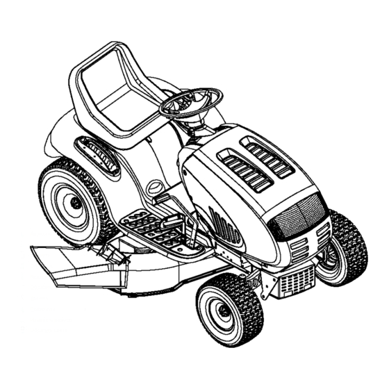
Pedal Drive Lawn Tractor
Model 609
Model Z609H Shown
IMPORTANT:
READ SAFETY
RULES AND INSTRUCTIONS
CAREFULLY
Warning:
This unit is equipped with an internal combustion engine and should not be used on or near any unimproved
forest-cov-
ered, brush-covered
or grass-covered
land unless the engine's exhaust system is equipped with a spark attester
meeting applicable
local or state laws (if any). If a spark arrester is used, it should be maintained
in effective working order by the operator. In the State of
California the above is required by law (Section 4442 of the California
Public Resources Code). Other states may have similar laws.
Federal laws apply on federal lands. A spark arrester for the muffler is available through your nearest engine authorized service dealer
or contact the service department,
P.O. Box 368022 Cleveland, Ohio 44136-9722.
MTD PRODUCTS
INC. P.O. BOX 368022 CLEVELAND,
OHIO 44136-9722
TROY-BILT® is a registered
trademark
owned
by Garden
Way Incorporated
of Troy, New York.
PRINTED IN U.S.A.
FORM NO. 770-10250A
(10/99)
Advertisement
Table of Contents

Related Manuals for Troy-Bilt 609


Summary of Contents for Troy-Bilt 609
- Page 1 Federal laws apply on federal lands. A spark arrester for the muffler is available through your nearest engine authorized service dealer or contact the service department, P.O. Box 368022 Cleveland, Ohio 44136-9722. MTD PRODUCTS INC. P.O. BOX 368022 CLEVELAND, OHIO 44136-9722 TROY-BILT® is a registered trademark owned by Garden Way Incorporated of Troy, New York.
- Page 2 SECTION 1: TABLE OF CONTENTS PAGE FINDING YOUR MODEL NUMBER ............CALLING CUSTOMER SUPPORT ............IMPORTANT SAFE OPERATION PRACTICES..........SAFETY LABLES FOUND ON YOUR UNIT..........SLOPE GAUGE ..............ATTACHMENTS & ACCESSORIES ............TRACTOR SET-UP ..............CONTROLS ................. OPERATION ................ ADJUSTMENTS ..............MAINTENANCE ..............
- Page 3 SECTION 4: IMPORTANT SAFE OPERATION PRACTICES WARNING: THIS SYMBOL POINTS OUT IMPORTANT SAFETY INSTRUCTIONS WHICH, IF NOT FOLLOWED, COULD ENDANGER THE PERSONAL SAFETY AND/OR PROPERTY YOURSELF AND OTHERS. READ AND FOLLOW INSTRUCTIONS IN THIS MANUAL BEFORE ATTEMPTING TO OPERATE YOUR LAWN MOWER. FAILURE TO COMPLY WITH THESE INSTRUCTIONS MAY RESULT IN PERSONAL INJURY.
- Page 4 • Disengage a ll attachment clutches, t horoughly 3. CHILDREN depress the brakepedal, a ndshiftinto neutral Tragic accidents can occur if the operator is not alert to the before a ttempting tostart e ngine. presence of children. Children are often attracted to the •...
- Page 5 • Keep allnuts, b olts andscrews t ight t o besurethe Do notchange the engine governor settings o r equipment isinsafe working condition. overspeed the engine. E xcessive engine speeds aredangerous. • Nevertamper w ith safetydevices. Checktheir properoperation regularly. Use all guardsas Observe properdisposal lawsand regulations.
- Page 6 USE THIS PAGE AS A GUIDE TO DETERMINE SLOPES WHERE YOU MAY NOT OPERATE SAFELY. SIGHT AND HOLD THIS LEVEL WITH A VERTICAL TREE A POWER POLE A CORNER OF A BUILDING _ _ _ _ _! OR A FENCE POST "'""...
- Page 7 SECTION 5: ATTACHMENTS & ACCESSORIES MODEL NUMBER DESCRIPTION OEM-190-601 FastAttach" Twin Bagger Grass Collector (For 42-inch Decks Only) OEM-190-602 FastAttach" Twin Bagger Grass Collector (For 46-inch Decks Only) OEM-190-112 Mulch Kit (For 42-inch Decks Only) OEM-190-118 Mulch Kit (For 46-inch Decks Only) OEM-190-603 FastAttach"...
- Page 8 SECTION 7: CONTROLS NOTE: Steering Wheel not shown for clarity. Figure 3 Brake Pedal Ignition Switch Throttle Control Lever Parking Brake Button Shift Lever Choke Control (if so equipped) Systems Indicator Monitor Seat Adjustment Lever Uft Lever Cup Holder Cruise Control Button PTO (Power Take-Off) Lever* Drive Pedal PTO (Power Take-Off) Knob*...
- Page 9 IGNITION SWITCH CHOKE CONTROL To start the engine, insert key into the ignition switch On some units, moving and turn clockwise to the START position. Release throttle lever key to the ON position once engine has fired. See forward activates the engine's choke control.
- Page 10 BRAKE PEDAL ELECTRIC (POWER TAKE-OFF) KNOB k BRAKE _ To engage the power to the cutting deck other attachments, pull outward on the PTO knob. Push the PTO knob inward to disengage the power to the attachments. The brake pedal is located on the right front side of the tractor above the drive pedal along the running NOTE: The PTO knob must be in the disengaged...
- Page 11 SHIFT LEVER CRUISE CONTROL BUTTON The shift lever is located The cruise control button is located on het cto d s 0ane tot e ; r, on the left side fender three ignition switch. Push the cruise control positions, FORWARD, button while traveling forward...
- Page 12 SETTING THE CUTTING HEIGHT STOPPING THE ENGINE • Place the PTO lever, or PTO knob in the Select the height position of the cutting deck by placing the deck lift lever in any of the six different disengaged (OFF) position cutting height notches on the right side of the fender.
- Page 13 • Whilecontinuing t o holdthe cruisebuttonin, To turn the tractor's headlights off: liftyourfootfromthe drivepedal(youshould • Turn the key either into the On position (to feetthecruiselatchengage). leave the engine running) or the Off position • If properly engaged, t he cruisecontrolbutton (to shut the engine off).
- Page 14 MOWING • The operator must remain in the tractor seat at all times. If the operator should leave the This tractor is equipped with one of MTD's high seat without pushing the PTO knob inward quality cutting decks. The following information wilt into disengaged (OFF)
- Page 15 • With the tractor parked on a firm, level adjustment andproceed, i f necessary, to the surface,placethe lift leverin the top notch nextstep. (highest position) a ndrotate the bladenearest Loosenthe twojam nutson the rearsideof the discharge chuteso thatit is parallel w ith thedeckstabilizer b racket.
- Page 16 SEAT ADJUSTMENT • Replace lock washer retighten the jam nut after proper adjustment To adjust the position of the seat, move the seat is achieved. adjustment lever (located under the seat) to the left and slide the seat forward or backwards. See Figure NOTE: Threading the ball joints...
- Page 17 • Loosen, but do NOT remove, the hex nut found on the right side of the brake assembly. See Figure 12. • Using a feeler gauge, set the gap between the brake disc and the brake puck at .011 ". •...
- Page 18 CLEANING THE ENGINE AND DECK Lower the deck by moving the lift lever into the bottom notch on the right fender. Any fuel or oil spilled on the machine should be Grasp the PTO idler pulley bracket (PTO wiped off promptly. Do NOT allow grass, leaves, and engagement plate on manual PTO units) and dirt to accumulate around the cooling fins of the...
- Page 19 CHANGING THE DECK BELT(S) All belts on your tractor are subject to wear and should be replaced if any signs of cracking, shredding rotting are present. IMPORTANT: The V-belts found on your tractor are specially designed to engage and disengage safely. A substitute (non-OEM) V-belt can be dangerous by not disengaging completely.
- Page 20 Engine Pulley PTO belt h.,,---------- Deck Stop (mounted on tractor) Belt Guard PTO Engagement Plate Idler Right Hand Pulley Left Hand Pulley NOTE: Belt covers not shown for clarity. Figure 16 42-Inch Deck 42-Inch Deck 46-Inch Deck (Electric PTO) (Manual PTO) (Electric PTO) 754-0472 742-0485...
- Page 21 Battery Tray Drive belt (Lower) Variable-speed Shift Lever Opening Rear Idler Pulley Drive belt (Upper) Electric PTO Clutch !! (if so equipped) Engine Pulley (Upper Portion) Transmission Transmission Pulley Front of Tractor NOTE: View shown from above tractor. Figure 17 Lower Drive Belt •...
- Page 22 • Remove the hex bolt from the center of the Using two 9/16" wrenches, remove the pin from the engine pulley (or the electric PTO clutch on speed control assembly. See Figure 20. units so equipped) and gently lower it off of Idler Place Wrenches Here the engine crankshaft.
- Page 23 NOTE: • After cleaning the battery and terminals, apply The hex flange nut has a right-handed a light coat of petroleum jelly or grease to the (normal) thread pattern. Do NOT attempt to force the terminals and over the positive terminal boot. nut in the incorrect direction.
- Page 24 SECTION 11: LUBRICATION engine before performing any maintenance. WARNING: Always stop the engine and disconnect the spark plug wire(s) and ground against the ENGINE Lubricate the engine with motor oil as instructed in the separate engine manual packed with your unit. PIVOT POINTS Lubricate all pivot points (drive pedal, brake pedal, etc.) at least once a season with light oil.
- Page 25 SECTION 12: TROUBLESHOOTING GUIDE Possible Trouble Corrective Action Cause(s) Engine will Safety switch There are three safety switches in the starting circuit of your unit: the brake pedal not crank button not switch, the seat switch and the PTO switch. Make certain the actuator found on the depressed.
- Page 26 Model 609 < >...
- Page 27 Tractor Body PART DESCRIPTION 710-0604A Self-tapping Screw, 5/16-18 x .625 710-0788 Self-tapping Screw, 1/4-20 x 1.0 710-0895 Self-tapping Screw, 1/4-15 x .75 710-1017 Torx Self-tapping Screw, 5/16-18 x .625 710-1238 Screw, 5/16-18 x .875 (Grade 5) 710-3217 Torx Screw, #8-32 x .375 712-0142 Hex Nut, 8-32 731-0511-5...
- Page 28 Model 609...
- Page 29 Lift Assembly REP. PART REF. PART DESCRIPTION DESCRIPTION 747-1130 Deck Stabilizer Rod 710-0604A Self-tapping Screw, 5/16-18 x .625 683-0197 Lift Shaft Assembly 710-0895 Self-tapping Screw, 1/4-15 x .75 711-0332 Lift Lever Cover Clevis Pin, .5 x .78 731-1990 712-0206 Hex Nut, 1/2-13 731-2104A Shift Lever Cover w/Cup Holder 712-0431...
- Page 30 Model 609 40"...
- Page 31 Steering Assembly PART REF. PART DESCRIPTION DESCRIPTION 683-0304 Lower Frame Assembly 712-0431 Flange Lock Nut, 3/8-16 710-0604A Cotter Pin Self-tapping Screw, 16-18x .625 714-0470 783-0726A RH Pivot Support Bracket 726-0214 Push Cap, .625 783-0727 LH Pivot Support Bracket 726-0341 Push Cap, .750 783-0728 Pivot Bar Bracket 736-0162...
- Page 32 Model 609 _" 64 23 21 " > 91 81_ < "16...
- Page 33 Drive System REP. PART REP. PART DESCRIPTION DESCRIPTION 783-1015 783-0667A Shift Lever Support Transmission Torque Bracket 17840 783-0669 Idler Bracket Transaxle Mounting Bracket 618-0307C 783-0714 Single-speed Transmission Assembly Adjustable Shift Bracket 631-0009 Shifter Knob 647-0031 Brake Control Assembly 647-0045 Shift Lever 647-0032 Speed Control Assembly 656-0048...
- Page 34 Model 609 Units with 618-0307C Transmission ONLY _'_14...
- Page 35 Single-speed Transmission PART DESCRIPTION 618-0318 Clutch Collart 710-0788 Self-tapping Screw, 1/4-20 x 1.0 711-1274 Drive Shaft 711-1280 Counter Shaft 713-0474 22-1ink Chain, #420 713-0478 144ooth Sprocket 717-1422 Sprocket Bevel Gear, 42/10 717-1565 29-tooth Spur Gear 717-1569 20-tooth Spur Gear 718-0652 Counter Shaft Coupling 719-0394 Lower Housing...
- Page 36 Model 609 /-14 z 54 Hook spring, Ref. 58, here > 59 j Units Equippedw/ ElectricPTO 68_. .70 (PTO belt for 42" deck shown) ® 71 _...
- Page 37 Power Take-off System REF. PART REP. PART DESCRIPTION DESCRIPTION 712-0431 Flange Lock Nut, 3/8-16 754-0472 PTO Belt (42-inch Decks w/Electric PTO) 732-0996 Compression Spring, 1.31 x 3.0 754-0474 PTO Belt (46-inch Decks w/Electric PTO) 783-0733 Spacer Cup, 1.50D 710-3144 Hex Cap Screw, 3/8-16 x 2.0 732-0997 Compression Spring, .66 OD x 1.5 710-3025...
- Page 38 Model 609 ,g_" "'_-,g 46-inch Deck 16 _See PTO breakdown :i:A double-pulley spindle is found in this location on 46-inch decks engaged by electric PTOs only. Use 618-0240 on manual PTO decks. 42-inch Deck 46 Z z 36 35 _...
- Page 39 Cutting Decks PART REP. PART DESCRIPTION DESCRIPTION 16606 Retainer Hook 712-3006 Hex Nut, 1/4-20 618-0324 710-0597 Spindle Assembly, 5.75 Dia. Hex Cap Screw, 1/4-20 x 1.0 683-0198C 42-inch Deck Shell 736-0173 Flat Washer, .28 x .74 x .063 683-0254 17258A RH Belt Cover Bracket Deck Adjustment Bracket w/Weld Nut 683-0303...
- Page 40 Model 609 Briggs & Stratton Intek Twin (deflector must face forward) (for choke) Kohler Single-cylinder 24 _ 14 (deflector m ust face forward) 23 _...
- Page 41 Engine Accessories Briggs & Stratton Intek Single (deflector must face forward) PART REF. PART DESCRIPTION DESCRIPTION 710-0148 751-3142 Self-tapping Screw, #8-32 x .375 Oil Drain Cap 710-0599 783-0615 Muffler Heat Shield Self-tapping Screw, 1/4-20 x .5 710-0604A 783-0625B Self-tapping Screw, 5/16-18 x .625 Engine Heat Shield 710-1237 710-3206A...
- Page 42 Model 609 Electrical System 18/19 Electric PTO harness shown. Manual PTO harness will vary slightly PART DESCRIPTION 625-0051 Bulb/Socket Headlight Assembly 629-0939 Wiring Harness w/o Ref. 14 (units w/Electric PTO) 629-0944 Wiring Harness w/o Ref. 14 (units w/Manual PTO) 629-0126 Harness Adapter, #18 x 5 710-0599 Self Tapping Screw, 1/4-20 x .5...
- Page 43 Notes...
- Page 44 MANUFACTURER'S LIMITED WARRANTY FOR: O TRO_ BILT'_ c. Routine maintenance items such as lubricants, filters, The limited warranty set forth below is given by MTD blade sharpening and tune-ups, or adjustments such PRODUCTS INC ("MTD") with respect to new merchandise as brake adjustments, clutch adjustments or deck...