Troy-Bilt TB20CS Operator's Manual
2-cycle gasoline trimmer
Hide thumbs
Also See for TB20CS:
- Operator's manual (64 pages) ,
- Specification sheet (1 page) ,
- Operator's manual (28 pages)

Related Manuals for Troy-Bilt TB20CS


Summary of Contents for Troy-Bilt TB20CS
- Page 1 v® Trimmer iMPORTANT: READ SAFETY RULES AND iNSTRUCTiONS CAREFULLY PiN 769-01467 (10/04) PRINTED IN USA...
- Page 2 THANK TABLE OF CONTENTS Thank you for buying this quaHity product. This modern Service Information ......outdoor power tooH wiHHprovide many hours of usefuH service. You wiHH find it to be a great Habor-saving device. Rules for Safe Operation ..... This operator's manuaH provides you with easy-to-...
- Page 3 The purpose of safety symbols is to attract your SYMBOL MEANING attention to possible dangers, The safety symbols, and their explanations, deserve your careful attention and understanding. The safety warnings do not by DANGER: Failure to obey a themselves eliminate any danger, The instructions or safety warning will warnings they give are not substitutes for proper result in serious injury to yourself or to...
- Page 4 • Always stoptheengine andallowittocoolbefore filling Keep hands, face, and feet at a distance from all thefueltank.Never r emove t hecapofthefueltank,or moving parts, Do not touch or try to stop the cutting addfuei,when theengine ishot.Never o perate theunit attachment when it is rotating. without t hefuelcapsecurely i n place.
- Page 5 AND _NTERNAT_ONAL SAFETY SYMBOLS This operator's manual describes safety and international symbols and pictographs that may appear on this product. Read the operator's manual for complete safety, assembly, operating and maintenance and repair information. MEANING SYMBOL MEANING SYMBOL ,, THROWN OBJECTS AND ROTATING CUTTER CAN CAUSE Indicates danger, warning, or SEVERE INJURY...
-
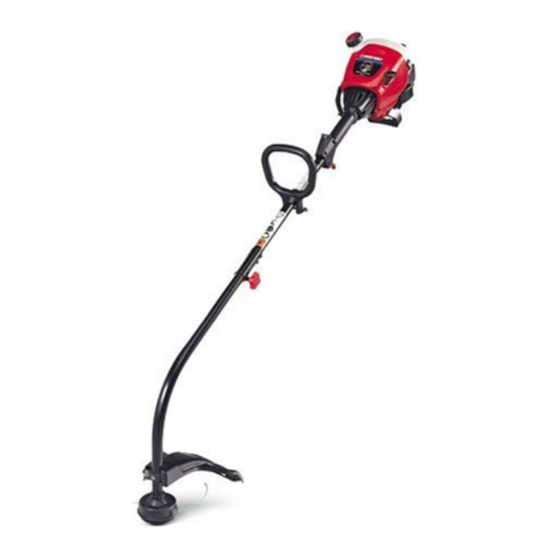
Page 6: Trimmer Overview
APPMCATmONS Blue EZ-Start Lever As a trimmer: • Cutting grass and Hight weeds, • Decorative trimming around trees, fences, etc, Other optional accessories may be used with the TB20CS, Refer to Operadng the EZ-Link .System for Starter Rope Gri f a Hist of add-ons, AirFHter/Muffler Muffler... - Page 7 INSTALL AND ADJUST THE D-HANDLE mNSTALL THE CUTTING ATTACHMENT SHIELD Use the following instructions if the cutting attachment shield on your unit is not installed. The squared bolt hole in the handle is to the right. WARNING: Never Insert the shoulder bolt into the squared hole in the operate trimmer without handle and push through.
-
Page 8: Oil And Fuel Mixing Instructions
OraLAND FUEL MmXH_G H_STRUCTmONS ThorougHy mix the proper ratio of 2-cycb engine oil with unleaded gasoline in a separate fuel can. Use a 40:1 ON and/or improperly mixed fuel are the main reasons fuel/oil ratio. Do not mix them directly in the engine fuel for the unit not running properly. - Page 9 Stop/Off WARBLING: Operateth,s un,t only,na vvell- ventilated outdoor Start/On ( I ) area, Carbon monoxide exhaust fumes can be lethal in a confined area, WARNING: Avoid acddentd starting. Make sure you are in the starting position when pulling the starter rope (Fig. 8). To avoid serious injury, the operator and unit must be Throttle in a staMe position while starting.
- Page 10 OPERATING THE EZ-UNK TM SYSTEM 2. WhiHe firmHy hoHding the add-on, push it straight into the EZ-Link coupHer (Fig. 10). The EZ-LinW M system enabHes the use of these optionaH Add-Ons. NOTE: AHigning the reHease button with the guide recess wiHH heHpinstaHHation(Fig.
- Page 11 HOLDmNG THE TRmMMER NOTE: Do not rest the Bump Head on the ground whiie the unit is running. WARNmNG: AUways wear eye, Some iine breakage wiii occur from: hearing, foot and • Entangiement with foreign matter body protection to reduce the risk of injury when operating this unit, •...
-
Page 12: Maintenance Schedule
SCHEDULE MAmNTENANCE NOTE: Maintenance, repHacement, or repair of the emission controH devices and system may be Perform these required maintenance procedures at the performed by any non-road engine repair frequency stated in the tame. These procedures shouHd estaMishment, individual or authorized service also be a part of any seasonaHtune-up. -
Page 13: Single/Split Line Installation
ForUsewithSingme ForUsewithSplitLine Insert the end of the line into the open hole in the Line ONLY or Singme Line inner reel and pull the line tight to make the loop as small as possible (Fig. 21). 10. Before winding, split the line back about 6 inches. 11. - Page 14 mNSTALUNG A PREWOUND REEL Cleaning the Air Filter Clean and re-oil the air filter every 10 hours of operation. 1. Hold the outer spool with one hand and unscrew the It is an important item to maintain. Failure to maintain bump knob counterclockwise (Fig.
- Page 15 SPARK ARRESTOR MAINTENANCE Replace the two screws you removed in Step 2 and tighten them securely. NOTE: The exhaust can onHyflow in one direction: AWAY Reinstall the air filter/muffler cover. from the engine. Pay chose attention when disassemMing the muffHer so you can put it back together correctHy.
- Page 16 TRANSPORTING Release the throttb trigger and let the engine idle. If the engine stops, insert a small phillips or flat blade • Allow the engine to cool before transporting. screwdriver into the hole in the air filter/muffler cover (Fig. 30). Turn the idle speed screw in, clockwise, 1/8 of a •...
- Page 17 CAUSE ACTION Empty fueHtank Fill fueH tankwithpropedy mixed fueH Primer buHbwasn't pressed enough Press primer bulb fully and slowly 10 times Engine is flooded Squeeze the trigger and pull the starter rope OHdor impropeHy mixed fueH Drain gas tank and add fresh fuel mixture FouHed spark pHug Replace or clean the spark plug Mugged spark arrestor...
- Page 18 Engine Type ............................Air-Cooled, 2-Cycle Stroke ..............................1.25in.(31.75 mm) Displacement ............................. 1.9cu in.(31cc) ClutchType................................. Centrifugal IdleSpeed RPM ............................2,800- 3,600 rpm Operating R PM ..............................7,200+ rpm Ignition Electronic Type ....................Ignition Switch .............................. Rocker Switch Spark Plug Gap ............................0.020 in.
- Page 19 • As the small off-road engine owner, you are responsible for the performance of the required maintenance listed in your operator's manual, Troy-Bilt recommends that you retain all receipts covering maintenance on your small off-road engine, but Troy-Bilt cannot deny warranty solely for the lack of receipts or for your failure to ensure the performance of all scheduled maintenance,...
- Page 20 (90) days from the date of original retail related expenses, or for rental expenses purchase for any Troy-Bilt product that is used for rental or temporarily replace a warranted product. (Some states commercial purposes,...