Garmin G1000 Manual
Integrated flight deck pilot’s training guide
Hide thumbs
Also See for G1000:
- Manual (724 pages) ,
- Pilot's manual (708 pages) ,
- System maintenance manual (340 pages)
Table of Contents
Advertisement
Advertisement
Table of Contents

Related Manuals for Garmin G1000


Summary of Contents for Garmin G1000
- Page 1 Integrated Flight Deck Pilot’s Training Guide...
- Page 2 Except as expressly provided herein, no part of this manual may be reproduced, copied, transmitted, disseminated, downloaded or stored in any storage medium, for any purpose without the express written permission of Garmin. Garmin hereby grants permission to download a single copy of this manual and of any revision to this manual onto a hard drive or other electronic storage medium to be viewed for personal use, provided that such electronic or printed copy of this manual or revision must contain the complete text of this copyright notice and provided further that any unauthorized commercial distribution of this manual or any revision hereto is strictly prohibited.
-
Page 3: Table Of Contents
Flight and Ground Instruction ............................1 Level of Knowledge Attained ............................1 Ground Lesson 1..........................3 INTRODUCTION AND GARMIN INTEGRATED FLIGHT DECK SYSTEM OVERVIEW ..........3 Exercise 1.1:.................................. 3 Terminology and Review of Pertinent Federal Aviation Regulations................3 Exercise 1.2: Component Review ..........................6 Ground Lesson 2..........................9... - Page 4 GFC 700 AUTOMATIC FLIGHT CONTROL SYSTEM (AFCS)................45 Exercise 13.1: Flight Director and Autopilot Operation ....................45 Appendix............................47 CONSIDERATIONS ON USING THE GARMIN INTEGRATED FLIGHT DECK TO ENHANCE THE AERONAUTICAL DECISION MAKING (ADM) PROCESS AND SINGLE-PILOT RESOURCE MANAGEMENT (SRM)......47 GIFD Pilot’s Training Guide...
-
Page 5: Introduction
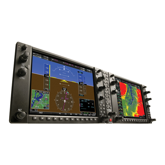
INTRODUCTION GARMIN Integrated Flight Deck (GIFD) The GIFD is a completely integrated avionics system, designed to fit a broad range of aircraft models. It is an all-glass fight deck that presents flight instrumentation, location, navigation, communication, and identification data on large-format, high-resolution displays. The digital data presentation on the GIFD puts all flight-critical information literally at the pilot’s fingertips. - Page 6 BLANK PAGE GIFD Pilot’s Training Guide 190-00368-05 Rev. B...
-
Page 7: Ground Lesson 1
INTRODUCTION AND GIFD SYSTEM OVERVIEW Objectives Upon completion of this lesson, the pilot should be able to do the following: • Describe the basic components of the Garmin Integrated Flight Deck • Describe the communication between GIFD components Resources • GIFD Pilot’s Guide •... - Page 8 • APV Approach with vertical guidance is an International Civil Aviation Organization (ICAO) term referring to specific ICAO criteria adopted in May 2000. This approach classification allows stabilized descent using vertical guidance without the accuracy required for traditional precision approach procedures. The US has developed criteria for lateral/vertical navigation (LNAV/VNAV) and LPV approach procedures that meet this approach classification.
- Page 9 5. When filling a flight plan, what suffix is used for a current Global Positioning System (GPS) database with WAAS? “/G” is the suffix used for GPS flight plans. 6. What are the position accuracy improvements with the WAAS? TSO-C129a systems: •...
-
Page 10: Exercise 1.2: Component Review
An Automatic Flight Control System provides pitch/roll steering guidance and sends commands to an autopilot to operate the flight control surfaces. 2. Describe the function of the following components of the Garmin Integrated Flight Deck: • GRS 77 The Attitude and Heading Reference System (AHRS) provides aircraft attitude and heading information to the Primary Flight Display (PFD) and the primary Integrated Avionics Unit (IAU;... - Page 11 3. What is the primary interface used between the GIFD components? Digital, uni-directional Ethernet buses using a proprietary Garmin protocol are the primary communication links between Line Replaceable Units (LRUs).
- Page 12 BLANK PAGE GIFD Pilot’s Training Guide 190-00368-05 Rev. B...
-
Page 13: Ground Lesson 2
Ground Lesson 2 TRANSITION TO THE PRIMARY FLIGHT DISPLAY (PFD) Objectives Upon completion of this lesson, the pilot should be able to read, understand, and interpret the six primary flight instruments displayed on the PFD that indicate airspeed, attitude, altitude, vertical speed, turn rate/coordination, and heading. -
Page 14: Exercise 2.2: Instrumentation Depiction
Exercise 2.2: Instrumentation Depiction Assume that the aircraft is flying with the following indications and fill in the appropriate fields on the sketch with this data. Note that some data is not displayed for certain GIFD installations. • Airspeed = 140 KIAS •... -
Page 15: Ground Lesson 3
Ground Lesson 3 POWER-UP, SELF-TEST, CHECKLIST Objectives Upon completion of this lesson, the pilot should be able to correctly identify proper alignment of the AHRS/ADC, complete a system self-test, and verify the database data. Resources • GIFD Pilot’s Guide • GIFD PC-based Simulator Exercise 3.1: System Initialization 1. - Page 16 9. A pilot is planning a fight to KAPA (Centennial Airport, Denver, CO) from KCOU (Columbia, MO). When arriving at the aircraft, the pilot notices that the Jeppesen database is out of date by 3 cycles (84 days). • Can the pilot make the flight under Instrument Flight Rules (IFR)? Yes, but one cannot file “/G”...
-
Page 17: Ground Lesson 4
MFD/PFD Control Unit (GCU). 3. Which Garmin LRU failure will cause the GIFD to lose Mode C/S capability? If an Air Data Computer (GDC 74) fails, the GTX 33 Transponder will lose the pressure altitude source, leaving it to operate in Mode A only. -
Page 18: Exercise 4.2: Practice (Optional)
Exercise 4.2: Practice (Optional) Using the GIFD PC-based Simulator, review the start-up process and verify the Jeppesen database effective dates. Also, practice entering various transponder codes and changing the operating mode using the PFD softkeys. GIFD Pilot’s Training Guide 190-00368-05 Rev. B... -
Page 19: Ground Lesson 5
Ground Lesson 5 COM RADIO AND AUDIO PANEL OPERATION Objectives Upon completion of this lesson, the pilot should be comfortable manually and automatically tuning and selecting communication frequencies, while properly configuring the selections on the GMA 1347 Audio Panel. Resources •... -
Page 20: Exercise 5.2: Practice (Optional)
Exercise 5.2: Practice (Optional) Using the GIFD PC-based Simulator, power up the system. 1. Verify the Jeppesen database effective dates and note those dates in the space provided below. 2. Enter the transponder code “3470” and set the transponder to ‘ALT’ mode. 3. -
Page 21: Exercise 5.3: Audio Panel Operation
Exercise 5.3: Audio Panel Operation 1. Which key should be pressed on the Audio Panel (GMA 1347) to monitor a COM radio frequency without transmitting? Press the COM Key for the selected radio (COM1 or COM2) to monitor the desired communication radio. - Page 22 BLANK PAGE GIFD Pilot’s Training Guide 190-00368-05 Rev. B...
-
Page 23: Ground Lesson 6
Ground Lesson 6 NAVIGATION Objectives Upon completion of this lesson, the pilot should be able to navigate using ground-based NAVAIDs and GPS while manually tuning VOR/LOC/ILS frequencies and creating GPS direct-tos and flight plans. Resources • GIFD Pilot’s Guide • GIFD PC-based Simulator Exercise 6.1: Land-based Navigational Aids 1. - Page 24 7. With the NAV radio receiving the tuned VOR station, the corresponding Bearing Information Window displays the distance to bearing. What source provides the distance information? The GPS-derived great circle distance is displayed (note that this is not a DME distance).
-
Page 25: Exercise 6.2: Practice (Optional)
Exercise 6.2: Practice (Optional) Using the GIFD PC-based Simulator, power up the system and configure the GIFD as needed for the following IFR clearance out of KAPA (Centennial Airport, Denver, CO): “N12345 is cleared to the Goodland, KS, airport, via the Thurman VOR, Byers VOR, then direct. -
Page 26: Exercise 6.3: Gps Navigation
Exercise 6.3: GPS Navigation 1. Can a direct-to/flight plan be created using GPS on both the PFD and the MFD or must one or the other be used (if so, which one)? Either display can be used for creating a GPS direct-to or flight plan; the data automatically cross-fills to the other display. -
Page 27: Exercise 6.4: Practice (Optional)
Exercise 6.4: Practice (Optional) Using the GIFD PC based Simulator, power up the system. 1. Verify the Jeppesen database effective dates and note those dates in the space provided below. 2. Enter the transponder code “1252” and set the transponder to ‘ALT’ mode. 3. -
Page 28: Exercise 6.5: Instrument Approaches
Exercise 6.5: Instrument Approaches 1. When first selecting an approach, what is the default option that appears when the PROC Key is pressed? “Select Approach” is the first option displayed when the PROC Key is pressed. 2. What is the difference in how the HSI presents data between selecting Vectors-to-Final or an Initial Approach Fix during an instrument approach? When Vectors-to-Final is selected, the HSI sets the inbound approach course automatically and it can be intercepted in the same way it would when getting vectors to a... - Page 29 9. What key must be pressed to add a departure procedure (DP or SID) and/or arrival procedure (AP or STAR) to a flight plan? Pressing the PROC Key gives access to a list of options that includes adding a departure or arrival procedure.
-
Page 30: Exercise 6.6: Practice (Optional)
Exercise 6.6: Practice (Optional) Using the GIFD PC-based Simulator, power up the system. 1. Verify the Jeppesen database effective dates and note those dates in the space provided below. 2. Enter the transponder code “5455” and set the transponder to ‘ALT’ mode. 3. -
Page 31: Exercise 6.7: Vertical Navigation (Vnav)
Exercise 6.7: Vertical Navigation (VNAV) 1. Where does one go to program a VNAV flight plan on the GIFD? In the flight plan, assign VNAV target altitudes to programmed waypoints for enroute and descent phases of flight. Altitudes may also be loaded from the database. The calculates Tent (TOD) and Bottom Of Decent (BOD) based on ground speed. -
Page 32: Exercise 6.8: Charts
Exercise 6.8: Charts 1. How does one view the Safe-Taxi diagram on the MFD as well as on the PFD? The Safe-Taxi diagram can be viewed by enabling it in the Navigation Map Setup: On the MFD, press and hold down the CLR Key. This returns the MFD to the default MAP –... -
Page 33: Ground Lesson 7
Ground Lesson 7 MULTI FUNCTION DISPLAY (MFD) OPERATION Objectives Upon completion of this lesson, the pilot should be able to locate, use, and configure data on the MFD during flight operations. Resources • GIFD Pilot’s Guide • GIFD PC-based Simulator Exercise 7.1: MFD Configuration and Controls 1. - Page 34 8. Which page should be accessed in order to change the navigation data field options at the top of the MFD display? The AUX - System Setup Page provides options for changing the navigation information displayed in the MFD Navigation Data Box. 9.
-
Page 35: Ground Lesson 8
Ground Lesson 8 PRIMARY FLIGHT DISPLAY (PFD) OPERATION Objectives Upon completion of this lesson, the pilot should be able to configure and interpret data presented on the PFD during all phases of flight operations. Resources • GIFD Pilot’s Guide • GIFD PC-based Simulator Exercise 8.1: PFD Configuration and Controls 1. - Page 36 9. Where is the control for the Altimeter barometric pressure setting located? The BARO Knob is located on the right-hand side of the PFD (in some installations, exists as the large outer knob of the CRS/BARO Knob). 10. What are the ranges of viewable tape in the Altimeter and Airspeed Indicator? The Altimeter has 600 feet viewable at a time;...
-
Page 37: Ground Lesson 9
Ground Lesson 9 EMERGENCY PROCEDURES Objectives Upon completion of this lesson, the pilot should be able to determine the types of emergencies with associated component failures and take appropriate action during emergencies or failures. Resources • GIFD Pilot’s Guide • GIFD PC-based Simulator Exercise 9.1: Emergencies and Failure Modes 1. - Page 38 6. During a cross country flight, an AHRS failure occurs (failure indicated by a red “X” over the Attitude Indicator). Note: the aircraft is equipped with a GFC 700 AFCS. • Aside from the backup Attitude Indicator, what items can be used to ensure safe flight? •...
-
Page 39: Ground Lesson 10
Terrain Awareness. TAWS also provides aural alerts and additional pop-up visual alerts. 3. List the types of alerts that Garmin TAWS-B offers. 1. Forward Looking Terrain Avoidance (FLTA) 2. Forward Looking Obstacle Avoidance (FLOA) 3. - Page 40 6. During which phase of flight is PDA active? PDA functions only during descent to land. 7. The NCR is only active during the departure phase of the flight. What condition(s) must exist to activate this alert? 1. Height above the terrain must be less than 700 feet. 2.
-
Page 41: Ground Lesson 11
Ground Lesson 11 TRAFFIC OPERATION Objectives Upon completion of this lesson, the pilot should be able to accurately interpret traffic data while both incorporating this information into the aeronautical decision making (ADM) process and understanding the limitations of these systems. Resources •... - Page 42 7. When a Traffic Advisory is issued, is one allowed to deviate from the ATC assigned instructions? No, the traffic display is intended to assist the pilot in visual acquisition of these aircraft in VMC. TIS is not intended to be used as a collision avoidance system and does not relive the pilot responsibility to “see and avoid”...
-
Page 43: Ground Lesson 12
Ground Lesson 12 WEATHER OPERATION Objectives Upon completion of this lesson, the pilot should be able to understand and interpret weather information displayed in the cockpit. The pilot will be able to use this supporting information to enhance the decision-making process before and during the flight. Resources •... - Page 44 3. List all XM Weather Products and their corresponding update rates. NEXRAD 5 min Cloud Tops 15 min Cell Movement 12 min County Warnings 5 min METARs 12 min AIRMETs 12 min TAFs 12 min SIGMETs 12 min Lightning 5 min Echo Tops 7.5 min TFRs...
- Page 45 10. A pilot is on a VFR flight from KXYZ to KABC. Currently, the altitude is 9,500 feet, 50 miles from KABC. Weather is predicted to be MVFR at the destination airport. Using the MFD, describe the steps that must be taken to receive a METAR and/or TAF at the destination airport.
-
Page 46: Exercise 12.2: Lightning Detection
Exercise 12.2: Lightning Detection 1. When flying an aircraft with a WX-500 Stormscope installed, where can the lightning data be displayed? Stormscope information can be shown on the PFD Inset Map and on the MFD Navigation Map and Stormscope pages. 2. -
Page 47: Exercise 12.3: Weather Radar
Exercise 12.3: Weather Radar 1. Does the GWX 68 Airborne Weather Radar allow you to operate while on the ground? Yes, however, a caution will appear alerting the pilot to follow all safety precautions. WARNING: Begin transmitting only when it is safe to do so. If it is desired to transmit while the aircraft is on the ground, no personnel or objects should be within 11 feet of the antenna. - Page 48 BLANK PAGE GIFD Pilot’s Training Guide 190-00368-05 Rev. B...
-
Page 49: Ground Lesson 13
GFC 700 AUTOMATIC FLIGHT CONTROL SYSTEM (AFCS) Objectives Upon completion of this lesson, the pilot should be able to understand the operation of the Garmin Automatic Flight Control System (AFCS) and use the autopilot throughout various phases of flight. Resources •... - Page 50 7. When the go-around control is pressed, what flight director and autopilot functions can be expected? Pressing the go-around control engages the flight director in the wings level, nose up attitude and the autopilot disengages automatically. 8. List several ways the autopilot can be disengaged. When there is a system failure, automatic disengagement occurs.
-
Page 51: Appendix
DECK TO ENHANCE THE AERONAUTICAL DECISION MAKING (ADM) PROCESS AND SINGLE-PILOT RESOURCE MANAGEMENT (SRM) The Garmin Integrated Flight Deck has brought a number of improvements in cockpit technology to General Aviation (GA) aircraft. These improvements range from longer life and greater reliability of the primary instruments to a simplified pilot interface. -
Page 52: Flight Planning
emergency. Nonetheless, it is imperative that the pilot double-check all autopilot inputs in order to avoid mode confusion and monitor them to ensure that the intended operation is taking place. If equipped with a GFC 700 AFCS, it is also important for pilots to understand the capabilities and limitations of the system. - Page 53 WEATHER AWARENESS In this discussion so far, the focus has been on SRM. Now, attention will be turned to leveraging the various data inputs from the on-board weather sensors, datalinks, traffic awareness, and terrain awareness functions. Proper understanding of both the operation of these various tools and their integration with the pilot’s aeronautical decision making (ADM) process can bring significant safety gains to the GA feet.
- Page 54 TRAFFIC AWARENSS Traffic Collision and Avoidance Systems (TCAS) represent another technological advance that has been made in the area of traffic avoidance. Originally developed for large commercial aircraft, TCAS technology is now starting to trickle down features and capabilities to the GA feet. For example, the GTX 33 Mode-S Transponder can be used as an optional component in GIFD- equipped aircraft and brings Traffic Information Service (TIS) data directly to the cockpit.
- Page 55 FINAL THOUGHTS In conclusion, as GA aircraft and pilots transition to 21st-century technology, the Garmin Integrated Flight Deck provides a number of safety-enhancing benefits. Although automation in the cockpit should be embraced, both its positive and negative impacts on the safety of flight should be recognized and understood.
- Page 56 BLANK PAGE GIFD Pilot’s Training Guide 190-00368-05 Rev. B...
- Page 57 Garmin International, Inc. 1200 East 151st Street Olathe, KS 66062, U.S.A. p:913.397.8200 f:913.397.8282 Garmin AT, Inc. 2345 Turner Road SE Salem, OR 97302, U.S.A. p:503.391.3411 f:503.364.2138 Garmin (Europe) Ltd. Liberty House, Bulls Copse Road Houndsdown Business Park Southampton, SO40 9RB, U.K.