Troy-Bilt 2620 Operator's Manual
Two stage snow thrower
Hide thumbs
Also See for 2620:
- Operator's manual (56 pages) ,
- Operator's manual (28 pages) ,
- Operator's manual (31 pages)
Table of Contents
Advertisement
Available languages
Available languages
Safe Operation Practices • Set-Up • Operation • Maintenance • Service • Troubleshooting • Warranty
O
'
M
peratOr
s
anual
Two-Stage Snow Thrower — Storm 2620
WARNING
READ AND FOLLOW ALL SAFETY RULES AND INSTRUCTIONS IN THIS MANUAL
BEFORE ATTEMPTING TO OPERATE THIS MACHINE.
FAILURE TO COMPLY WITH THESE INSTRUCTIONS MAY RESULT IN PERSONAL INJURY.
TROY-BILT LLC, P.O. BOX 361131 CLEVELAND, OHIO 44136-0019
Printed In USA
Form No. 769-04038
(May 23, 2008)
Advertisement
Table of Contents

Related Manuals for Troy-Bilt 2620


Summary of Contents for Troy-Bilt 2620
- Page 1 READ AND FOLLOW ALL SAFETY RULES AND INSTRUCTIONS IN THIS MANUAL BEFORE ATTEMPTING TO OPERATE THIS MACHINE. FAILURE TO COMPLY WITH THESE INSTRUCTIONS MAY RESULT IN PERSONAL INJURY. TROY-BILT LLC, P.O. BOX 361131 CLEVELAND, OHIO 44136-0019 Printed In USA Form No. 769-04038...
-
Page 2: Table Of Contents
Call a Customer Support Representative at (800) 828-5500 or (330) 558-7220 ◊ Write us at Troy-Bilt LLC • P.O. Box 361131 • Cleveland, OH • 44136-0019 If you have any problems or questions concerning the unit, phone a authorized Troy-Bilt service dealer or contact us directly. -
Page 3: Important Safe Operation Practices
Important Safe Operation Practices WARNING! This symbol points out important safety instructions which, if not followed, could endanger the personal safety and/or property of yourself and others. Read and follow all instructions in this manual before attempting to operate this machine. Failure to comply with these instructions may result in personal injury. - Page 4 Safe Handling of Gasoline To avoid personal injury or property damage use extreme care in handling gasoline. Gasoline is extremely flammable and the vapors are explosive. Serious personal injury can occur when gasoline is spilled on yourself or your clothes which can ignite. Wash your skin and change clothes immediately.
- Page 5 Maintenance & Storage Never tamper with safety devices. Check their proper operation regularly. Refer to the maintenance and adjustment sections of this manual. Before cleaning, repairing, or inspecting machine disengage all control levers and stop the engine. Wait until the auger/impeller come to a complete stop. Disconnect the spark plug wire and ground against the engine to prevent unintended starting.
-
Page 6: Safety Symbols
Safety Symbols This page depicts and describes safety symbols that may appear on this product. Read, understand, and follow all instructions on the machine before attempting to assemble and operate. Symbol WARNING! Your Responsibility—Restrict the use of this power machine to persons who read, understand and follow the warnings and instructions in this manual and on the machine. -
Page 7: Assembly & Set-Up
Assembly & Set-Up Contents of Carton • One Snow Thrower • One Snow Thrower Operator’s Manual Assembly Handle Place the shift lever in the Forward-6 position Observe the lower rear area of the snow thrower to be sure both cables are aligned with roller guides before pivoting the handle upward. - Page 8 Finish securing chute control assembly to chute support bracket with wing nut and hex screw removed earlier. See Fig. 3-4. Figure 3-4 Check that all cables are properly routed through the cable guide on top of the engine. See Fig. 3-5. Figure 3-5 3—...
-
Page 9: Adding Fuel
Fuel Recommendations Use automotive gasoline (unleaded or low leaded to minimize combustion chamber deposits) with a minimum of 87 octane. Gasoline with up to 10% ethanol or 15% MTBE (Methyl Tertiary Butyl Ether) can be used. Never use an oil/gasoline mixture or dirty gasoline. - Page 10 Adjustments Skid Shoes The snow thrower skid shoes are adjusted upward at the factory for shipping purposes. Adjust them downward, if desired, prior to operating the snow thrower. CAUTION: It is not recommended that you operate this snow thrower on gravel as it can easily pick up and throw loose gravel, causing personal injury or damage to the snow thrower and surrounding property.
-
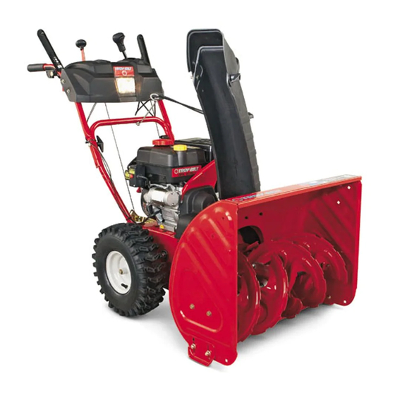
Page 11: Controls & Features
Controls and Features Drive Control Gas Cap Chute Assembly Oil Fill Clean Out Tool Augers Snow thrower controls and features are described below and illustrated in Fig. 4-1. Shift Lever The shift lever is located in the right side of the handle panel and is used to determine ground speed and direction of travel. - Page 12 Throttle Control The throttle control is located on the rear of the engine. It regulates the speed of the engine and will shut off the engine when moved into the STOP position. Primer Pressing the primer forces fuel directly into the engine’s carburetor to aid in cold- weather starting.
- Page 13 Chute Directional Control PUSH PUSH BUTTON BUTTON CHUTE CHUTE ROTATE ROTATE RIGHT LEFT The chute directional control is located on the left side of the dash panel. • To change the direction in which snow is thrown, squeeze the button on the joy-stick and pivot the joy-stick to the right or to the left.
-
Page 14: Starting Engine
Operation Starting the Engine WARNING! Always keep hands and feet clear of moving parts. Do not use a pressurized starting fluid. Vapors are flammable. NOTE: Allow the engine to warm up for a few minutes after starting. The engine will not develop full power until it reaches operating temperatures. -
Page 15: Stopping The Engine
Recoil Starter CAUTION! Do not pull the starter handle while the engine running. WARNING: To avoid unsupervised engine operation, never leave the engine unattended while running. Turn the engine off after use and remove ignition key Insert ignition key fully into slot, Figure 5-5. Make sure it snaps into place. -
Page 16: Maintenance & Adjustment
Maintenance & Adjustments Maintenance Engine Refer to the Engine Maintenance section. Shave Plate and Skid Shoes The shave plate and skid shoes on the bottom of the snow thrower are subject to wear. They should be checked periodically and replaced when necessary. To remove skid shoes: Remove the four carriage bolts and hex flange nuts which secure them to the snow thrower. -
Page 17: Adjustments
Auger Shaft At least once a season, remove the shear pins from the auger shaft. Spray lubricant inside the shaft and around the spacers and the flange bearings found at either end of the shaft. See Fig. 6-3. Figure 6-3 Adjustments Shift Cable If the full range of speeds (forward and reverse) cannot be... - Page 18 Drive Control When the drive control is released and in the disengaged “up” position, the cable should have very little slack. It should NOT be tight. NOTE: If excessive slack is present in the drive cable or if the snow thrower’s drive is disengaging intermittently during operation, the cable may be in need of adjustment.
-
Page 19: Changing Engine Oil
Engine Maintenance WARNING! To prevent accidental start-up, shut off the engine and remove the ignition key before performing any type of engine maintenance. Maintenance Schedule Tasks First 5 Hrs. Each Use or Every 5 Hrs. Check engine oil Change engine oil Check spark plug Service spark plug Clean exhaust area... -
Page 20: Spark Plug
Spark Plug WARNING! DO NOT check for spark with spark plug removed. DO NOT crank engine with spark plug removed. WARNING! If the engine has been running, the muffler will be very hot. Be careful not to touch the muffler. To ensure proper engine operation, the spark plug must be properly gapped and free of deposits. -
Page 21: Belt Replacement
Service Belt Replacement Auger Belt To remove and replace your snow thrower’s auger belt, proceed as follows: Allow the engine to run until it is out of fuel. Remove the plastic belt cover on the front of the engine by removing the two self-tapping screws. - Page 22 Remove the belt from around the auger pulley, and slip the belt between the support bracket and the auger pulley. See Fig. 8-5. Figure 8-5 Reassemble auger belt by following instructions in reverse order. NOTE: Do not forget to reinstall the shoulder screw and reconnect the spring to the frame after installing a replacement auger belt.
-
Page 23: Friction Wheel Removal
Slip the drive belt off the pulley and between friction wheel and friction wheel disc. See Fig. 8-7. Figure 8-7 Remove and replace belt in the reverse order. NOTE: Engaging the drive control will ease reassembly of the belt. Friction Wheel Removal If the snow thrower fails to drive with the drive control engaged, and performing the drive control cable adjustment fails to correct the problem, the friction wheel may need to be replaced. - Page 24 Carefully remove the hex nut which secures the hex shaft to the snow thrower frame and lightly tap the shaft’s end to dislodge the ball bearing from the right side of the frame. See Fig. 8-9. NOTE: Be careful not to damage the threads on the shaft. Figure 8-9 Carefully position the hex shaft downward and to the left before carefully sliding the friction wheel assembly off the...
-
Page 25: Troubleshooting
Troubleshooting Problem Engine fails to start Choke not in ON position. Spark plug wire disconnected. Fuel tank empty or stale fuel. Engine not primed. Faulty spark plug. Safety key not in ignition on engine. Engine runs erratic Engine running on CHOKE. Stale fuel. -
Page 26: Replacement Parts
Replacement Parts Component Phone (800) 828-5500 to order replacement parts or a complete Parts Manual (have your full model number and serial number ready). Parts Manual downloads are also available free of charge at www.troybilt.com. Part Number and Description 929-0071 Extention Cord, 110V 954-04050 Auger Drive Belt... - Page 27 Notes...
- Page 28 Troy-Bilt LLC (Troy-Bilt) and The United States Environment Protection Agency (U. S. EPA) The U. S. EPA and Troy-Bilt are pleased to explain the emissions control system warranty on your model year 2005 and later small off-road engine. New small off-road engines must be designed, built and equipped to meet the stringent anti-smog standards. Troy-Bilt must warranty the emission control system on your engine for the period of time listed below, provided there has been no abuse, neglect or improper maintenance of your small off-road engine.
- Page 29 (c) Troy-Bilt will include a copy of the following emission warranty parts list with each new engine, using those portions of the list applicable to the engine.
- Page 30 MANUFACTURER’S LIMITED WARRANTY FOR The limited warranty set forth below is given by Troy-Bilt LLC with respect to new merchandise purchased and used in the United States and/or its territories and possessions, and by MTD Products Limited with respect to new merchandise purchased and used in Canada and/or its territories and possessions (either entity respectively, “Troy-Bilt”).
- Page 31 Medidas importantes de seguridad • Configuración • Funcionamiento • Mantenimiento • Servicio • Solución de problemas • Garantía anual del peradOr Máquina quitanieve de dos etapas — Storm 2620 ADVERTENCIA LEA Y SIGA TODAS LAS INSTRUCCIONES DE ESTE MANUAL ANTES DE PONER EN FUNCIONAMIENTO ESTA MÁQUINA.
- Page 32 Llame a un representante de Asistencia al Cliente al (800) 828-5500 ó (330) 558-7220 ◊ Escríbanos a Troy-Bilt LLC • P.O. Box 361131 • Cleveland, OH • 44136-0019 Troy-Bilt LLC se reserva el derecho de modificar las especificaciones de los productos, los diseños y el equipo estándar sin previo aviso y sin generar responsabilidad por...
- Page 33 Medidas importantes de seguridad ADVERTENCIA! ¡ La presencia de este símbolo indica que se trata de instrucciones importantes de seguridad que se deben respetar para evitar poner en peligro su seguridad personal y/o material y la de otras personas. Lea y siga todas las instrucciones de este manual antes de poner en funcionamiento esta máquina.
- Page 34 Manejo seguro de la gasolina Para evitar lesiones personales o daños materiales tenga mucho cuidado cuando trabaje con gasolina. La gasolina es sumamente inflamable y sus vapores pueden causar explosiones. Si se derrama gasolina encima o sobre la ropa se puede lesionar gravemente ya que se puede incendiar.
- Page 35 Mantenimiento y Almacenamiento Nunca altere los dispositivos de seguridad. Controle periódicamente que funcionen correctamente. Remítase a las secciones de mantenimiento y ajuste de este manual. Antes de realizar la limpieza, reparar o revisar la máquina, desengrane todas las palancas de control y detenga el motor.
- Page 36 Símbolos de Seguridad Esta página describe los símbolos y figuras de seguridad internacionales que pueden aparecer en este producto. Lea el manual del operador para obtener la información terminada sobre seguridad, reunirse, operación y mantenimiento y reparación. Símbolo ¡ADVERTENCIA! Su para Restringir responsabilidad el uso de esta máquina de poder a personas que leyeron, entienda y siga las advertencias e instrucciones en este manual y en la máquina.
- Page 37 Montaje y Configuración Contenido de la caja • Una máquina quitanieve • Un Manual del Operador de la Máquina Quitanieve Montaje Manija Coloque la palanca de cambios en la posición de avance (F) 6. Observe el área inferior trasera de la máquina quitanieve para asegurarse de que ambos cables estén alineados con las guías rotatorias antes de girar la manija hacia arriba.
- Page 38 Termine de asegurar el montaje de control del canal a la ménsula de soporte del canal con la tuerca de mariposa y el tornillo hexagonal retirados anteriormente. Vea la Fig. 3-4. Figura 3-4 Controle que todos los cables estén adecuadamente dirigidos a través de la guía de cables de la parte superior del motor.
- Page 39 Recomendaciones sobre el combustible Utilice gasolina para automóviles (sin plomo o con bajo contenido de plomo para minimizar los depósitos en la cámara de combustión) con un octanaje mínimo de 87. Se puede usar gasolina con hasta un 10% de etanol o un 15% de MTBE (éter metílico terciario-butílico).
- Page 40 Ajustes Zapatas antideslizantes Las zapatas antideslizantes de la máquina quitanieve se ajustan para arriba en fábrica para el envío. Si lo desea, puede ajustarlas hacia abajo antes de hacer funcionar la máquina quitanieve. PRECAUCIÓN: Se recomienda no operar esta máquina quitanieve sobre grava ya que puede recoger y lanzar grava suelta fácilmente, causando lesiones personales o daños a la máquina y los objetos que la rodean.
- Page 41 Controles y Características Control de Transmisión Tapón de combustible Montaje del canal Llenado de aceite Herramienta de limpieza del canal Barrenas Los controles y características de la máquina quitanieve se describen a continuación y se ilustran en la Fig. 4-1. NOTA: Para obtener información detallada sobre todos los controles del motor, consulte el manual de operación Tecumseh para motores que se entrega por separado.
- Page 42 Control del regulador El control del regulador está ubicado en la parte trasera del motor. Regula la velocidad del motor, y lo apaga cuando se lo coloca en la posición STOP (detención). Cebador Al presionar el cebador se envía combustible directamente al carburador del motor para ayudar al encendido cuando el clima es frío.
- Page 43 Control direccional del canal El control direccional del canal está ubicado del lado izquierdo del panel de instrumentos. • Para cambiar la dirección en que se quita la nieve, apriete el botón de la palanca de mando y gire la palanca a derecha o izquierda.
- Page 44 Funcionamiento Encendido del motor ¡ADVERTENCIA! Siempre mantenga las manos y los pies alejados de las partes móviles. No utilice fluidos comprimidos para arrancar. Los vapores son inflamables. NOTA: Deje que el motor se caliente durante unos minutos tras el arranque. El motor no desarrollará toda su potencia hasta que alcance temperaturas operativas.
- Page 45 Una vez que el motor esté en funcionamiento, desconecte del arrancador eléctrico el cable de alimentación. Para desconectarlo, desenchufe siempre el extremo que está enchufado al tomacorriente de pared antes de desenchufar el extremo opuesto que está conectado al motor. Arrancador de retroceso ¡PRECAUCIÓN! No tire de la manija del arrancador...
- Page 46 Mantenimiento y Ajustes Mantenimiento Motor Consulte el sección de Motor Mantenimiento para ver el mantenimiento del motor. Placa de raspado y zapatas antideslizantes La placa de raspado y las zapatas antideslizantes ubicadas en la base de la máquina quitanieve están sujetas a desgaste. Periódicamente debería controlar los pernos y reemplazarlos cuando sea necesario.
- Page 47 Eje de la barrena Al menos una vez por temporada, quite los pasadores de cuchilla del eje de la barrena. Rocíe lubricante en el interior del eje y alrededor de los separadores y los cojinetes bridados que se encuentran en ambos extremos del eje. Vea la Fig. 6-3. Figura 6-3 Ajustes Cable de cambios...
- Page 48 Control de la transmisión Cuando se suelta el control de la transmisión y está en posición desenganchada arriba, el cable debe tener muy poco juego. NO debe estar tenso. NOTA: Si el cable de transmisión tiene demasiado juego o si la transmisión de la máquina quitanieve se desengrana intermitentemente durante la operación, es posible que deba ajustar el cable.
-
Page 49: Mantenimiento Del Motor
Mantenimiento del motor ¡ADVERTENCIA! Para evitar el arranque accidental, apague el motor y retire la llave de encendido antes de realizar cualquier tipo de mantenimiento del motor. Calendario de mantenimiento Tareas Primeras Cada uso o cada 5 horas 5 horas Controlar aceite del motor Cambiar aceite del... - Page 50 Bujía de encendido ¡ADVERTENCIA! NO pruebe la chispa si no está la bujía de encendido. NO dé arranque al motor si no está la bujía de encendido. ¡ADVERTENCIA! Si el motor ha estado funcionando, el silenciador estará muy caliente. Tenga cuidado de no tocar el silenciador. Para asegurarse de que el motor funcione bien, la bujía debe tener una separación correcta y no tener sedimentos.
- Page 51 Servicio Cambio de correa Correa de la barrena Para retirar y reemplazar la correa de la barrena de su máquina quitanieve, proceda como se indica a continuación: Para evitar derrames, coloque un trozo de envoltura de plástico debajo del tapón de combustible y ajuste bien. Saque la cubierta plástica de la correa ubicada en el frente del motor.
- Page 52 Retire la correa de alrededor de la polea de la barrena y deslice la misma entre la ménsula de soporte y la polea de la barrena. Vea la Fig. 8-5. Figura 8-5 Para realizar el reensamblado de la correa de la barrena siga las instrucciones en orden inverso.
- Page 53 Deslice la correa de la transmisión fuera de la polea y de entre la rueda de fricción y el disco de la rueda de fricción. Figura 8-7 Vea la Fig. 8-7. Retire y reemplace la correa en el orden inverso. NOTA: Engranando el control de la transmisión se facilita el montaje de la correa.
- Page 54 Retire con cuidado la tuerca hexagonal y la arandela que sujetan el eje hexagonal al marco de la máquina quitanieve, y golpee suavemente el extremo del eje para desplazar el cojinete de bolas del lado derecho del marco. Vea la Fig. 8-9. NOTA: Tenga cuidado de no dañar las roscas del eje.
- Page 55 Solución de Problemas Problema El motor no arranca El con ON (encendido). Se ha desconectado el cable de la bujía. El depósito de combustible está vacío o el combustible se ha echado a perder. El motor no está cebado. La bujía no funciona correctamente. La llave de seguridad no se ha insertado.
- Page 56 Piezas de Reemplazo Componente Llame por teléfono al (800) 828-5500 para solicitar piezas de reemplazo o un Manual de Piezas de Repuesto completo (tenga el número de modelo y número de serie de su máquina a mano). En www.troybilt.com también podrá descargar el Manual de Piezas de Repuesto sin cargo alguno.
- Page 57 Notas...
- Page 58 (Derechos y obligaciones del propietario según la garantía contra defectos) La U. S. EPA y Troy-Bilt se complacen en explicar la garantía del sistema de control de emisiones de su motor para equipo todo terreno, modelo, año 2005 y versiones posteriores. Los nuevos motores pequeños para equipo todo terreno se deben diseñar, fabricar y equipar para cumplir con las rigurosas normas contra la polución.
- Page 59 (c) Troy-Bilt incluirá una copia de la siguiente lista de piezas bajo garantía contra emisiones con cada nuevo motor, utilizando las partes de la lista aplicables al motor.
- Page 60 Las disposiciones de esta garantía cubren el recurso de reparación única y exclusiva que surge de la venta. Troy-Bilt no se hará responsable de ninguna pérdida o daño incidental o resultante, incluyendo sin limitación, los gastos incurridos para los servicios de mantenimiento del césped, o los gastos de arrendamiento para...