ProForm 790 E User Manual
Pfel079090
Hide thumbs
Also See for 790 E:
- Manuel de l'utilisateur (16 pages) ,
- Bedienungsanleitung (16 pages) ,
- Manual (16 pages)
Table of Contents
Advertisement
www.proform.com
Model No. PFEL07909.0
Serial No.
Write the serial number in the
space above for reference.
\
Serial Number Decal
(on underside of frame)
QUESTIONS?
If you have questions, or if parts are
damaged or missing, DO NOT
CONTACT THE STORE; please
contact Customer
Care.
IMPORTANT: Please register this
product (see the limited warranty
on the back cover of this manual)
before contacting Customer Care.
CALL TOLL-FREE:
1-888-533-1333
Mon.-Fri.
6 a.m.-6 p.m. MT
Sat. 8 a.m.-4
p.m. MT
ON THE WEB:
www.proformservice.com
A UAL
®
Advertisement
Table of Contents

Related Manuals for ProForm 790 E


Summary of Contents for ProForm 790 E
- Page 1 ® www.proform.com Model No. PFEL07909.0 A UAL Serial No. Write the serial number in the space above for reference. Serial Number Decal (on underside of frame) QUESTIONS? If you have questions, or if parts are damaged or missing, DO NOT CONTACT THE STORE;...
-
Page 2: Table Of Contents
Apply the decal in the location shown. Note: The decal(s) may not be shown at actual size. PROFORM is a registered trademark of ICON IP, Inc. -
Page 3: Important Precautions
iMPORTANT PRECAUTIONS... -
Page 4: Before You Begin
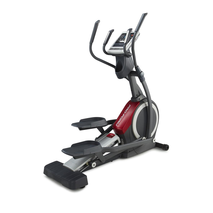
BEFORE YOU BEGIN Thank you for selecting the revolutionary PROFORM ® cover of this manual. To help us assist you, note the 790 E elliptical exerciser. The 790 E elliptical exerciser product model number and serial number before con- provides an impressive selection of features designed tacting us. -
Page 5: Assembly
ASSEMBLY To hire an authorized service technician to assemble the elliptical exerciser, call 1-800-445-2480. Assembly requires two persons. Place all parts of the elliptical exerciser in a cleared area and remove the packing materials. Do not dispose of the packing materials until assembly is completed. In addition to the included tool(s),... - Page 6 Attach the Front Stabilizer (6) to the Front Frame (1) with two M8 x 80mm Patch Screws (84). Orient the Rear Stabilizer (62) and the Rear Frame (2) as shown. Tip: If the Ramp Cover (see step 15) is attached to the Ramp (3), remove the Ramp Cover.
- Page 7 Insert the Rear Frame (2) into the Front Frame (1); make sure that the Ramp (3) is on the Lift Roller (12). Attach the Rear Frame (2) with five M8 x 19mm Patch Screws (82) and five M8 Split Washers (83).
- Page 8 Apply a generous amount of grease to the Pivot Axle (35) and to two Wave Washers (95). Insert the Pivot Axle (35) through the Upright (4) and then center it. Slide a Wave Washer (95) onto each end of the Pivot Axle (35).
- Page 9 See the inset drawing. Slide an Inner Cover (68) onto the Right Upper Body Leg (60). Opening Next, slide the Right Upper Body Leg (60) onto the right end of the Pivot Axle (35); make sure that the Right Upper Body Leg is in front of the right Crank Arm (20).
-
Page 10: Orient The Rear Upright Cover (80) As Shown
Have a second person hold the Console (7) near the Upright (4). Avoid pinching the wires Connect the wires on the Console (7) to the Ground Wire (120), to the Pulse Wires (63, 69), and to the Upper Wire Harness (110). Insert the excess wires up into the Console (7) or down into the Upright (4). - Page 11 12. Apply a small amount of grease to the right Crank Arm (20). Orient a Roller Arm (45) so that the Roller (51) is in the position shown. Slide the Roller Arm (45) onto the right Crank Arm (20) while setting the Roller (51) on the Grease Ramp (3).
- Page 12 14. See the upper drawing. Apply a small amount of grease to the axle on the Right Upper Body Leg (60) and to the axle on the Right Pedal Arm (58). Grease Orient the Right Pedal Arm (58) as shown. Slide the Right Pedal Arm onto the Right Upper Body Leg (60) and into the right Roller Arm (45) at the same time.
-
Page 13: How To Use The Elliptical Exerciser
HOW TO USE THE ELLiPTiCAL EXERCISER HOW TO PLUG IN THE POWER CORD HOW TO MOVE THE ELLIPTICAL EXERCISER This product must be grounded, if it should mal- Due to the size and weight of the elliptical function or break down, grounding provides a path of exerciser, moving it requires two persons. - Page 14 HOW TO EXERCISE ON THE ELLiPTiCAL EXERCISER Upper Body Arm_ To mount the elliptical exerciser, hold the upper body arms and step onto the pedal that is in the lower posi- tion. Then, step onto the other pedal. Push the pedals until they begin to move with a continuous motion.
- Page 15 CONSOLE DIAGRAM DISPLAY l_--"_ R ES 1 STAN C E ,,_ --_" MP31N_ FEATURES OF THE CONSOLE The console features the iFit interactive workout sys- tem, which enables the console to accept iFit cards The advanced console offers an array of features containing workouts designed to help you achieve designed to make your workouts more effective and specific fitness goals.
- Page 16 HOW TO TURN ON THE POWER Change the resistance of the pedals and the incline of the ramp as desired. iMPORTANT: if the elliptical exerciser has been exposed to cold temperatures, allow it to warm to room temperature before turning on the power, if change the resis- you do not do this, you may damage the console...
- Page 17 When your pulse is display--This dis- detected, a flashing heart symbol will play can show the t_'..__ -w-_U appear in the dis- elapsed time, the _'_J distance that you _ ,, play, and then your heart rate will have pedaled, your pedaling speed, and the approximate number of appear.
- Page 18 s °uexerc L" / HOW TO USE A PRESET WORKOUT keep your pedaling speed near the tar- Begin pedaling or press any button on the SPEED console to turn on the console. get speed for the current segment, At See HOW TO TURN ON THE POWER on page the beginning of each segment, the target speed for the segment will flash in the display.
- Page 19 HOW TO USE AN IFIT WORKOUT HOW TO USE THE SOUND SYSTEM iFit cards are available separately. To purchase iFit To play music or audio books through the console cards, go to www.iFit.com or see the front cover of this sound system while you exercise, plug the included manual, iFit cards are also available at select stores.
-
Page 20: Maintenance And Troubleshooting
MAINTENANCE AND TROUBLESHOOTING HOW TO ADJUST THE DRIVE BELT Inspect and tighten all parts of the elliptical exerciser regularly. Replace any worn parts immediately. If the pedals slip while you are pedaling, even while To clean the elliptical exerciser, use a damp cloth and the resistance is adjusted to the highest level, the a small amount of mild soap. - Page 21 HOW TO ADJUST THE REED SWITCH Locate the Reed Switch (38). Rotate the Pulley (19) until a Magnet (43) is aligned with the Reed Switch. Next, loosen but do not remove the indicated M4 x If the console does not display correct feedback, the reed switch should be adjusted.
-
Page 22: Exercise Guidelines
EXERCISE GUiDELiNES Burning Fat--To burn fat effectively, you must exer- cise at a low intensity level for a sustained period of time, During the first few minutes of exercise, your body uses carbohydrate calories for energy. Only after the first few minutes of exercise does your body begin to use stored fat calories for energy, If your goal is to burn fat, adjust the intensity of your exercise until your heart rate is near the lowest number in your training... -
Page 23: Part List
PART LiST--Model No. PFEL07909.0 Rl109A Note: To locate the parts listed below, see the EXPLODED DRAWING near the end of this manual. Key No. Qty. Description Key No. Qty. Description Front Frame Roller Rear Frame Pedal Arm Cap Axle Cover Ramp Clevis Pin Upright... - Page 24 Key No. Qty. Description Key No. Qty. Description Idler Screw Drive Belt M8 Locknut Audio Cable M3.5 x 12mm Flat Head Screw #6 x 9.5mm Screw M4 x 16mm Screw Upper Bushing Lower Wire Harness Mount M4 x 16mm Bright Screw Motor Bracket Screw Roller Arm Bushing Small Snap Ring...
-
Page 25: Exploded Drawing
EXPLODED DRAWING Am Model No. PFEL07909.0 RllogA ¢.o L("__... - Page 26 EXPLODED DRAWING B mlVlodel No. PFEL07909.0 Rl109A...
- Page 27 EXPLODED DRAWING CmlVlodel No. PFEL07909.0 Rl109A L£)
-
Page 28: Ordering Replacement Parts
ORDERING REPLACEMENT PARTS To order replacement parts, please see the front cover of this manual. To help us assist you, be prepared to provide the following information when contacting us: - the model number and serial number of the product (see the front cover of this manual) - the name of the product (see the front cover of this manual) - the key number and description of the replacement part(s) (see the PART LIST and the EXPLODED DRAWING near the end of this manual)