Table of Contents
Advertisement
Quick Links
Extron Electronics, USA
Extron Electronics, Europe
1230 South Lewis Street
Beeldschermweg 6C
Anaheim, CA 92805
3821 AH Amersfoort
USA
The Netherlands
714.491.1500
+31.33.453.4040
www.extron.com
Fax 714.491.1517
Fax +31.33.453.4050
© 2002 Extron Electronics. All rights reserved.
Extron Electronics, Asia
Extron Electronics, Japan
135 Joo Seng Road, #04-01
Daisan DMJ Building 6F
PM Industrial Building
3-9-1 Kudan Minami
Singapore 368363
Chiyoda-ku, Tokyo 102-0074 Japan
+65.6383.4400
+81.3.3511.7655
Fax +65.6383.4664
Fax +81.3.3511.7656
User's Manual
RGB 202 R xi xi xi xi xi , RGB 202 R xi xi xi xi xi VTG
Universal Interfaces with Stereo Audio and ADSP
™
68-500-01
Printed in the USA
Advertisement
Table of Contents

Related Manuals for Extron electronics RGB 202 Rxi VTG


Summary of Contents for Extron electronics RGB 202 Rxi VTG
- Page 1 Extron Electronics, USA Extron Electronics, Europe Extron Electronics, Asia 1230 South Lewis Street Beeldschermweg 6C 135 Joo Seng Road, #04-01 Anaheim, CA 92805 3821 AH Amersfoort PM Industrial Building The Netherlands Singapore 368363 714.491.1500 +31.33.453.4040 +65.6383.4400 www.extron.com Fax 714.491.1517 Fax +31.33.453.4050 Fax +65.6383.4664 ©...
-
Page 2: Part Numbers
Precautions Safety Instructions • English Warning This symbol is intended to alert the user of important Power sources • This equipment should be operated only from the power source indicated on the product. This equipment is intended to be used with a main operating and maintenance (servicing) instructions power system with a grounded (neutral) conductor. -
Page 3: Table Of Contents
LCD Display ... 2-14 LCD screen backlight ... 2-14 Scan rate indication ... 2-14 Centering ... 2-14 Operating the VTG (RGB 202 Rxi xi xi xi xi VTG only) Troubleshooting ... 2-16 Chapter 3 • Remote Control ... 3-1 RS-232 Programmer’s Guide ... -
Page 4: Chapter 1 • Introduction
RGB 202 Rx x x x x i i i i i , RGB 202 Rx x x x x i i i i i VTG 68-500-01 Rev. C Printed in the USA 03 02 Chapter One Introduction About this Manual About the RGB 202 Rxi and RGB 202 Rxi VTG Features... -
Page 5: About This Manual
RGB 202 Rxi and RGB 202 Rxi VTG universal interfaces and on how to operate and configure them. About the RGB 202 Rxi xi xi xi xi and RGB 202 Rxi xi xi xi xi VTG The RGB 202 Rxi is an analog computer-video interface with 300 MHz (-3dB) video bandwidth and Advanced Digital Sync Processing™. -
Page 6: Additional Rgb 202 Rxi Vtg Feature
Introduction, cont’d Additional RGB 202 Rxi xi xi xi xi VTG feature Video test generator — The RGB 202 Rxi VTG includes a 4-resolution, 4-pattern video test generator to simplify system setup and testing. RGB 202 Rx x x x x i i i i i , RGB 202 Rx x x x x i i i i i VTG • Introduction... -
Page 7: Installation And Operation Overview
This is an overview of the installation process. You will find detailed installation and operation instructions in this chapter. To install and set up the RGB 202 Rxi and RGB 202 Rxi VTG interfaces, follow these basic steps: Turn all of the equipment (computers, remote controls, interface, projector/monitor, local monitor, and speakers or other audio device) off. -
Page 8: Through-Desk Mounting
Installation and Operation, cont’d Through-desk mounting If rubber feet were installed on the interface, remove them. Insert the machine screws (provided in the mounting kit) through the slots in the optional through-desk mounting brackets (part #70-077-02), and loosely attach the brackets to the interface. -
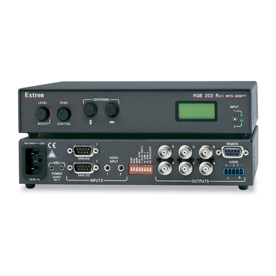
Page 9: Front Panel
16-position rotary switch. Four different video test patterns are available for each of the four resolutions offered by the RGB 202 Rxi VTG’s built-in mini video test generator. See “Operating the VTG” in this chapter for more information. -
Page 10: Rear Panel
Installation and Operation, cont’d 202 (interface)/VTG selection switch (RGB 202 Rxi VTG only) — Use this switch to select the output signal’s source 202 = The image from the interface (from input 1 or input 2) will be displayed. VTG = A test pattern generated by the VTG (video test generator) will be displayed. -
Page 11: Cabling
RGB 202 Rx x x x x i i i i i , RGB 202 Rx x x x x i i i i i VTG • Installation and Operation 2-10 8 — No Backlight — This switch controls illumination of the LCD backlight. - Page 12 RGBS For sync on green (SOG, RGsB), connect the cables as shown here, and also select the SOG option on the rear panel DIP switch. RGsB Connect the local monitors to the monitor breakout cables if they were used in step 1 to connect the computers to the interface.
-
Page 13: Lcd Display
Installation and Operation, cont’d LCD Display The RGB 202 Rxi and RGB 202 Rxi VTG’s front panel LCD display serves two main functions: to display the scanning rates of the input signal, and to indicate the horizontal and vertical centering limits. During VTG operation, the RGB 202 Rxi VTG’s LCD displays the VTG format, resolution and refresh rates. -
Page 14: Chapter One
To test the system setup and output, substitute a video test generator for one of the computer inputs. Use the VTG that is built into the RGB 202 Rxi VTG, or use a stand-alone VTG with the RGB 202 Rxi. To use a stand-alone VTG, unplug the input/output devices’... -
Page 15: Chapter 3 • Remote Control
Installation and Operation, cont’d RGB 202 Rx x x x x i i i i i , RGB 202 Rx x x x x i i i i i VTG Chapter Three Remote Control RS-232 Programmer’s Guide Contact Closure Control RGB 202 Rx x x x x i i i i i , RGB 202 Rx x x x x i i i i i VTG •... -
Page 16: Rs-232 Programmer's Guide
The input number has been changed or, for the RGB 202 Rxi VTG, the VTG has been turned on or off. When the interface receives a valid SIS command, it executes the command and sends a response to the host device. -
Page 17: Control Software For Windows
Simple Instruction Set commands listed on page 3-4. The control software is compatible with Windows 3.1x, Windows 95/ 98, and Windows NT. The RGB 202 Rxi and RGB 202 Rxi VTG use version 2.0 or higher of Extron’s RGB 302/304/202 Control Program, which is included with these interfaces. -
Page 18: Specifications
Remote Control, cont’d Contact Closure Remote Control For remote control of input selection only, connect a contact closure remote control device to the rear panel 9-pin D female Remote connector. See the pin assignment table on page 3-2. RGB 202 Rx x x x x i i i i i , RGB 202 Rx x x x x i i i i i VTG • Remote Control RGB 202 Rx x x x x i i i i i , RGB 202 Rx x x x x i i i i i VTG Appendix Specifications, Accessories and... - Page 19 Return loss ... -30dB @ 5 MHz Maximum DC offset ... 4V Video signal characteristics — RGB 202 Rxi xi xi xi xi VTG only Dot clock ... VGA 25.18 MHz, Mac 30.04 MHz, SVGA 65.04 MHz, SGI 107.4 MHz ..
-
Page 20: Included Parts
RGB 202 Rx x x x x i i i i i , RGB 202 Rx x x x x i i i i i VTG • Accessories and Part Numbers These items are included in each order for a RGB 202 Rxi or a... - Page 21 Accessories and Part Numbers, cont’d Laptop breakout cables LBC VGA HR 6’ LBC Mac HR 6’ LBC Sun HR 6’ (61 kHz) LBC Sun HR 6’ (71 kHz) LBC Sun HR 6’ (81 kHz) LBC VGA HR 6’ A LBC Mac HR 6’ A LBC Sun HR 6’...