Advertisement
Advertisement

Related Manuals for Mitsubishi WS-73907


Summary of Contents for Mitsubishi WS-73907
- Page 1 _ MITSUBISHI THE BIG SCREENCOMPANY...
- Page 2 • Consult the dealer or an experienced radio/TV technician for help. Changes or modifications not expressly approved by Mitsubishi could void the user's authority to operate this equipment. WARNING: TO REDUCE THE RISK OF FIRE OR ELECTRIC SHOCK, DO NOT EXPOSE...
-
Page 3: Table Of Contents
Appendix A: Bypassing the V-Chip Lock ......................Appendix B: High Definition Inputs Connection Compatibility ............... Appendix C: Remote Control Programing Codes ..................... Appendix D: Cleaning and Service ........................Appendix E: Troubleshooting ..........................Index ................................. 65-66 Mitsubishi Projection TV Limited Warranty ....................... - Page 4 Read, Retain and Follow All Instructions Read all safety and operating instructions before operating the TV. Retain the safety and operating instructions for future reference. Follow all operating and use instructions. Heed Warnings Adhere to all warnings on the appliance and in the operating instructions. Cleaning Unplug the TV from the wall outlet before cleaning.
- Page 5 IMPORTANT SAFEGUARDS Continued Power Lines An outside antenna system should not be located in the vicinity of overhead power lines or other electric light or power circuits, or where it can fall into such power lines or circuits. When installing an outside antenna system, extreme care should be taken to keep from touching such power lines or circuits as contact with them might be fatal.
- Page 8 Part I: Thank You e at Mitsubishi Would Like to Thank You To the Mitsubishi Consumer: Thank you for choosing Mitsubishi as your premier home entertainment partner. Whether this is your first Mitsubishi consumer electronics product or an addition to your growing...
- Page 9 V-Chip Technology Mitsubishi understands that you may want to shield certain viewers from specific program content. Your Mitsubishi bigscreen will allow you to restrict Programming by general con- tents, specific contents, or even by time. See pages 36-38. (3) IR Emitter Cables...
- Page 12 Part I1: Installation Control Panel {MONO) ..Oo S.V]OEO V_D_O L-AUOFO ENTR • _N_UT_ u- ADj_/S r _ Figure I. Front Control Panel. IRIS Intelligent Room Illumination (light) Sensor. Turn this feature on or off using the VIDEO button on your remote control. When the IRIS is on, your TV will automatically adjust picture contrast and brightness for the best picture based on your room lighting.
- Page 13 Part I1: Installation Back Panel ®®®® ® ®®®®® ® ®®®®® ER EMITTER HOME THEATER ®®®4 STB (Set-Top-Box) This input can be used for the connection of any device with an S-Video output. Inputs These inputs can be used for the connection of a VCR, Super VHS (S-VHS) VCR, laser disc player, or other A/V device to the TV.
- Page 14 PIP/POP inset. 1080i when those signals are being received. How Connections Affect the System 4 Home Theater IR Control The Mitsubishi System 4 Home Theater IR to change inputs. You will automatically Control is a special feature that makes it...
- Page 15 A/V receivers input marked TV. The products listed at the top of this column connect to the below listed Model inputs on the back of the appropriate A/V receiver. Brand SAT/DBS/DTV TV / Cable Mitsubishi M-VR1000 / M-VR800 VCR2 VCR1 Mitsubsihi M-VR900/ M-VR700 CABLE/DBS...
- Page 16 Part I1: Installation an Antenna, Wall Outlet Cable, or Cable Box /Ch_n_=els 2-_3} (Cha_=n_*ls _4.69) Separate UHF and VHF Antennas (Figure 1) Connect the UHF and VHF antenna leads to the UHF/VHF combiner. Push the combiner onto ANT-A on the TV back panel.
- Page 17 Part I1: Installation Connecting a VCR TV_ckp_l Antennas or Wall Outlet Cable (Figure 1) Connect the incoming cable to ANT-A the TV back panel. Connect two coaxial cables as follows: One from LOOP-OUT on the TV back panel to ANTENNA IN on the VCR back panel. One from VCR back panel ANTENNA OUT to ANT-B on the TV back panel.
- Page 18 Part I1: Installation an Audio Receiver Stereo Audio System 3"V back partel (Figure 1) Connect the audio cables from AUDIO MONITOR OUTPUT on the TV back panel to TV IN or AUX IN terminals on the back of the audio system. The red cable connects to the R (right) channel,...
- Page 19 Part I1: Installation WARNING: Connecting a DVD Player TV t_:k _a_el DVD Player with Component Video (Figure 1) Connect the Component Video cables from Y/Cr/Cb or Y/Pr/Pb VIDEO OUT on the back of the DVD player to COM- PONENT-1 or COMPONENT-2 on the DVD bac_ pane( TV back panel, matching the correct...
- Page 20 Part I1: Installation (Figure 1) The TV back panel has 5 RCA-type connec- tors, for the DTV connection. The back panel of your DTV receiver may use RCA- type connectors or BNC-type connectors. your DTV receiver comes with BNC type connections, you will need to purchase BNC BNC to...
- Page 21 Part I1: Installation Connecting a DTV Receiver DTV Receiver with RGB Video Connections (Figure 1) Connect the outside antenna, cable, or satellite to ANT, or SATELLITE IN on the DTV receiver (see your DTV receiver's owner's guide for instructions, and cable compatibility).
- Page 22 Part I1: Installation Connecting a Computer with a VGA Monitor Output TVbaC_pan_ Connecting a Computer (Figure 1) Connect VGA Monitor Out from the com- puter to VGA on the TV back panel i ¸¸ i_ ill using a VGA compatible monitor cable.
- Page 23 Part I1: Installation Warning: Do not leave stationary, toolbar, or partial images on-screen for extended periods of time. Mix the types of pictures shown. Uneven picture tube aging is NOT covered by your warranty. We recommend that screen saver acti- The VGA capability of this television vation time be set to less than five...
- Page 26 Part II1: Setup Programming the Remote Control: To Control Other AN Products Program the Remote to Control Other Brands of Audio and Video Products: POWER (Figures 1-5) Move the slide switch at the top of the remote to the product you want to Satellite brand Codeto enter: If your...
- Page 27 CD player ill youhavea MitsubishiA/V Pioneer 205,207 listing. receiver, the audio position may be used in conjunction with Sony select Mitsubishi CD players. Your audio position must be Yamaha 201,202 programmed to either 010 or 011. Plug the CD player power To reset to default code, enter 000 cord into a switched outlet on the back of your A/V receiver.
- Page 28 Part II1: Setup Programming the Remote Control: To Activate the System 4 Home Theater IR Control Activation of the System 4 Home Theater IR Control To Activate the Audio Portion: For select brands of digital A/V receivers', you can set up the remote control to auto- (Figure 1) matically select the correct audio input when Press and hold the HOME THEATER button.
- Page 29 Part II1: Setup Programming the Remote Control: To Activate the System 4 Home Theater IR Control Testing System 4 for Proper Setup If the TV did not change inputs... Repeat To Activate the Video Portion, page Move the slide switch to the position you 28, and retest.
- Page 30 Part II1: Setup 3D Graphical ! llJ l/lll®Menu System Your TV has Mitsubishi's exclusive 3D Graphical I_1_1111 ® on-screen operating system, which provides on-screen informa- tion for menu choices and changes (Figure1). A picture (icon) will be highlighted when selected with the ADJUST arrows.
- Page 31 Part II1: Setup Menu Screens (Overview) Setup Menu (Figure 1) You can put channels in memory, turn on or off input connections of the TV, and select the menu system to display in English or Espa5ol (Spanish). Figure 1. Setup menu Captions Menu (Figure 2) Display captions or text, and choose black or...
- Page 32 Part II1: Setup Menu Screens (Overview) p Lock Menu (Figure 1) Block or allow programing based upon rating signals sent by the broadcast station, or by time. Advanced Menu Figure 1. V-Chip Lock menu (Figure 2) Set your TV to turn on automatically, con- verge (align) the three main colors, display a blue screen when viewing an input with...
- Page 33 Part II1: Setup Setup Menu: Memorize Channels, Assign Input, and Lane Memorize Channels (Figure 1) This selection memorizes the channels your TV can receive and skips the unused or weak channels. You can stop memorization at any time by pressing CANCEL. Channels memorized prior to pressing CANCEL will...
- Page 34 Part II1: Setup Menu: Closed Captions Captions Menu (Figure 1) Broadcasters can send either Standard or Text closed captioning. Standard closed captioning follows the dialogue of the char- acters on-screen and displays in a small sec- tion of the screen. Text closed captioning often contains information such as weather...
- Page 35 Part II1: Setup Channel Menu: Antenna, Channel, Memory, Name, and SQV (Super Quick View Using The Menu Screen (Figure 1) SQV (Super Quick View allows you to put together a list of your favorite channels from Ant-A and Ant-B. You can store up to 6 channels in each of the 9 different memory banks.
- Page 36 Part II1: Setup p Menu: V-Chip Lock p Lock (Figure 1) The V-Chip Lock allows you to Block or Allow programs based upon rating signals sent by the broadcasting station. The TV comes from the factory with the V-Chip lock in the Off setting.
- Page 37 Part II1: Setup V-Chip Menu: V-ChipLock Ant-A 002 KCBS V-Chip Signal Information 480i Standard (Figure 1) When provided by the broadcaster, V-Chip signal information can be displayed by press- _ing the INFO button on the remote control. Rating guidelines are provided by broadcast stations.
- Page 38 Part II1: Setup p Menu: V-Chip Lock Hours/Time V-Chip Lock Hours/Time (Figure 1) V-CHIP HOURS/LOCK BY TIME will allow you to activate the V-Chip or lock the entire TV during specific hours. V-Chip Start Time and V-Chip Stop Time (Figure 1) Figure 1.
- Page 39 Part II1: Setup Advanced Menu: Timer Timer (Figure 1) The timer will automatically turn the TV on (if it is off) at the time you schedule and select. Figure 1. Timer selection in the Advanced menu Figure 2. Timer menu Timer Menu (Figure 2) Select the days that the TV will turn on auto-...
- Page 40 Part II1: Setup Menu: Convergence Convergence (Figure 1) Your Mitsubishi TV has three picture tubes which are aligned to properly converge the projected light beams on the screen. Each picture tube projects a single color of red, blue or green.
- Page 41 Brighter scenes will not be affected. Video Display (Figure 2) Your Mitsubishi TV will double the lines of a standard 480i (interlaced) picture to pro- duce a smoother, more film like image. have two choices for your selection; 480p or 960i.
- Page 42 Part II1: Setup Menu: AV Memory Reset, and Audio/Video Settings AUDIO/VIDEO SETTINGS menu (Figure 1) Each of the 11 inputs has its own A/V memory. You can adjust each input's A/V memory in two ways. You can use the menu, or the remote control. Memory Reset A/V Memory Reset will return the currently...
- Page 43 Part II1: Setup Audio/Video Menu: TV Speakers, and Audio Output TV Speakers (Figure 1) This selection will turn on or off the TV's internal speakers. You may select Off when sending the sound through a sepa- rate stereo system or surround sound A/V receiver.
- Page 44 Part II1: Setup Menu: Clock Setting (Manual) Clock Setting (Manual) (Figure 1) For the manual clock setting, select the cur- rent time, including AM or PM. Press • or • to slowly adjust the time. Press and hold • or • to quickly adjust the time.
- Page 45 Part II1: Setup Clock Menu: Clock Setting (Auto) Clock Setting (Auto) (Figure 1) Setting the Clock Setting to Auto will automatically set the day and time using Extended Data Service (XDS) time data. This data is automatically retrieved from a PBS channel or other channel carrying this service.
- Page 46 Part II1: Setup Setting Descriptions: Audio Audio Settings • Mono: Reduces background noise, and Bass enhances or reduces low fre- should be used when receiving a weak quency sound. stereo audio signal. All audio will be played [] Treble enhances or reduces high fre- mono with this setting.
- Page 47 Part II1: Setup A/V Setting Descriptions: Video Video Settings IRIS is the Intelligent Room Illumi- Video Noise reduces minor noise (grain- nation (light) Sensor. When IRIS iness) in the broadcast or input signal. on, your TV will automatically adjust pic- Image Type maximizes the original ture contrast and brightness...
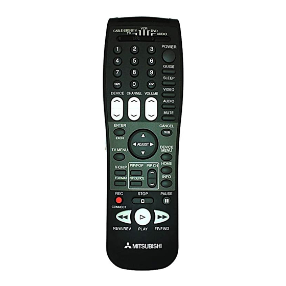
- Page 50 Part IV: Operation Remote Control Functions: Overview Overv,ew (Following page, figure 1) tion. Slide Switch: Select A/V product to be CANCEL: Clear SQV and some menu controlled by the remote control. entries. Numbers: Individually select channels MENU: Display 3D Graphical i_J_101]r ' or input information into TV.
- Page 51 ([] of figure 1) to the appropriate position. remote control has been preset to operate the TV and other Mitsubishi products. program the remote control to operate other Figure 2. Installing the batteries. products, see Use of the Remote Control...
- Page 52 Remote Control Functions: System 4 Home Theater IR Control to change inputs. You will automatically The Mitsubishi System 4 Home Theater IR hear the high quality digital surround sound Control is a special feature that makes it...
- Page 53 Part IV: Operation Remote Control Functions: System 4 Home Theater IR Control Requirements for Operation A/V devices connected as described on page 15. Cable Box connected as on page 16 or Cable Box with an S-Video output conneced on page 19, Connecting an S-Video Device.
- Page 54 Part IV: Operation Remote Control Functions: Special Functions _'_ When_ your remote control has been Pro- grammed to operate another manufacturer's product, the function performed on each layer can vary. The most common functions are: • POWER • PLAY • PAUSE •...
- Page 55 Part IV: Operation Remote Control Functions: Operation of PIP and POP Changing PIP/POP Inputs Press PIP INPUT to cycle through available MAIN PICTURE Side-by-Side inputs. To see which inputs can and cannot be used together, see How Connections Affect the PIP and POP - Table 1, page 14. Changing PIP/POP Channels...
- Page 56 Part IV: Operation Remote Control Functions: Display Formats This is a wide screen "IV (also known as Standard: This is the full screen format. a 18:9 TV). This shape reflects the new HDTV signals will automatically use this types of images available from HDTV and format.
- Page 57 Part IV: Operation Non-Anamorphic Picture (4:3) Anamorphic Widescreen Picture (16:9)
- Page 58 Part IV: Operation Warning: Do not leave stationary or letterbox images on-screen extended periods of time. Mix the types of pictures shown. Uneven picture tube aging is NOT covered by your warranty. The normal use of a TV should include Still or stationary images may be received from broadcasters,...
-
Page 59: Appendix A: Bypassing The V-Chip Lock
Appendix A: Bypassing the V-Chip Lock I Appendix A: B passin the V-Chip Lock Bypassing the V-Chip Lock After you set the lock, you need your passcode to view a V-Chip locked pro- gram, view the locked TV, cancel the lock, or enter the V-Chip lock menus. -
Page 61: Appendix B: High Definition Inputs Connection Compatibility
DTV receivers that offer RGB. (when using separate H and V sync) your DTV receiver offers both DTV compo- nent video signals and DTV RGB signals, Mitsubishi suggests you use the DTV com- ponent video signals. Please check the... -
Page 62: Appendix C: Remote Control Programing Codes
Appendix C: Remote Control Pro rammin Codes Cable Box VCRs A/V Receivers ABC .... Mitsubishi ..010, 011,012, 013, 014, Mitsubishi ..001,002, 060, 067, 068, 061 ......Archer ..132, 125 Admiral ..Admiral ..Cablaview ..105, 132 Aiwa .... -
Page 63: Appendix D: Cleaning And Service
Normally, light dusting with a dry, non- If you are unable to correct a problem with scratching duster will keep your TV clean. your TV, consult your Mitsubishi dealer or Use care when cleaning your TV with any a Mitsubishi... -
Page 64: Appendix E: Troubleshooting
Appendix E: Troubleshooting • The TV remote control does not work. , Check that the batteries are installed correctly. Check that the selected switch is set to "TV". , Be no further than 20 feet from the TV when using the remote control •... -
Page 65: Index
Index espafiol, maintenance, 2, 67 adding and deleting channels EXCH button on remote, Advanced Features menu 39 memorize channels, memory (channel), adaptors (BNC to RCA), 20 adjusting (convergence), 40-41 alignment (convergence), 40-41 antennas (connecting), formats (display), 56-57 assistance, front control panel, naming channels, audio settings... - Page 66 Video Display, 41 960i, 41 Video Mute, 41 Sleep Timer, 52 Video Settings, sound (adjusting), Spanish, Special Functions, SQV (Super Quick View TM), Mitsubishi Limited Warranty, stand, 4 STATIONARY PICTURE WARNING, 19, 23, 58 surface, 4, 63 surges, time (setting), 44-45...
-
Page 67: Mitsubishi Projection Tv Limited Warranty
Labor, For 30 days after the original purchase at retail, we will repair or replace, at our option, the lenticular screen if it proves defective. For all other parts, we will provide the labor for a warranty repair by an authorized MITSUBISHI service center without charge for one year from the original date or purchase at retail c.