Table of Contents
Advertisement
®
With Universal
Dock for iPod ®
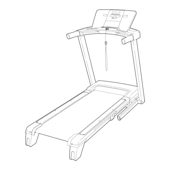
Model No. NTL07007.1
Serial No.
Write the serial number in the space
above for reference.
Serial
Decal
QUESTIONS?
As a manufacturer, we are com-
mitted to providing complete cus-
tomer satisfaction, If you have
questions, or if parts are missing,
PLEASE DO NOT CONTACT
THE STORE; please contact
Customer
Care.
iMPORTANT:
You must note the
product
model number and
serial number (see the drawing
above) before contacting
us:
CALL TOLL-FREE:
1-888-825-2588
Mon.-Fri.
6 a.m.-6
p.m. MST
Sat. 8 a.m.-4
p.m. MST
ON THE WEB:
www.nordictrackservice.com
SE 'S
A UAL
www.nordictrack.com
new products,
prizes,
fitness tips, and much more!
Advertisement
Table of Contents

Related Manuals for NordicTrack A2350


Summary of Contents for NordicTrack A2350
- Page 1 You must note the product model number and serial number (see the drawing above) before contacting CALL TOLL-FREE: 1-888-825-2588 Mon.-Fri. 6 a.m.-6 p.m. MST Sat. 8 a.m.-4 p.m. MST ON THE WEB: www.nordictrackservice.com www.nordictrack.com new products, prizes, fitness tips, and much more!
- Page 2 •Never t[y to adjust or f_xthe belt whle it is movinp, •Always wear athlefJc shoes wNle operating treadmill, NordicTrack is a registered trademark of ICON IP, Inc. iPod _ is a trademark of Apple Computer, Inc., registered in the U.S. and other countries...
- Page 3 12. To purchase a surge suppressor, informed of all warnings and precautions. your local NordicTrack dealer or call the tele- phone number on the front cover of this man- Use the treadmill only as described.
- Page 4 20. Never leave the treadmill unattended while it inspect and properly tighten all parts of the is running. Always remove the key, unplug treadmill regularly. the power cord, and switch the reset/off cir- DANGER: A ways unplug the power cuit breaker to the off position when the treadmill is not in use.
- Page 5 BEFORE YOU BEGIN Thank you for selecting the revolutionary NordicTrack ® ing this manual, please see the front cover of this man- A2350 treadmill with Universal Dock for iPod ®.The ual. To help us assist you, note the product model A2350 treadmill offers a selection of features designed number and serial number before contacting us.
- Page 6 ASSEMBLY Assembly requires two persons. Set the treadmill in a cleared area and remove all packing materials. Do not dispose of the packing materials until assembly is completed. Note: The underside of the treadmill walking belt is coated with high-performance lubricant.
- Page 7 Make sure that the power cord is unplugged. With the help of a second person, carefully tip the treadmill onto its left side. Partially fold the Hole Frame (56) so that the treadmill is more stable; do not fully fold the Frame yet. Remove and discard the two indicated bolts (A) and the shipping bracket (B).
- Page 8 Setthe RightUpright S pacer ( 79)ontheBase (83).Becarefulnotto pinchthe UprightWire (38).Withthehelpofa second person, h olda BoltSpacer ( 80)inside the lower endofthe RightUpright ( 78).Insert a 3/8"x 4" Bolt(6)with a 3/8"StarWasher ( 9)intothe RightUpright andtheBoltSpacer. R epeat t his stepwith a secondBolt Spacer (80), 3/8"...
- Page 9 Attach theTray(90)tothe handrail assembly withtwo#8x 1/2"Screws (1). Handrail Withthehelpofa second person, h oldthe Assembly handrail assembly n earthe RightUpright ( 78) andthe LeftUpright ( 74).Connect theUpright Wire(38)totheconsole assembly w ire.Seethe inset drawing. The connectors should slide together easily and snap into place. If they do not, turn one connector and try again.
- Page 10 10. Insert the wires from the console assembly into the Handrail assembly. Console Attach the console assembly to the handrail as- Assembly sembly with four 1/4" x 3/4" Bolts (5). Be careful not to pinch the wires. Handrail Assembly Wires 11.
- Page 11 If you purchase the optional chest pulse sensor (see page 22), follow the steps below to install the re= ceiver included with the chest pulse sensor. Make sure that the power cord is unplugged. Remove the indicated #8 x 3/4" Screw (12) and the Access Door (87) from the Console Back Small (91).
- Page 12 Outlet Box the right). To purchase a surge suppressor, /rl_ /11 _J J Adapter your local NordicTrack dealer or call the telephone number on the front cover of this manual and order part number 146148, or see your local electronics store.
- Page 13 CONSOLE DIAGRAM L-=.I lmBll _:sE::s E ::s E::£'Z:_£:::sE::s E ::s _ ::s "" :,.-,3 3I 23"5q _lMr FEATURES OFTHECONSOLE Additional iFIT Cards are available separately. To purchase iFIT Cards at any time, call the tele- The treadmill console offers an impressive array of phone number on the front cover of this manual.
- Page 14 HOW TO TURN ON THE POWER HOW TO USE THE MANUAL MODE IMPORTANT: if the treadmill has been exposed to Insert the key into the console. cold temperatures, allow it to warm to room tern= See HOW TO TURN ON THE POWER to the left. perature before turning on the power, if you do not...
- Page 15 Change the incline of the treadmill as desired. The Fitness Age Calculator display-- To change the incline of the treadmill, press the The Fitness Age Incline increase and decrease buttons or one of Calculator display is the numbered 1 Step Incline buttons. Each time used during the fitness one of the buttons is pressed, the incline will grad- test and can show your...
- Page 16 Measure your heart rate if desired. When you are finished exercising, remove the key from the console. Before using the handgrip Step onto the foot rails, press the Stop button, and pulse sensor, adjust the incline of the treadmill to the lowest remove the setting.
- Page 17 HOW TO USE A PRESET WORKOUT segment of the workout. The height of the flashing segment indicates the speed setting for the current insert the key into the console. segment. At the end of each segment, a series of tones will sound and the next segment of the profile See HOW TO TURN ON THE POWER on page will begin to flash.
- Page 18 HOW TO USE THE CUSTOM WORKOUT CENTER During the workout, the Current Segment profile will show your __===__ insert the key into the console. progress. The flashing segment of the profile See HOW TO TURN ON THE POWER on page represents the current segment of the workout.
- Page 19 HOW TO USE THE FITNESS TEST WORKOUT Test button. Note: Pressing the Start Fitness Test button at this time will not start the fitness test workout. The fitness test workout measures your approximate fitness age. Your fitness age is the average age of someone at your fitness level.
- Page 20 The workout is de- HOW TO USE THE SOUND SYSTEM signed to last for nine minutes. When the This product has been designed specifically to work workout ends, the with iPod and has been certified by the developer to meet Apple performance standards.
- Page 21 HOW TO USE AN IFIT CARD Press the Start button to start the workout. Insert the key into the console. A moment after you press the button, the treadmill will automatically adjust to the first speed and in- See HOW TO TURN ON THE POWER on page cline settings of the workout.
- Page 22 THE iNFORMATiON MODE HOW TO ADJUST THE CUSHiONiNG SYSTEM The console features an information mode that allows Remove the key from the console and unplug the you to select miles or kilometers as the unit of mea- power cord. The treadmill features a cushioning sys- surement.
- Page 23 HOW TO FOLD AND MOVE THE TREADMILL HOW TO FOLD THE TREADMILL FOR STORAGE Before folding the treadmill, adjust the incline to the lowest position, if you do not do this, you may damage the treadmill when you fold it. Remove the key and unplug the power cord.
- Page 24 HOW TO LOWER THE TREADMILL FOR USE 1. Hold the upper end of the treadmill with your right hand. Pull the latch knob to the left and hold it. It may be neces- sary to push the frame forward as you pull the knob to the left, Pivot the frame downward and release the latch knob, Latch...
- Page 25 TROUBLESHOOTING Most treadmill problems can be solved by following the steps below. Find the symptom that applies, and follow the steps listed. If further assistance is needed, please see the front cover of this manual. PROBLEM: The power does not turn on SOLUTION: a, Make sure that the power cord is plugged into a surge suppressor, and that the surge suppressor is plugged into a properly grounded outlet (see page 12).
- Page 26 Remove the three #8 x 3/4" Screws (12) and care- fully pivot the Hood (61) off. Locate the Reed Switch (71) and the Magnet (50) on the left side of the Pulley (51). Turn the Pulley until the Magnet is aligned with the Reed Switch. Make sure that the gap between the Magnet and 1/8 in.- the Reed Switch is about 1/8 in.
- Page 27 PROBLEM: The walking belt is off=center or slips when walked on SOLUTION: a. If the walking belt is off-center, first remove the key and UNPLUG THE POWER CORD. If the walking belt has shifted to the left, use the hex key to turn the left rear roller bolt clockwise 1/2 of a turn;...
- Page 28 EXERCISE GUiDELiNES Burning Fat--To burn fat effectively, you must exer- cise at a low intensity level for a sustained period of time. During the first few minutes of exercise, your body uses carbohydrate ca/oriesfor energy. Only after the first few minutes of exercise does your body begin to use stored fatca/or/esfor energy.
- Page 29 SUGGESTED STRETCHES The correct form for several basic stretches is shown at the right. Move slowly as you stretch--never bounce. 1. Toe Touch Stretch Stand with your knees bent slightly and slowly bend forward from your hips. Allow your back and shoulders to relax as you reach down toward your toes as far as possible.
- Page 30 PART LIST--IVlodel No. NTL07007.1 R0108A To locate the parts listed below, see the EXPLODED DRAWING near the end of this manual. Key No. Qty. Description Key No. Qty. Description #8 x 1/2" Screw Front Roller/Pulley #8 x 1" Tek Screw 15 1/2"...
- Page 31 Key No. Qty. Description Key No. Qty. Description Pulse Bar Ground Wire iFIT Card Kit 6" Blue Wire, 2F Latch Endcap Filter Wire User's Manual Lift Motor Spacer #8 x 2" Screw *These parts are not illustrated. Specifications are subject to change without notice. Right Handrail Trim Frame/Roller Ground Wire...
- Page 32 EXPLODED DRAWING AmModel No. NTL07007.1 R010sA...
- Page 33 EXPLODED DRAWING B--Model No. NTL07007.1 R010SA 39 _ _--24...
- Page 34 EXPLODED DRAWING C--Model No. NTL07007.1 R010SA ._77 lllllll 85--...
- Page 35 EXPLODED DRAWING D--Model No. NTL07007.1 R010SA ,_108 &---1...
- Page 36 ORDERING REPLACEMENT PARTS To order replacement parts, please see the front cover of this manual. To help us assist you, be prepared to pro- vide the following information when contacting us: - the model number and serial number of the product (see the front cover of this manual) - the name of the product (see the front cover of this manual) - the key number and description of the replacement part(s) (see the PART LIST and the EXPLODED DRAW- ING near the end of this manual)