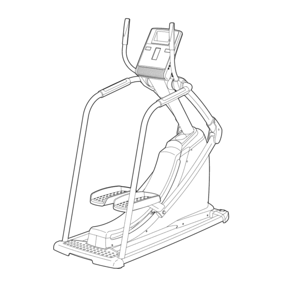
NordicTrack FREESTRIDER 35 S User Manual
Elliptical strider
Hide thumbs
Also See for FREESTRIDER 35 S:
- User manual (28 pages) ,
- Manual (24 pages) ,
- Manuel de l'utilisateur (24 pages)
Table of Contents
Advertisement
Fl-_
iF iFS-rF_
ill]Ell_
S_
S
www.nordictrack.com
Model No. NTSR01909.0
Serial No.
Write the serial number in the space
above for reference.
Serial
Number
Decal
QUESTIONS?
As a manufacturer, we are commit-
ted to providing complete customer
satisfaction. If you have questions,
or if parts are damaged or missing,
DO NOT CONTACT THE STORE;
please contact
Customer
Care.
iMPORTANT: You must note the
product
model number and serial
number (see the drawing
above)
before contacting
us:
CALL TOLL-FREE:
1-888-825-2588
Mon.-Fri.
6 a.m.-6
p.m. MT
Sat. 8 a.m.-4 p.m. MT
ON THE WEB:
www.nordictrackservice.com
A UAL
Advertisement
Table of Contents
Troubleshooting

Related Manuals for NordicTrack FREESTRIDER 35 S


Summary of Contents for NordicTrack FREESTRIDER 35 S
- Page 1 Fl-_ iF iFS-rF_ ill]Ell_ www.nordictrack.com Model No. NTSR01909.0 A UAL Serial No. Write the serial number in the space above for reference. Serial Number Decal QUESTIONS? As a manufacturer, we are commit- ted to providing complete customer satisfaction. If you have questions, or if parts are damaged or missing, DO NOT CONTACT THE STORE;...
- Page 2 • Spinning pedals can cause injury. • Reduce pedal speed in a controlled manner. • User weight must not exceed 300 pounds. • Replace label if damaged, illegible, or removed. NordicTrack is a registered trademark of ICON IP, Inc.
- Page 3 iMPORTANT PRECAUTIONS...
- Page 4 BEFORE YOU BEGIN Thank you for selecting the revolutionary after reading this manual, see the front cover of this NordicTrack ® FREESTRIDER 35 S elliptical strider. manual. To help us assist you, note the product num- The FREESTRIDER 35 Selliptical strider provides a ber and serial number before contacting us.
- Page 5 ASSEMBLY Assembly requires two persons. Place all parts of the elliptical strider in a cleared area and remove the pack- ing materials. Do not dispose of the packing materials until assembly is completed. in addition to the included tool(s), assembly requires a Phillips screwdriver qi_}C;====_.
- Page 6 _Wire Ties _ 77 iMPORTANT: Do not remove the foam block (not shown) located under the pedals until you have completed step 2. Identify the Shield Cap (5) and the Upright (26) and orient them as shown. Slide the Shield Cap upward around the Upright.
- Page 7 Slide the Shield Cap (5) downward over the Right and Left Shields (6, 7). Attach the Shield Cap (5) with a #8 x 35mm Screw (125) and two #8 x 3/4" Screws (86). Tip: Start all the Screws before tightening any of them.
- Page 8 Identify the Right Handrail (69), which is marked with a "Right" sticker. While another person holds the Right Handrail (69) near the Upright (26), connect the right Pulse Wire (78) to the right Sensor Wire (79). Insert the excess wire into the Right Handrail (69), Then, slide the Right Handrail onto the Upright (26).
- Page 9 While another person holds the Console (4) near the Upright (26), connect the console wires to the Wire Harness (77), the Power Cable (81), and the Ground Wire (82). Then, connect the Console Wires console pulse wires to the Pulse Wires (78). Insert the excess wire downward into the Upright (26).
- Page 10 Identify the Right Upper and Lower Covers (14, 15), which are marked with "Right" stickers, and orient them as shown. Attach the Right Upper and Lower Covers (14, 15) around the Right Handlebar (20) with two #8 x 3/4" Screws (86). Repeat this step for the Left Handlebar (21).
- Page 11 HOW TO USE THE CHEST PULSE SENSOR HOW TO PUT ON THE CHEST PULSE SENSOR - Store the chest pulse sensor in a warm, dry place. Do not store the chest pulse sensor in a plastic bag The chest pulse sensor has two components: a chest or other container that may trap moisture.
- Page 12 HOW TO USE THE ELLiPTiCAL STRIDER HOW TO PLUG IN THE AC POWER ADAPTER AND The green-colored rigid ear, lug, or the like extending THE POWER CORD from the adapter must be connected to a permanent ground such as a properly grounded outlet box cover. This product Whenever the adapter is used, it must be held in must be...
- Page 13 HOW TO EXERCISE ON THE ELLiPTiCAL STRIDER HOW TO LEVEL THE ELLiPTiCAL STRIDER To mount the elliptical strider, hold the handlebars or If the elliptical strider rocks slightly on your floor during the handrails and step onto the pedals. Push the ped- use, turn one or both of the leveling feet beneath the als until they begin to move forward and backward rear of the frame until the rocking motion is eliminated.
- Page 14 00®00®®0 CONSOLE DIAGRAM 00000000 00000000 00000000 _VOL_ 36"- -36" DIS ,A¥LI. .J ILI 30"- -- -30" mllllllm lllmlIWmUW CALS. DIST. VERT.FT. L CALS./HR, TIME 25"- -25" WEIGHT LOSS 1 20"- -20" I5 't -15" 10't -1 O" II__IPERFORMANCE __5"- IIIWIml -5"...
- Page 15 HOW TO ACTIVATE THE CONSOLE Set a target stride length as desired. The included AC power adapter and the power cord The stride length meter in the center display must be used to operate the elliptical strider. See allows you to set a target stride length. HOW TO PLUG IN THE AC POWER ADAPTER AND THE POWER CORD on page 12.
- Page 16 Center display-This display shows the stride To adjust the volume level length meter. The stride length meter compares of the console, press the VOL increase and decrease VOL _ your actual stride length to the target stride length. buttons. The target bar in Target the stride length Measure your heart rate if desired.
- Page 17 HOW TO USE A PRESET WORKOUT As you exercise, keep your stride length near the target A preset workout automatically changes the resistance stride length for the current 36'k ii;!li;!ll;llil!ll;:!li:!llll;!l;;!li;lli:!lll:!li:!1-36' 3o._======================== IIIIIIIIIIIIIIIIIIIIII!' -_o,, of the pedals and prompts you to maintain a target segment, which is shown in ,......
- Page 18 HOW TO USE AN IFIT WORKOUT HOW TO USE THE SOUND SYSTEM iFit cards are available separately. To purchase iFit To play music or audio books through the console's cards, go to www.iFit.com or see the front cover of this sound system while you exercise, plug the included manual, iFit cards are also available at select stores.
- Page 19 HOW TO USE THE MAINTENANCE MODE View and reset the usage information if desired. The console features a maintenance mode that allows you to access usage information and to view and The first section of the center display will show the change console settings.
- Page 20 MAINTENANCE AND TROUBLESHOOTING HOW TO LEVEL THE ELLIPTICAL STRIDER if you have questions about maintenance or trou- bleshooting, see the front cover of this manual. If the elliptical strider rocks slightly on your floor during Inspect and tighten all parts of the elliptical strider regu- use, see HOW TO LEVEL THE ELLIPTICAL larly.
- Page 21 EXERCISE GUiDELiNES Burning Fat--To burn fat effectively, you must exer- cise at a low intensity level for a sustained period of time, During the first few minutes of exercise, your body uses carbohydrate calories for energy. Only after the first few minutes of exercise does your body begin to use stored fat calories for energy, If your goal is to burn fat, adjust the intensity of your exercise until your heart rate is near the lowest number in your training...
- Page 22 SUGGESTED STRETCHES The correct form for several basic stretches is shown at the right. Move slowly as you stretch--never bounce. 1. Toe Touch Stretch Stand with your knees bent slightly and slowly bend forward from your hips. Allow your back and shoulders to relax as you reach down toward your toes as far as possible.
- Page 23 PART LIST m Model No. NTSR01909.0 R0109A Key No. Qty. Description Key No. Qty. Description Frame Magnet Ring Track Small Pulley Shield Bracket Drive Belt Pulley Console Cable Spool Shield Cap Spool Hub Right Shield Spool Bearing Left Shield Magnet Ring Sensor Frame Bracket Right Frame Cover Left Frame Cover...
- Page 24 Key No. Qty. Description Key No. Qty. Description 1/4" x 9.5mm Screw 1" Snap Ring M8 x 86mm Bolt 3/4" Snap Ring 3/8" x 80mm Bolt #6 x 10mm Screw 5/16"x 63.5mm Bolt 3/8" x 3/4" Screw 1/4" x 22mm Screw 3/4"...
- Page 25 EXPLODED DRAWING A m NTSR01909.0 R0109A 2 86 ',123 96 73 120 '_, o_oOo o°°°oo d_'Ci_..87 oO_O_ oo_o°o© '_",, "P_ E _"_ "I.. ,_36...
- Page 26 EXPLODED DRAWING B m NTSR01909.0 RologA 103 40 59 53...
- Page 27 EXPLODED DRAWING C-- NTSR01909.0 RologA ,,'_ z ¢...
- Page 28 ORDERING REPLACEMENT PARTS To order replacement parts, please see the front cover of this manual. To help us assist you, be prepared to provide the following information when contacting us: - the model number and serial number of the product (see the front cover of this manual) - the name of the product (see the front cover of this manual) - the key number and description of the replacement part(s) (see the PART LIST and the EXPLODED DRAWING near the end of this manual)