Table of Contents
Advertisement
,®
www.nordictrack.com
CO/V/M 'F C/F L_
Model No. NTL14010.1
Serial No.
Write the serial number in the space
above for reference.
Serial Number
Decal
QUESTIONS?
If you have questions, or if parts are
damaged or missing, DO NOT CON-
TACT THE STORE; please contact
Customer Care.
IMPORTANT: Please register this
product (see the limited warranty
on the back cover of this manual)
before contacting Customer Care.
CALL TOLL-FREE:
1-800-TO-BE-FIT
(1-800-862-3348)
Mon.-Fri.
6 a.m.-6 p.m. MT
Sat. 8 a.m.-4 p.m. MT
ON THE WEB:
www.nordictrackservice.com
USER'S
A
IAL
Advertisement
Table of Contents

Related Manuals for NordicTrack Commercial 1750 NTL14010.1


Summary of Contents for NordicTrack Commercial 1750 NTL14010.1
- Page 1 ,® CO/V/M 'F C/F L_ www.nordictrack.com Model No. NTL14010.1 USER'S Serial No. Write the serial number in the space above for reference. Serial Number Decal QUESTIONS? If you have questions, or if parts are damaged or missing, DO NOT CON- TACT THE STORE;...
- Page 2 FROM THISAREA WHILE THE away Irom moving bell TREADMILL I SINOPERATION.."Never try to adjust o_ fix the belt while _t is moving. athletic shoes wh_le ,Always wea_ operating treadmill, NordicTrack is a registered trademark of ICON IP, Inc.
- Page 3 14. To purchase a surge suppressor, informed of all warnings and precautions. your local NordicTrack dealer or call the tele= phone number on the front cover of this man- Use the treadmill only as described. ual and order part number 146148, or see your local electronics store.
- Page 4 20. Never leave the treadmill unattended while it inspect and properly tighten all parts of the is running. Always remove the key, unplug treadmill regularly. the power cord, and press the power switch DANG ER: A ways unplug the p ower into the off position when the treadmill is not in use.
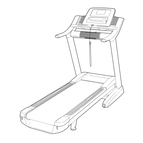
- Page 5 BEFORE YOU BEGIN Thank you for selecting the revolutionary NordicTrack ® ing this manual, please see the front cover of this man- COMMERCIAL 1750 treadmill. The COMMERCIAL ual. To help us assist you, please note the product 1750 treadmill offers an impressive selection of fea- model number and serial number before contacting us.
- Page 6 ASSEMBLY Assembly requires two persons. Set the treadmill in a cleared area and remove all packing materials. Do not dispose of the packing materials until assembly is completed. Note: The underside of the treadmill walking belt is coated with high-performance lubricant.
- Page 7 Make sure that the power cord is unplugged. Place a piece of cardboard below the rear of the Frame (56) to protect the floor or carpet. Attach the Left Wheel Cap (96) to the Base (97) with two #8 x 3/4" Screws (1). Attach the Right Wheel Cap (not shown) to the right side of the Base (97) in the same way.
- Page 8 Holdthe LeftUpright ( 89)against t heBase (97).Becarefulnot to pinch the wires.If nec- essary, p osition theBaseGround Wire(94)in theholeinthesideoftheLeftUpright. I nsert two3/8"x 2 3/4"Bolts(7)andtwo3/8"x 1 1/4" Bolts(8)withtwo3/8"StarWashers (12)into theLeftUpright. Partially tighten the3/8"x2 3/4"Bolts(7)and the3/8"x 1 1/4"Bolts(8)untiltheheads ofthe BoltstouchtheLeftUpright ( 89); d o not fully tightenthe Boltsyet.
- Page 9 Withthe helpofa second person, h oldthecon- soleassembly n eartheLeftUpright ( 89). Connect theUpright W ire(84)totheconsole Console wire.Seethe inset drawing. The connectors Assembly should slide together easily and snap into place. If they do not, turn one connector and try again. IF YOU DO NOT CONNECT THE CON- NECTORS PROPERLY, THE CONSOLE MAY BECOME DAMAGED WHEN YOU TURN ON THE POWER.
- Page 10 Identify the Left Handrail (87), which is marked with a "Left" sticker. Slide the Left Handrail be- Console tween the console assembly and the pulse assembly. Assembly Pulse Assembly Attach the Left Handrail (87) with two 5/16" x 2" Bolts (4), a 5/16" x 3 3/4" Bolt (2), and three 5/16"...
- Page 11 10. Make sure there is a piece of cardboard below the rear of the Frame (56). IMPORTANT: Make sure to follow all instructions IMPORTANT: See page 14 and plug in the in this step power cord. Next, see page 16 and turn on the power.
- Page 12 12. Remove the packaging material from the bottom of the Frame (56). See the inset drawing. Make sure that the 1/2" Rear Foot Nuts (111) are threaded all the way onto the Rear Feet (60). Turn the two Rear Feet all the way into the Frame.
- Page 13 HOW TO USE THE CHEST PULSE SENSOR HOW TO PUT ON THE CHEST PULSE SENSOR may remain activated longer than necessary, drain- ing the battery prematurely. The chest pulse sensor consists of two components: the chest strap and the sensor unit. Insert the tab on o Store the chest pulse sensor in a warm, dry place.
- Page 14 OPERATION AND ADJUSTMENT THE PRE-LUBRICATED WALKING BELT dance with all local codes and ordinances. IMPORTANT: The treadmill is not compatible with Your treadmill features a walking belt coated with high- GFCI-equipped outlets and may not be compatible performance lubricant. IMPORTANT: Never apply sil- with AFCl-equipped outlets.
- Page 15 CONSOLE _mFD DIAGRAM 00000000-0_0_ 00000000 0000000000 0000000000 0000000000 0000000000 0000000000 0000000000 0000000000 0000000000 0000000000 0000000000 0000000000 0000000000 0000000000 "-4 0000000000 0000000000 0000000000 0000000000 0000000000 0000000000 0000000000 0000000000 0000000000 0000000000 0000000000 0000000000 0000000000 0000000000 0000000000 0000000000 0000000000 WARNING _.,_,. _r ,k FEATURES OF THE CONSOLE You can also listen to your favorite workout music or audio books with the console's premium stereo sound...
- Page 16 HOW TO TURN ON THE POWER HOW TO USE THE MANUAL MODE iMPORTANT: if the treadmill has been exposed to Insert the key into the console. cold temperatures, allow it to warm to room tem- See HOW TO TURN ON THE POWER at the left. perature before turning on the power, if you do not...
- Page 17 If you press one of the numbered 1 Step Speed - The distance that you have walked or run buttons, the walking belt will gradually change - The incline level of the treadmill speed until it reaches the selected speed setting. To select a speed setting that includes a decimal-- such as 3.5 mph--press two numbered buttons in...
- Page 18 To reset the console, press the iFit Menu button in handrails for approximately ten seconds--avoid the upper right corner of the screen. To pause the moving your hands. When your pulse is detected, workout, press the Pause button. To continue the your heart rate will be shown.
- Page 19 HOW TO USE A SET-A-GOAL WORKOUT The workout will continue until you reach the goal that you set. The walking belt will then slow to a Insert the key into the console. stop, and a workout summary will appear on the screen.
- Page 20 HOW TO USE A CALORIE BURN WORKOUT OR Press the Profile button at the top of the screen AN ALL-TERRAIN TRAILS WORKOUT near the time display to view a profile of the incline settings of the workout. To return to the map, press Insert the key into the console.
- Page 21 workout. The actual number of calories that The workout will continue in this way until the last segment ends. The walking belt will then slow to a you burn will depend on your weight, in addi- stop. A workout summary will then appear on the tion, if you manually change the speed or in- screen.
- Page 22 HOW TO USE THE IFIT LIVE MODE IFIT LIVE FCC INFORMATION The iFit Live mode enables the treadmill to communi- IMPORTANT: To comply with FCC and IC RF expo- cate with your wireless network. With the iFit Live sure compliance requirements, the antenna used mode, you can download personalized workouts, cre-...
- Page 23 HOW TO USE THE SETTINGS MODE #+= button, To return to the letter keyboard, press the ABC button. To capitalize a character, press The console features a settings mode that allows you the button with an upward-facing arrow. To clear to connect your treadmill to your own wireless network the last character, press the button with a back- and to log in to your iFit Live account.
- Page 24 Log in to your iFit Live account. Press the Back button to return to the settings mode. To log in to a different iFit Live account, touch the iFit Live Login button. Then, enter your user name Turn on or turn off the display demo mode. and password using the keyboard on the screen.
- Page 25 HOW TO USE THE MAINTENANCE MODE press the Begin button, the treadmill will automati- cally rise to the maximum incline level, lower to the The console features a maintenance mode that allows minimum incline level and then return to the start- you to calibrate the incline and speed of the treadmill, ing position.
- Page 26 Perform a network test. Press the Firmware Update button. Press the Begin button to check for updates or the Cancel button to return to the maintenance mode. If desired, press the Network Test button to check the connection status of the treadmill. The previous router status shows whether the treadmill has ever If you press the Begin button, a status bar will ap- connected to a wireless router.
- Page 27 HOW TO USE THE STEREO SOUND SYSTEM If you are using a personal CD player and the CD skips, set the CD player on the floor or another flat sur- face instead of on the console. To play music or audio books through the console's speakers, you must connect your MP3 player, CD player, or other personal audio player to the console.
- Page 28 HOW TO FOLD AND MOVE THE TREADMILL HOW TO FOLD THE TREADMILL HOW TO MOVE THE TREADMILL To avoid damaging the treadmill, adjust the incline Before moving the treadmill, fold it as described at the left. CAUTION: Make sure that the latch knob is to 0 percent before you fold the treadmill.
- Page 29 TROUBLESHOOTING Most treadmill problems can be solved by following the simple steps below. Find the symptom that applies, and follow the steps listed, if further assistance is needed, see the front cover of this manual. PROBLEM: The power does not turn on SOLUTION: a.
- Page 30 Lower the treadmill (see HOW TO LOWER THE TREADMILL FOR USE on page 28). Remove the three #8 x 3/4" Screws (1). Carefully pivot the Motor Hood (71) off. Locate the Reed Switch (52) and the Magnet (50) on the left side of the Pulley (49). Turn the Pulley View until the Magnet is aligned with the Reed Switch.
- Page 31 PROBLEM: The walking belt is off-center or slips when walked on SOLUTION: a. If the walking belt is off-center, first remove the key and UNPLUG THE POWER CORD. If the walking belt has shifted to the left, use the hex key to turn the left idler roller bolt clockwise 1/2 of a turn;...
- Page 32 EXERCISE GUiDELiNES Burning Fat--To burn fat effectively, you must exer- cise at a low intensity level for a sustained period of time, During the first few minutes of exercise, your body uses carbohydrate calories for energy. Only after the first few minutes of exercise does your body begin to use stored fat calories for energy, If your goal is to burn fat, adjust the intensity of your exercise until your heart rate is near the lowest number in your training...
- Page 33 SUGGESTED STRETCHES The correct form for several basic stretches is shown at the right. Move slowly as you stretch--never bounce. 1. Toe Touch Stretch Stand with your knees bent slightly and slowly bend forward from your hips. Allow your back and shoulders to relax as you reach down toward your toes as far as possible.
- Page 34 PART LIST Model No. NTL14010.1 R0111A To locate the parts listed below, see the EXPLODED DRAWING near the end of this manual. Key No. Qty. Description Key No. Qty. Description #8 x 3/4" Screw Reed Switch Clamp 5/16" x 3 3/4" Bolt Reed Switch 3/8"...
- Page 35 Key No. Qty. Description Key No. Qty. Description Wheel Pulse Bar Top Console Base Pulse Ground Wire Console Pulse Bar Bottom Module Housing 1/2" Rear Foot Nut Fan Assembly Hex Key Handrail Spacer 3/8" Flat Washer Console Frame User's Manual Note: Specifications are subject to change without notice.
- Page 37 EXPLODED DRAWING Model No. NTL14010.1 R0111A...
- Page 38 EXPLODED DRAWING Model No. NTL14010.1 R0111A i'!- 101 113 98_13 @-_34...
- Page 39 EXPLODED DRAWING Model No. NTL14010.1 R0111A...
- Page 40 ORDERING REPLACEMENT PARTS To order replacement parts, please see the front cover of this manual. To help us assist you, be prepared to pro- vide the following information when contacting us: o the model number and serial number of the product (see the front cover of this manual) o the name of the product (see the front cover of this manual) o the key number and description of the replacement part(s) (see the PART LIST and the EXPLODED DRAWING near the end of this manual)