Advertisement
Table of Contents
Operator's Manual
Snow Thrower
Models
E600E,
$610E,
E6COF
$640F,
E640E,
E640F
E640G,
E660F, E660G
IMPORTANT: READSAFETYRULES AND INSTRUCTIONS CAREFULLY
Warning:
This unit is equipped with an internal combustion engine and should not be used on or near any unimproved forest-covered,
brush-covered
or grass-covered
land unless the engine's exhaust system is equipped with a spark arrester meeting applicable local or state
laws (if any). If a spark arrester is used, it should be maintained in effective working order by the operator. In the State of California the
above is required by law (Section 4442 of the California
Public Resources Code). Other states may have similar laws. Federal laws apply
on federal lands. A spark arrester for the muffler is available through your nearest engine authorized service dealer or contact the service
department,
P.O. Box 361131 Cleveland, Ohio 44136-9722.
MTD LLC, P.O.BOX361131CLEVELAND, OHIO44136-9722
PRINTED IN U.S.A.
FORM
NO. 769-00292A
(5/2003)
Advertisement
Table of Contents

Related Manuals for MTD E600E


Summary of Contents for MTD E600E
- Page 1 Public Resources Code). Other states may have similar laws. Federal laws apply on federal lands. A spark arrester for the muffler is available through your nearest engine authorized service dealer or contact the service department, P.O. Box 361131 Cleveland, Ohio 44136-9722. MTD LLC, P.O.BOX361131CLEVELAND, OHIO44136-9722 FORM NO. 769-00292A (5/2003)
-
Page 2: Table Of Contents
TABLEOFCONTENTS Content Page Important Safe Operation Practices ................ Hardware Pack ......................Assembling Your Snow Thrower ................Know Your Snow Thrower ..................Operating Your Snow Thrower ................Making Adjustments ....................Maintaining Your Snow Thrower ................Service ........................Off-Season Storage ....................Troubleshooting ...................... -
Page 3: Important Safe Operation Practices
SECTION 1: IMPORTANT SAFEOPERATION P RACTICES This symbol points out important safety instructions, which if not followed, could endanger the personal safety and/or property of yourself and others. Read and follow all instructions in this manual before attempting to operate this machine. Failure to comply with these instructions may result in personal injury. - Page 4 4. Never operate withamissing ordamaged discharge Contact your d ealer ortelephone 1-800-800-7310 chute. Keep a llsafety d evices i nplace and working. assistance and thename o fyour n earest servicing dealer. 5. Never runanengine i ndoors orinapoorly v entilated area. E ngine exhaust contains carbon m onoxide, an odorless and deadly gas.
-
Page 5: Hardware Pack
SECTION2: CONTENTSOFHARDWARE PACK(Boxed Unit) Lay out the hardware according to the illustration for identification purposes. Part numbers are shown in parentheses. (Hardware pack may contain extra items which are not used on your unit.) ATTACHING THE HANDLES ATTACHING THE CHUTE ASSEMBLY Hex Bolts 5/16-18 x 2"... -
Page 6: Assembling Your Snow Thrower
SECTION 3: ASSEMBLING YOUR SNOW THROWER NOTE: This Operator's Manual covers several models. Right and Left Handles Snow thrower features vary by model. Not all Handle Panel Assembly features discussed in this manual are applicable to all Chute Assembly snow thrower models. Chute Directional Control Assembly Shift Rod Hardware Pack... - Page 7 Secure theupper handle andlowerhandle withthe Assembly (Boxed Unit) twoplastic wingknobs, c upped washers and Assembly Tip: For convenience in assembly, remove carriage bolt(eyebolt ontheleftside)previously the chute from the carton and lay it on top of the engine. removed. SeeFigure 4. Do not unwrap the chute till you have installed the handle panel and the clutch cables.
- Page 8 Thread the coupling end of the cable onto the threaded portion of the "Z" fitting until the rubber bumper (located on the underside of the clutch lever) only lightly contacts the upper handle. Cupped IMPORTANT:The cable should have very little slack, but should NOT be tight.
- Page 9 After assembling all three chute flange keepers, tighten, then back off 1/4 turn to allow easier movement of the chute. Use two 7/16" wrenches. Chute Attaching ChuteDirectional C ontrol Hairpin irectional (Hardware Group D) Control Clip_ • Thread one hex nut about halfway onto eye bolt on the chute directional control.
-
Page 10: Know Your Snow Thrower
Lower Handle Hairpin Lamp Wire Alternator Lead -Shift Rod Shift Arm Assembly Clip Figure 13 If your unit is not equipped with a lamp, contact Figure 12 Customer Support as instructed on page 2 for information regarding price and availability. LampWiring(IfEquipped) Snow Thrower Model Electric Light Kit... -
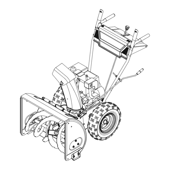
Page 11: Operating Your Snow Thrower
Shift Lever Traction/Auger Control Lock --------_ Auger Control Discharge Chute ._Spark Plug Choke Chute Clean-out Tool Recoil Starter Handle Chute Directional Control Cl°sed7 Ignition Key Throttle Control Auger Fuel Shut-Off Valve Figure 14 Chute Clean-0ut T001 NOTE: Do NOT 'turn" the ignition key in an attempt to start the engine. - Page 12 Attach spark plug wire to spark plug. Make certain • If your home wiring system is not a three-wire the metal loop on end of the spark plug wire (inside grounded system, do not use this electric starter the boot) is fastened securely over the metal tip on under any conditions.
- Page 13 ToEngage Drive • With the engine running near top speed, move shift lever into one of the five FORWARD positions or two REVERSE positions. Select a speed appropriate for the snow conditions that exist. Use the slower speeds until you are familiar with the "Z"...
-
Page 14: Making Adjustments
Drift Cutters If your unit is not equipped with drift cutters, contact (Optional Equipment) Customer Support as instructed on page 2 for Drift cutters should be used when operating the snow information regarding price and availability. thrower in heavy drift conditions. Snow Thrower Model Drift Cutter Kit On models so equipped, drift cutters are assembled to... - Page 15 ShiftRod Frame Cover To adjust the shift rod, proceed as follows. • Remove the hairpin clip and flat washer from the shift handle under the handle panel. • Place shift lever in sixth (6) position or the fastest forward speed. •...
-
Page 16: Maintaining Your Snow Thrower
Adjust skid shoes by loosening the four hex nuts and carriage bolts and moving skid shoes to desired position. Make certain the entire bottom surface of skid shoe is against the ground to avoid Inside Hole in Axle uneven wear on the skid shoes. Retighten nuts and bolts securely. -
Page 17: Service
Shear Bolts Chain Lever oil on Gear Shaft friction wheel and drive plate Bearings Bearings Figure 24 Figure 23 Wheels AugerShaft • Oil or spray lubricant into bearings at least once a • At least once a season, remove shear bolts on season. - Page 18 ShavePlateandSkidShoes • Drain the gasoline from the snow thrower, or place a piece of plastic under the gas cap. The shave plate and skid shoes on the bottom of the • Tip the snow thrower up and forward so that it rests snow thrower are subject to wear.
- Page 19 • Drain the gasoline from the snow thrower, or place Friction a piece of plastic under the gas cap. Wheel • Tip the snow thrower up and forward, so that it rests on the housing. See Figure 18. • Remove the six self-tapping screws from the frame cover underneath the snow thrower.
-
Page 20: Off-Season Storage
SECTION 9: OFF-SEASON S TORAGE • Remove all dirt from exterior of engine and WARNING: Never store engine with fuel in equipment. tank indoors or in enclosed, poorly ventilated • Follow lubrication recommendations on page 16. areas where fuel fumes may reach an open flame, spark or pilot light as on a furnace, NOTE: When storing any type of power equipment in water heater,... -
Page 21: Parts List
SECTION 11: PARTS LIST REF. PART DESCRIPTION 618-0123 RH Reducer Housing 618-0124 LH Reducer Housing 710-0642 Hex Screw 1/4-20 x.75 711-0908A Spiral Axle 24" 711-0909A Spiral Axle 26" 711-0910A Spiral Axle 28" 714-0161 715-0143 Pin-Spiral 717-0528 Worm Gear, 20T 717-0526 Worm Shaft 718-0186 Thrust Collar... - Page 22 ModelsE6OOE, $610E,E640E,E640F,$640F,E640G,E660F,E6COF & E660G 10 8. 17 ----_j_ ! 731-...
- Page 23 ModelsE6OOE, $610E,E640E,E640F,$640F,E640G,E660F,E6COF & E660G REF. PART REF. PART DESCRIPTION DESCRIPTION 714-0507 Cotter Pin 720-0201A Chute Knob - Black 747-0877 720-04031 Chute Knob - Yellow 710-0599 Hex Washer Screw 1/4-20 x.5 731-1392 Panel (w/tamp cut-out) 784-5680 705-5204A Chute Crank Handle Support Bracket - RH 784-5679 747-0697 Handle Support Bracket - LH...
- Page 24 ModelsE6OOE, $610E,E640E,E640F,$640F,E640G,E660F,E6COF & E660G Drive Clutch Cable Auger Clutch Cable 40 / Auger Clutch Cable...
- Page 25 ModelsE6OOE, $610E,E640E,E640F,$640F,E640G,E660F,E6COF & E660G REF. PART REF. PART DESCRIPTION DESCRIPTION 710-1652 717-04094 7-Tooth Shaft Self-tapping Screw, 1/4-20 x.625 784-5688 Drive Cable Guide Bracket 715-0249 Roll Pin 784-5687A 714-0143 Ktik Pin Auger Clutch Cable Bracket 756-0625 Cable Roller 684-0042C Friction Wheel Assembly 738-0924 Hex Screw 1/4-28 656-0012A...
- Page 26 ModelsE6OOE, $610E,E640E,E640F,$640F,E640G,E660F,E6COF & E660G 451- REF. PART REF. PART DESCRIPTION DESCRIPTION 712-0116 Lock Jam Nut 3/8-24 712-0798 Hex Nut 3/8-16 756-0178 Flat Idler 784-5580 Snow Shoe 784-5632B Chute Clean-out Tool Auger Idler Arm 731-2643 710-0459A Hex Cap Screw 3/8-24 x 1.50 731-2635 Mount, Chute Clean-out Tool 738-0281...
- Page 27 ModelsE6OOE, $610E,E640E,E640F,$640F,E640G,E660F,E6COF & E660G IMPORTANT: For a proper working machine, use Factory Approved Parts. V-BELTS are specially designed to engage and disengage safely. A substitute (non OEM) V-Be t can be dangerous by not d sengag ng comp ete y. 16 19"_ PART REF.
- Page 28 MANUFACTURER'S LIMITED WARRANTY FOR: ® The limited warranty set forth below is given by MTD LLC with MTD LLC does not extend any warranty for products respect to new merchandise purchased and used in the sold or exported outside of the United States, its posses- United States, its possessions and territories.