Table of Contents
Advertisement
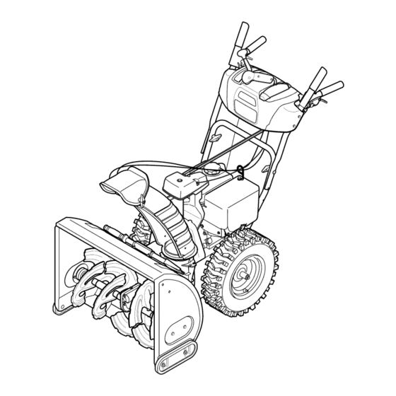
Operator's
Manual
CRRFr MRN
26" SNOW THROWER
Model No. 247.886912
CAUTION:
Before
using
this product,
read this
manual
and follow
all
safety
rules
and operating
instructions.
o SAFETY
ASSEMBLY
OPERATION
MAINTENANCE
PARTS LIST
o ESPANOL
Sears Brands Management
Corporation,
Hoffman Estates, IL 60179, U.S.A.
Visit our website:
www.craftsman.com
FORMNO. 769-05134E
7/26/2011
Advertisement
Table of Contents

Related Manuals for Craftsman 247.886912


Summary of Contents for Craftsman 247.886912
- Page 1 SAFETY ASSEMBLY OPERATION MAINTENANCE PARTS LIST CAUTION: Before using o ESPANOL this product, read this manual and follow safety rules and operating instructions. Sears Brands Management Corporation, Hoffman Estates, IL 60179, U.S.A. Visit our website: www.craftsman.com FORMNO. 769-05134E 7/26/2011...
-
Page 2: Specifications
This warranty isvoid ifthis product isever used w hile providing commercial services orifrented toanother person. w arrantycoverage details to obtain repairor replacement, v isit the website: www.craftsman.com This warranty covers ONLYdefects in material and workmanship. Warranty coverage does NOT include: •... - Page 3 This machinewas builtto be operatedaccordingto the safeopera- This symbolpointsout importantsafetyinstructionswhich,if not tion practicesin this manual.As with anytype of powerequipment, followed,couldendangerthepersonalsafetyand/orpropertyof carelessnessor error on the partof the operatorcan resultin serious yourselfand others. Readand followall instructionsin this manual injury.This machineis capableof amputatingfingers,hands,toes beforeattemptingto operatethis machine.Failureto complywith and feet and throwingdebris.Failureto observethe followingsafety these instructionsmay resultin personalinjury.Whenyou seethis...
- Page 4 Safe Handling of Gasoline • Exerciseextremecautionwhenoperatingon or crossinggravel surfaces.Stay alertfor hidden hazardsor traffic. Toavoidpersonalinjuryor propertydamageuseextremecare in handlinggasoline.Gasolineis extremelyflammableand the vaporsare • Exercisecautionwhenchangingdirectionand whileoperatingon explosive.Seriouspersonalinjurycan occurwhengasolineis spilled slopes.Do notoperateon steep slopes. on yourselfor yourclotheswhichcan ignite.Washyour skin and • Planyoursnow-throwing patternto avoiddischargetowards changeclothesimmediately.
- Page 5 MAINTENANCE & STORAGE DO NOT MODIFY ENGINE • Nevertamperwith safetydevices.Checktheirproperoperation Toavoidseriousinjuryor death,do not modifyengine in any way. regularly.Referto the maintenance and adjustmentsectionsof Tampering with the governorsettingcanlead to a runawayengineand this manual. cause it to operateat unsafespeeds.Nevertamperwithfactory setting of engine governor. •...
- Page 6 SAFETY SYMBOLS This pagedepictsand describessafetysymbolsthat mayappear on this product. Read,understand,and followall instructionson the machine beforeattemptingto assembleand operate. READ THE OPERATOR'S MANUAL(S) Read, understand, and follow all instructions in the manual(s) before attempting to assemble operate WARNING-- ROTATING BLADES Keep hands out of inlet and discharge openings while machine is running.
- Page 7 Thispage leftintentionally blank.
- Page 8 NOTE:References to rightor left sideof the snowthrowerare determined from behindthe unit in the operatingposition(standing directlybehindthe snow thrower,facingthe handlepanel). Chute Control Head REMOVING FROM CARTON _ort Cut the cornersof thecarton and lay the sidesflat on the ground. Bracket Removeand discard all packinginserts. Movethe snowthrowerout of thecarton.
- Page 9 Placechuteontochute baseand ensurechutecontrol rod is Chute Controlf positionedunder handlepanel.Installhex boltpreviouslyremoved but do notsecurewith wing nutat this time.See Figure4. Squeezethetriggeron the handlepaneljoystickand rotatethe chute byhand to face forward.The holesin the chutecontrol inputwill be facing up. See Figure5. NOTE:The chutewill not rotatewithoutsqueezing the triggeron the joystick.
- Page 10 7. Makesureall cablesare routedto the left of thechute control rod.Line up the hole in the rod with thearrowon the inputshaft and insertthe end of the rod into the inputshaftbelowjoystickon handlepanel.See Figure7. NOTE:Thechute controlrod will fit snugglyintothe inputshaft. Supportthe rear of thedash panelwith one handwhileinsertingthe rod with yourotherhandto ensurethe rod is insertedall the way into the input shaft.
- Page 11 10. Checkthat all cables are properlyroutedthroughthecable guide "_ on theengine.See Figure10. NOTE:If the chute controlis not assembledcorrectlyit will not move freelynor will it movefully to the rightand left. 11. Theextensioncord forthe electricstarteris fastenedwith a cabletie to the rearof the auger housingfor shippingpurposes. Cutthe cabletie and removecord beforeoperatingthe unit.
- Page 12 Chute Clean=Out Tool A chute clean-out tool is fastenedto the top of the augerhousing with a mountingclip. See Figure12.The tool is designedto cleara chuteassemblyof ice and snow.This item is fastenedwith a cabletie at the factory.Cut thecable tie beforeoperatingthe snowthrower. Chutedean=out Tool loft _1 .allmovingpartshave stoppedbeforeusingthe clean-outtool to clearthe chuteassembly.
- Page 13 Priorto operatingyoursnowthrower,carefullyread and followall instructionsbelow.Performall adjustments to verifyyoursnow throweris operatingsafelyand properly. Checktheadjustmentof the augercontrolas follows: Whentheauger controlis releasedand in the disengaged"up" position,the cableshouldhavevery little slack. It shouldNOTbe tight. In a well-ventilated area,start the snowthrowerengine.Referto Startingthe Enginein the Operationsection. Whilestandingin the operator'sposition(behindthe snow thrower),engagethe augers.
- Page 14 Shift Lever Drive Control z Four=Way ChuteControP (Joystick) Auger Control Gas Cap ... WheelSteeringControl ChuteAssembly \\\\ Muffler Recoil Starter Clean Out .d e Primer Tool Fill Throttle Control Choke Control :lectric Start Button Oil Drain Electric Starter Outlet Skid Shoe Augers Figure15 Nowthat youhaveset up yoursnowthrower,it's importantto become...
- Page 15 THROTTLE CONTROL The augercontrol is locatedon the left handle.Squeezethe control grip againstthe handleto engagethe augerand startsnowthrowing action.Releaseto stop. DRIVE CONTROL/AUGER CONTROL LOCK Thethrottlecontrolis locatedon the rearof the engine.It regulatesthe DRIVE speedof theengine and will shutoff the enginewhenmovedintothe CONTROL STOPposition. RECOIL STARTER HANDLE This handleis usedto manuallystartthe engine.
- Page 16 CLEAN-OUT TOOL • Refuelin a well-ventilated area with the enginestopped.Do not smokeor allowflamesor sparksin the areawherethe engineis refueledor wheregasolineisstored. • Donot overfillthe fueltank.After refueling,makesurethe tank Neveruseyourhandsto cleara cloggedchuteassembly.Shut cap is closed properlyand securely. loft engineand remainbehindhandlesuntil all movingparts have • Be carefulnotto spillfuel whenrefueling.Spilledfuel or fuel vapor lstopped beforeusingtheclean-outtool to clearthe chuteassembly.
- Page 17 TO ENGAGE DRIVE Movethrottlecontrolto FAST(rabbit)_J_" position. With the throttlecontrolin the Fast(rabbit) position,moveshift Movechoketo the CHOKE I,'_1 position(coldenginestart). If leverinto one of the six forward(F) positionsor two reverse(R) engineis warm,placechokein RUNposition. positions.Selecta speedappropriatefor the snowconditionsand Pushprimerthree (3) times, makingsureto covervent hole in a paceyou'recomfortable with.
- Page 18 MAINTENANCE SCHEDULE Before performing anytype ofmaintenance/service, disengage all Followthe maintenance schedulegiven below.This chart describes controls and stoptheengine. W aituntilall moving partshavecometo serviceguidelinesonly. Usethe ServiceLog columnto keeptrackof a completestop.Disconnect sparkplugwireandgroundit against t he completedmaintenance tasks.To locate the nearest Sears Service enginetoprevent u nintended starting. A lwayswearsafety glassesduring Centeror to scheduleservice,simplycontactSearsat 1-800-4-MY-HOME®.
- Page 19 Reinstallthe drain plugand tightenit securely. Refillwith the recommended oil and checkthe oil level.See Recommended Oil Usagechart.Theengine'soil capacityis 20 ounces. (%-40 °-20 o 0o 200 400 Oil Drain ("c) -300 -200 -10° 0° Plug DO NOTuse nondetergent o il or 2-strokeengineoil. It could shorten the engine'sservicelife.
- Page 20 hot a nd can ine. LUBRICATION Gear Shaft Thegear (hex)shaft shouldbe lubricatedat least oncea seasonor afterevery 25 hoursof operation. Topreventspillage,removeall fuel fromtank by runningengine until it stops. Carefullypivotthe snowthrowerup and forwardso that it restson theauger housing. X" "?X Removethe lowerframecover fromthe undersideof the snow / ..
- Page 21 ADJUSTMENTS Shift Cable If thefull rangeof speeds(forwardand reverse)cannotbe achieved, referto the figureto the rightand adjustthe shift cableas follows: Placethe shiftleverin thefastest forward speedposition(F6). Loosenthe hex nuton the shiftcable indexbracket.See Figure Pivotthe bracketdownwardto take up slack in the cable. Retightenthehex nut. Drive Control Whenthedrivecontrol is releasedand in thedisengaged"up"position, the cableshouldhavevery little slack.It shouldNOTbe tight.
- Page 22 Auger Control "_ Referto the Assemblysectionfor instructions on adjustingtheauger controlcable. Skid Shoes Referto the Assemblysectionfor instructions on adjustingthe skid shoes. BELT REPLACEMENT Auger Belt To removeand replaceyoursnow thrower'sauger belt, proceedas follows: Topreventspillage,removeall fuel fromtank by runningengine until itstops. Removethe plasticbelt coveron the front of the engineby remov- Figure27 ing the two self-tappingscrews.See Figure27.
- Page 23 7. Remove the belt f rom around the auger pulley, and slip the belt between thesupport bracket and the auger pulley. See Figure 31. 8. Reassemble auger belt b yfollowing these i nstructions inopposite order and manner ofremoval. 9. Perform t he Auger Control test o utlined inthe Assembly section ofthis manual.
- Page 24 If the snowthrowerwillnot be usedfor30 daysor longer,or if it is the end of the snowseasonwhenthe last possibilityof snowis gone,the equipmentneedsto be storedproperly.Followstorageinstructionsbelowto ensuretop performance from the snowthrowerfor manymoreyears. PREPARING SNOW THROWER PREPARING ENGINE Whenstoringthe snowthrowerin an unventilatedor metal stor- Enginesstoredover30 days need to be drainedof fuel to prevent age shed,careshouldbe taken to rustprooftheequipment.Using deterioration and gumfrom formingin fuel systemor on essential a light oil or silicone,coat theequipment,especiallyanychains,...
- Page 25 Enginefails to start Chokecontrolnot in CHOKEposition. Movechokecontrolto CHOKEposition. Sparkplugwire disconnected. Connectwireto sparkplug. Faultysparkplug. Clean,adjustgap,or replace. Fueltank emptyor stalefuel. Filltank with clean,freshgasoline. Enginenot primed. Primeengineas instructedin the OperationSection. Keynot inserted. Insertkeyfully intothe switch. Connectone end of the extensioncordto the electric Extensioncordnot connected(when usingelectricstartbutton,on modelsso starteroutletand the otherend to a three-prong equipped).
-
Page 26: Parts List
Craftsman Snow Thrower Model 247.886912... - Page 27 Craftsman Snow Thrower IViodel 247.886912 731-2635 SnowRemoval T oolMount 684-04107-0637 Spiral Assembly,LH 684-04108-0637 684-04057A-0637 ImpellerAssembly,12"Dia. Spiral Assembly,RH 731-04870 Spacer,1.25OD x .75ID x 1.00 L710-0347 L Hex Screw,3/8-16, 1.75,Gr5 710-0451 Bolt, Carriage,5/16-18,.750Grl 736-0188 Washer,Flat,.76x 1.49x .06 710-04484 Screw, 5/16-18,0.750 741-0493A Bushing,Flange,.80ID x .91OD...
- Page 28 Craftsman Snow Thrower Model 247.886912 t< Ij,...
- Page 29 Craftsman Snow Thrower Model 247.886912 684-04112B HandleEngagement A ssemblyRH 712-3087 Wing Nut, 1/4-20 714-04040 BowTie CotterPin 738-04367 FlangeShoulderScrew LockPlate 731-04894D 710-0262 CarriageBolt,5/16-18x 1.50 684-04250 PivotRod 631-04133A HandleClutchLock LHAssembly 935-0199A RubberBumper 684-04111B HandleEngagement A ssemblyLH 784-5594-0637 Cable Bracket 710-3069 Screw,1/4-20x .500...
- Page 30 Craftsman Snow Thrower IViodel 247.886912 _dJg_, i_o_ F_ _\\'_v/_ "_/'_ i"_ i4o;...
- Page 31 O ¸ 710-1652 AB Screw,1/4-20x 0.625 684-04159 FrictionWheelAssembly 731-05353 BeltCover 716-0136 RetainerRing 735-04099 Plug,3/8 ID 726-0221 Speed Nut 711-1268B ActuatorShaft 790-00183B-0637 WheelDrive Frame 746-04229B DriveClutchCable 756-04109 Auger Pulley 736-0505 FiatWasher 732-04345 ExtensionSpring 790-00207B DriveClutchCableGuideBracket 738-04439 ShoulderScrew 936-0119 LockWasher 684-04156A Shift RodAssembly 750-04474 AxleSupportTube 684-04169...
- Page 32 Craftsman Engine IViodel 270=SU=11 For Snow IViodel 247.886912 951-11282 MufflerAssembly 710-04911 StudM8x36 951-10657 MufflerStudAssembly 951-11285 ExhaustPipe Gasket 712-04214 Nut,M8 951-11111 ExhaustPipe Shield 710-04914 Bolt M6xl0 710-04915 Bolt M6x12 951-10642A MufflerShield...
- Page 33 Craftsman Engine Model 270=SU=11 For Snow Model 247.886912 951-11897 Carburetor GasketPlate 951-11112 ChokeControl 951-10634 EngineShroud 712-04213 951-11284 ChokeKnob 951-10757 ThrottleControlKnob 951-10637 IgnitionSwitchAssembly 731-05632 951-10640 Choke PushRod 951-10635 HeaterBox 710-04919 Bolt M6x25...
- Page 34 Craftsman Engine IViodel 270=SU=11 For Snow IViodel 247.886912...
- Page 35 Craftsman Engine IViodel 270=SU=11 For Snow IViodel 247.886912 951-12111 PistonRingSet 951-11283 Oil FillPlugAssembly 951-11632 PistonPin Snap Ring 951-11577 O-Ring15.8x2.5 951-12007 Piston 951-11368 Oil Seal,25x41.25x6 951-11633 PistonPin 951-11249 CrankcaseKit 710-04915 Bolt M6x12 (Incl.61,64,76,77,81) 951-11113 Air Shield 951-11350 Oil DrainPipe Assy. 951-11573...
- Page 36 Craftsman Engine IViodel 270=SU-11 For Snow IViodel 247.886912...
- Page 37 Craftsman Engine IViodel 270=SU=11 For Snow IViodel 247.886912 710-04744 Bolt M6x16 951-11054A ValveCover 731-07059 BreatherHose 726-04101 Hose Clamp 951-11565 ValveCoverGasket 951-12000 Retainer,In.Valve Spring 951-11892 RockerArmAssembly 751-11124 Nut, PivotLocking 751-11123 AdjustingNut ,Valve 951-11893 RockerArm 710-04902 Bolt, Pivot 951-12002 Adjuster,ExhValve 951-12003 Retainer,Ex.Valve Spring...
- Page 38 Craftsman Engine IViodel 270=SU=11 For Snow IViodel 247.886912...
- Page 39 Craftsman Engine IViodel 270=SU=11 For Snow IViodel 247.886912 710-04939 Stud M6x117 710-04910 Stud M6x105 951-11567 CarburetorInsulatorGasket 951-11896 CarburetorInsulator 951-11569A CarburetorGasket 951-10639A PrimerAssembly 951-11824 PrimerBulb 951-10638A Carburetor Assembly 951-11897 CarburetorGasketPlate ChokeShaft ChokePlate ThrottleShaft ThrottlePlate Screw M3x5 Lock Washer Gasket,ThrottlePlate IdleJet Assembly...
- Page 40 Craftsman Engine IViodel 270-SU-11 For Snow IViodel 247.886912 _130 94 _ _'91 94.4 _95 951-10646 IgnitionCoil Assembly 951-11110 Air FlowShield 710-04940 BoltM6xlO 710-04919 BoltM6x25 951-12416 Flywheel 951-10909 Fan,Cooling 951-10911 Pulley,Starter 712-04209 Nut,Special,M14x1.5 710-04915 BoltM6x12 951-10663A BlowerHousing 736-04455 Gasket6 710-04974 BoltM6xlO...
- Page 41 Craftsman Engine IViodel 270=SU=11 For Snow IViodel 247.886912 951-10758 951-10662 ThrottleControlAssemlby Engine/ DipstickCover 710-04928 BoltM6x12 710-04905 Bolt 951-11108 710-04915 Bolt M6x12 GovernorSystemShield 951-11935 951-11381 GovernorSpring Oil FillTubeO-Ring 951-10664 951-11913 ThrottleLinkageSpring Oil FillTubeAssembly 951-10665 951-11904 ThrottleLinkage Dipstick O-Ring 951-11106 GovernorArm 951-12482...
- Page 42 Craftsman Engine Model 270=SU=11 For Snow Model 247.886912 777S33610 777122991 777123026 777122990 777122992...
- Page 43 Craftsman Snow Thrower Model 247.886912 777S32636 777D16339 l -- "1001 J.nO-NV3"IO 'WnNVI_ S,EIOIVEI3dO OV::IEI"_ •830v-I_ln8 13MEI9 NO9NIIV_GdO N:IHM NoIInVO VUIX;] :189'S_I:1QNVlSA8 IV :19HVHOSIQ 13:1HIQU:1A:1N 'S31HnFNI $103r80 NMOEIH.L OlOAV 01 "t "]NIH3WJ 9NIOIAEI]S EIO9NIOOOIONfl ::lUOd:19 Q]dd01S :IAVHS.LHVd9NIAOW TIP ]I.LNn S]IQNVH (]NIH]8 NIV_:1EIONV ':1NIgN:1d01S 'SEI:1A:1I H Olfl'13]9VgN]SIQ "£...
- Page 44 MTD CONSUMER GROUP INC (MTD), the California Air Resources Board (CARB) and the United States Environment Protection Agency (U. S. EPA) Emission Control System Warranty Statement (Owner's Defect Warranty Rights and Obligations) EMISSION CONTROLSYSTEM COVERAGE IS APPLICABLE TOCERTIFIEDENGINESPURCHASED IN CALIFORNIA IN 2005 ANDTHERE- AFTER,WHICHARE USEDIN CALIFORNIA, A NDTO CERTIFIED MODELYEAR2005 AND LATERENGINESWHICHARE PURCHASED AND USEDELSEWHERE IN THE UNITEDSTATES.
- Page 45 (4)Repair orreplacement ofany warranted part under the warranty provisions ofthis article m ust beperformed atnocharge tothe owner ata warranty station. (5)Notwithstanding the provisions ofSubsection (4) above, warranty services orrepairs must beprovided atallMTD distribution centers that are franchised toservice the subject engines. (6)The owner must not b echarged fordiagnostic labor that l eads tothe determination that a warranted...
- Page 46 Look For Relevant Emissions Durability Period and Air index information On Your Engine Emissions Label Engines that are certified to meet the California Air Resources Board (CARB) Tier 2 Emission Standards must display information regarding the Emissions Durability Period and the Air Index. Sears Brands Management Corporation makes this information available to the consumer on our emission...
- Page 47 Congratulations on making a smart purchase. Your new Craftsman® product is designed manufactured for years of dependable operation. But like all products, it may require repair from time to time. That's when having a Repair Protection Agreement can save you money and aggravation.
- Page 48 La presentegarantiase anula si se utilizaeste productoalguna vezpara prestarservicioscornerciales o si se Ioalquilaa otra persona. Paraobtener informaci6n sobre el alcance de la garantiay solieitar la reparaci6no el reemplazo, v isite el sitio Web: www.craftsman.com Esta garantia cubre0NICAMENTElos defectos en los rnateriales y en la rnano de obra. Esta garantia NOcubre: •...
- Page 49 Esta rn_.quina r ue construidapara seroperadade acuerdocon La presenciade este sfrnboloindicaque setrata de instrucciones las reglasde seguridadcontenidasen este manual.AI igualque irnportantesde seguridadque se deben respetarpara evitar concualquiertipo de equipo rnotorizado, u n descuidoo error por poner en peligrosu seguridadpersonaly/o materialy la de otras partedel operadorpuedeproducirlesionesgraves.Esta rn_.quina personas.Lea y siga todaslas instruccionesde este manualantes es capazde arnputarrnanosy piesy de arrojarobjetoscon gran...
- Page 50 Manejo seguro de la gasolina • Nuncaoperela rn_.quina si falta un rnontajedel canalo si el rnisrnoest,. daSado.Mantengatodos losdispositivosde seguri- Paraevitar lesiones personales 0 daSosrnateriales tengarnucho dad en su lugaryen funcionarniento. cuidadocuandotrabajecon gasolina.La gasolinaes surnarnente inflarnabley sus vaporespuedencausarexplosiones. S i se derrarna •...
- Page 51 • Paraencenderel motor,jale de la cuerdalentarnente hasta que • SegOn la Cornisi6nde Seguridad de Productosparael Consurni- sienta resistencia,luegojale r_.pidarnente. El replieguer_.pido de dor de los EstadosUnidos(CPSC)y la Agenciade Protecci6n la cuerdade arranque(tensi6nde retroceso)le jalar_,la rnanoy Arnbiental d e los EstadosUnidos(EPA),este productotieneuna el brazohaciael motor rn_.s r_.pido de Io que usted puedesoltar.
- Page 52 SiMBOLOS DE SEGURIDAD Esta p_ginadescribelossimbolosy figurasde seguridadinternacionales que puedenapareceren este producto.Lea el manualdel operador )araobtenerla informaci6n terminadasobreseguridad,reunirse,operaci6ny mantenimiento y reparaci6n. LEA EL MANUAL DEL OPERADOR (S) Lea, entienda, y siga todas las instrucciones en el manual (es) antes de intentar reunirse y funcionar.
- Page 53 NOTA:las referendasal lade derechoo y ciertosde la m_.quina quitanievese determinan desdela parteposteriorde la unidaden Cabezalde posM6n de operaci6n(permaneciendo directamente detr_.s de la Control clel m_.quina quitanieve,mirandohada el panelde la manija), Canal EXTRACCION DE LA UNIDAD DE LA CAJA de Soporte del Canal Corte lasesquinasde la cajade cart6ny exti_ndalaen el piso Quitey descartetodoslos insertos de empaque.
- Page 54 4. Ubique elcanal sobre l abase d el m ismo ygarantizar lavarilla h ex agonal est,. situado bajo elpanel manejar. Instalar elperno hexagonal previamente eliminado, pero n oseguro con tuerca de mariposa eneste momento. Vea lafigura 4 . 5. Apriete eldisparador enlapalanca decontrol ygire elcanal manualmente para q ue mire hacia d elante.
- Page 55 7. Inserte la varilla hexagonal dentro del engranaje del pih6n por debajo de la palanca de control. Asegurese de alinear el orificio en la varilla hexagonal con la flecha en el engranaje del piB6n. Vea la figura 7. NOTA:El orificioes una referenciaparaalinear la varillacon la flecha indicadoraen el engranaje del pi56n.
- Page 56 10. Controleque todos loscables est_nadecuadarnente dirigidosa "" " travesde la gufade cables en el motor.Veala figura 10. NOTA: Pararn_.s suavefuncionarniento, l os cablesdebenestar a la izquierdade la varillahexagonal. 11. El prolongadorparael arrancadorel_ctricose ajustarnediante una uni6n de cablea la parteposteriorde la cajade la barrena para el ernbarque.Corte la uni6nde cable y refirelaantesde operarla rn_.quina quitanieve.
- Page 57 Herramienta de Lirnpieza del Canal Hay una herrarnienta de lirnpiezadel canal iajustada a la parte superiorde la caja de la barrenaconun pasadorde ensarnNado.Vea la figura12.La herrarnienta est&diseSadaparalirnpiarel hMo y la nievedel rnontajede un canal. Este productose sujetarnedianteuna uni6nde cableen la f&brica.Corte la uni6nde cableantes de operar Herramienta la rnAquina quitanieve.
- Page 58 NOTA:Si tieneque usar la rn_.quina q uitanievesobregrava,rnantenga la zapata antideslizante en la posici6nrn_.s elevadapara Iograruna separaci6nrn_.xirna entreel pisoy la placade raspado. Paraajustar laszapatasantideslizantes: Aflojelas cuatrostuercashexagonales (dosen cada lado)y los pernosdel carro. Muevalas zapatasantideslizantes a la posici6n deseada.Vea la figura 13. Cornpruebe que toda la superficieinferiorde hs zapatas antideslizantes est_contra el sueloparaevitar un desgaste desparejode los rnisrnos.
- Page 59 Hay dosvelocidadesde retroceso(R). La uno (1) es la rn_.s lenta, y la dos (2) es larn_.s r_.pida. Curnple con los estandares de seguridad de ANSi Lasrn_.quinas q uitanievede Craftsman curnplen con losest_.ndares de seguridad del instituto estadounidense d e est_.ndares nacionales (ANSI).
- Page 60 CONTROL DEL REGULADOR CONTROL DE LA BARRENA F CONTROL LA BARRENA El controldel reguladorest,. ubicadoen la partetraseradel motor. Regulala velocidaddel motor,y Io apagacuandose Iocolocaen la posici6nSTOP(detenci6n). MANIJA DEL ARRANCADOR DE RETRO- CESO Esta rnanijase utiliza paraarrancarel motorrnanualrnente. El controlde la barrenaest,. ubicadoen la rnanijaizquierda.Aprietela BOTON DEL ARRANCADOR ELECTRICO...
- Page 61 RUEDA QUECONDUCE MANDOS Vuelvaa ajustar la herrarnienta de lirnpiezaal pasadorde en- sarnbladoubicadoen la parteposteriorde la cajade la barrena, La ruedaizquierday derechaque conducernandoses Iocalizadaen la insertede nuevola Ilavede encendidoy enciendael motorde la parteocultade los mangos.Aprieteel controlderechoparadar vuelta rn_.quina q uitanieve. a la derecha;aprieteel control izquierdopara dar vuelta a la izquierda. Parado en la posici6n deloperador (detr_.s d e la rn_.quina quita- nieve), e ngrane el control d e la barrena durante unossegundos para NOTA:Hagafuncionaral lanzadorde nieveen _.reas abiertashasta...
- Page 62 • No Ileneen excesoel tanquede combustible.Despu_sde cargar Determinesi el cableadode su hogares un sisternade tres cables conectadoa tierra.Consultecon un electricistarnatriculado si no est,. combustible, a segQrese de que el tap6ndel tanqueest_ bien cerradoy asegurado. seguro. • Tengacuidadode no derrarnarcombustibleal realizarla recarga. Si cuentacon un recept_.culo d e tres terrninales,sigalos siguientes El combustiblederrarnado o sus vaporesse puedenincendiar.
- Page 63 DETENCION DEL MOTOR Arrancador de retroceso Dejeencendidoel motordurantealgunosrninutosantesde detenerlo paraperrnitirque se sequela hurnedad en el rnisrno. I Notire de la rnanijadel arrancadorrnientras el motorest,. en rnarcha, I Muevael controldel regulador a la posici6nOFE Retirela Ilave.AI retirarla Ilavese reducela posibilidadde que el Muevala palancade controldel reguladora la posici6n FAST motorseapuestoen rnarchasinautorizaci6nrnientrasel equipo no est,.
- Page 64 LISTA DE iVlANTENIIVllENTO Antesde realizarcualquiertipodel rnantenirniento/servicio, suelte Siga la listade rnantenirniento dada abajo.Estacarta describepautas todoslos rnandosy pareel motor.Esperehasta que todaslas partes de servicios61o. U se la colurnnade Troncode Serviciopara guardar de rnovirniento hayanvenidoa una paradacornpleta.Desconecteel la pistade tareasde rnantenirniento cornpletadas. L ocalizarel rn_s alarnbrede bujiay b_selocontra el motor para prevenirel cornienzo cercanoCharnusca el Centrode Servicioo prograrnar el servicio,sirn- involuntario.
- Page 65 Cambio de aceite del motor NOTA:Carnbieel aceitedespu_sde las 5 prirnerashorasde operaci6ny despu_sde cada50 horasde operaci6no una vez por ternporada. Vacfeel combustibledel tanquehaciendofuncionarel motor hastaque el tanquede combustibleest_ vacfo.Cerci6resede que la tapadel combustibleest,. asegurada. Coloqueun recipiente adecuadopara recolectarel aceitebajo el tap6nde drenajede aceite. Retireel tap6nde drenajede aceite.Vea la Figura17.
- Page 66 Midala separaci6nde bujia con un calibrador.Corrijade ser necesariotorciendoel electrodolateral.Vea la Figura19.La separaci6n debe establecerseentre0,02y 0,03 pulgadas(0,60- Electrodo 0,80ram). Verifiqueque la arandelade la bujia est_en buenascondiciones y enr6squelamanualmenteparano estropearla rosca. Unavez que la bujfaest_ colocada,apri_telacon una Ilavepara comprimirla arandela. NOTA:Cuandoinstaieuna bujia nueva,una vez colocadala bujia apriete1/2vuelta paracomprimir[aarandela.Cuandovuelvaa co[ocar 0,02- 0,03 puigadas una bujfausada,una vez colocadala bujia apriete1/8- 1/4de vuelta...
- Page 67 NOTA:Laszapatasde esta m_.quina tienendos bordesde desgaste. Cuandoun lado se desgasta,se las puede rotar 1800 para usarel otro horde. Para retirarlas zapatasantideslizantes: Quitelos cuatropernosdel carro,arandelas(si corresponde),y las tuercasde brida hexagonales que losasegurana la m_.quina quitanieve. Montelas nuevaszapatasantideslizantes con cuatrospernos de carro (dosen cada lado),arandelas,y las tuercasde brida hexagonales.
- Page 68 Ubiquela rn_nsulahaciaarribapara brindarrn_.s juego (o hacia abajo paraaurnentarla tensi6ndel cable). Vuelvaa apretarla tuercahexagonalsuperiory repetirlos pasos la4. Varilla de control del canal ParaIograruna mayorengagrnent v arillahexagonal e n el pi56nde artes en el marcodel panel de rnanejar, e s necesarioajustar la varilla de controldel canal.Vea la figura25.
- Page 69 4. Gire con cuidado lam_.quina quitanieve hacia a rriba y hacia delante demanera que quede apoyada sobre l acaja dela barrena. 5. Saque lacubierta del m arco desde d ebajo delam_.quina quitanieve retirando los tornillos autorroscantes que laaseguran. Vea lafigura 2 8. 6.
- Page 70 3. a. Saque lacorrea delabarrena delapolea d el m otor. b. Tome l apolea I oca y gfrela h acia l aderecha. Vea lafigura c. Levante lacorrea delabarrena para sacarla delapolea d el motor. 4. Gire con cuidado larn_.quina quitanieve hacia a rriba y hacia delante dernanera que quede a poyada sobre l acaja dela barrena.
- Page 71 Si no sevaa utiliza el equipo durante30 dfaso rn_.s, o sies el finalde la ternporada de nievey ya noexisteposibilidad deque nieve, e s necesario alrnacenar e l equipo de rnanera adecuada. S igalasinstrucciones d e alrnacenarniento quese indicana continuaci6n p aragarantizar e l rendirniento rn_.xirno d e la rn_.quina q uitanieve durante rnuchos a_os.
- Page 72 El motorno arranca La palancade obturaci6nno est,. en la Pongael interruptor en la posici6nCHOKE(obtura- posici6nON (encendido) ci6n). Se ha desconectado el cablede la bujia Conecteel cablea la bujfa. La bujia nofunciona correctamente Limpie,ajustela distanciadisruptivao cambie. El tanquede combustibleest,. vado o el Lleneel tanquecongasolinalimpiay fresca.
- Page 73 Dernasiada vibraci6n Hay piezasque est_.n fiojas o la barrena Detengael motorde inrnediatoy desconecteel est,. dafiada cablede la bujia.Ajuste todoslos pernosy las tuercas.Si la vibraci6ncontinQa. I levela unidada reparara un centrode partesy reparaci6nSears. Perdidade potencia El cable de la bujfaest,. flojo Conectey ajusteel cablede la bujfa.
- Page 74 MTD CONSUMER GROUP, iNC. (MTD), el Bordo de Recursos de Aire de California (CARB) y la Agencia de Protecci6n Medioambiental de Estados Unidos (U. S. EPA) Declaraci6n de Garantia del Sistema de Control de Emisiones (Derechos y obligaciones del propietario seg_n la garantia contra defectos) LA COBERTURADESISTEMADECONTROLDEEMISIONES APLICABLE A MOTORES CERTIFICADOS COMPRADOS ENCALIFORNIA EN2005 Y A PARTIRDE ENTONCES, QUESON USADOS EN CALIFORNIA, Y HASTA ANO2005 DE MODELOCERTIFICADO Y MOTORES POSTERIORES QUESON COMPRADOS Y USADOSENOTRAPARTEEN LOSESTADOS UNIDOS.
- Page 75 reernplazada segQn lagarantia segarantizar_, por e lresto d el p eriodo degarantia. (3) Cualquier pieza g arantizada que est_ prograrnada para reernplazo segQn elrnantenirniento requerido deconforrnidad con lasinstruc- clones escritas delaSubsecci6n (c)segarantiza por e lperiodo detiernpo anterior alaprirnera fecha d ereernplazo prograrnada para e sa pieza.
- Page 76 Busque el periodo de duraci6n de emisiones importantes yla informaci6n de clasificaci6n de aire en la etiqueta de emisiones de su motor Los motores cuyo cumpiimiento con los estAndares de emisi6n Tier 2 de la Comisi6n de Recursos Ambientales de California (CARB) est6 certificado deben exhibir la informaci6n relacionada con el periodo de duraci6n de ias emisiones y la clasificaci6n de aire.
- Page 77 Felicitaciones por haber realizado una adquisici6n inteligente. El producto Craftsman® que ha adquirido esta diseSado y fabricado para brindar muchos aSos de funcionamiento confiable. Pero como todos los productos a veces puede requerir de reparaciones. Es en ese momento cuando...
- Page 80 Your Home For troubleshooting, product manuals and expert advice: managernylife www.managemylife.com For repair - in your home - of all major brand appliances, lawn and garden equipment, or heating and cooling systems, no matter who made it, no matter who sold it! For the replacement parts, accessories owner's manuals that you need to do-it-yourself.