Panasonic KX-VC500 Operating Manual
Hd visual communication unit
Hide thumbs
Also See for KX-VC500:
- Operating manual (142 pages) ,
- User manual (102 pages) ,
- Brochure (6 pages)
Table of Contents
Advertisement
Quick Links
Operating Manual
HD Visual Communication Unit
KX-VC500
Model No.
Thank you for purchasing a Panasonic HD Visual Communication Unit.
Please read this manual carefully before using this product and save this manual for future use.
KX-VC500: Software File Version 2.20 or later
In this manual, the suffix of each model number (e.g., KX-VC500NA) is omitted unless necessary.
Document Version: 2011-02
Advertisement
Table of Contents

Related Manuals for Panasonic KX-VC500


Summary of Contents for Panasonic KX-VC500
- Page 1 HD Visual Communication Unit KX-VC500 Model No. Thank you for purchasing a Panasonic HD Visual Communication Unit. Please read this manual carefully before using this product and save this manual for future use. KX-VC500: Software File Version 2.20 or later In this manual, the suffix of each model number (e.g., KX-VC500NA) is omitted unless necessary.
- Page 2 Introduction Introduction Feature Highlights Video camera Video camera Display Display Microphone Microphone Router Router Internet DCE: Data Circuit-terminating Equipment Lifelike Visual Communication You can experience lifelike visual communication with smooth, high-quality video and clear stereo sound. If using 2 or more microphones, stereo output can be enabled through system settings (only when Boundary Microphones are connected) (Page 79).
- Page 3 (Page 89). For details about the activation key, contact your dealer. Connection to non-Panasonic Video Conference Systems You can connect to a non-Panasonic video conference system and have a 2-party video conference call. This feature must be enabled with an activation key (Page 68, Page 89).
- Page 4 CD-ROM before using this product. Also, some software parts of this product are licensed under the MOZILLA PUBLIC LICENSE (MPL). At least three (3) years from delivery of products, Panasonic will give to any third party who contacts us at the contact information provided below, for a charge of no more than the cost of physically distributing source code, a complete machine-readable copy of the corresponding source code and the copyright notices covered under GPL, LGPL, and MPL.
- Page 5 Introduction Precaution Notice for users in California This product contains a CR coin cell lithium battery that contains perchlorate material—special handling may apply. See www.dtsc.ca.gov/hazardouswaste/perchlorate Document Version 2011-02 Operating Manual...
-
Page 6: Table Of Contents
Table of Contents Table of Contents For Your Safety ..................9 For Your Safety .........................9 Before Operation ..................13 Notes about Operation ....................13 Data Security ........................14 Privacy and Right of Publicity ..................14 Federal Communications Commission Requirements ..........15 Preparation .....................16 Part Names and Usage ....................16 Main Unit (Front) ......................16 Main Unit (Back) ......................17 Remote Control ......................18... - Page 7 Table of Contents About Enhanced Features ..............67 Activating Enhanced Features ..................67 Overview of Activation Keys ...................67 Enabling Connection to Non-Panasonic Video Conference Systems ......68 Enabling Connection to an MCU ..................69 Contacts and Settings ................71 Adding Contacts to the Contact List ................71 Registering a New Contact .....................71...
- Page 8 Table of Contents Specifications ..................113 System Specifications ....................113 Index......................114 Operating Manual Document Version 2011-02...
-
Page 9: For Your Safety
For Your Safety For Your Safety For Your Safety WARNING To prevent personal injury and/or damage to property, be sure to observe the following safety precautions. General The following symbols classify and describe the Follow all warnings and instructions level of hazard and injury caused when this unit is marked on the unit. - Page 10 For Your Safety Operating Safeguards To prevent fires, electric shock, injury, or damage to the unit, be sure to follow Do not disassemble this unit. Only these guidelines when performing any qualified personnel should service this wiring or cabling: unit. Disassembling the unit may expose Before performing any wiring or you to dangerous voltages or other risks.
- Page 11 For Your Safety Battery Unplug the unit from the AC outlet and have it serviced by qualified service The battery contains diluted sulfuric personnel in the following cases: acid, a very toxic substance. If the If the unit does not operate battery leaks and the liquid inside spills according to the operating on the skin or clothing, immediately...
- Page 12 For Your Safety This product contains batteries. Replace CAUTION only with the same or equivalent type. Improper use or replacement may cause overheating, rupture or explosion Power resulting in injury or fire. Dispose of used When the unit is not used over an batteries according to the instructions of extended period of time, take the your local solid waste officials and local...
-
Page 13: Before Operation
Before Operation Notes about Operation Avoid placing the device in areas with high Before Operation humidity, and exposing it to rain. Neither the main unit nor the power plug is water Please pay attention to the following points when using resistant. -
Page 14: Data Security
By installing and using this device, you are responsible Panasonic is not responsible for any damages for maintaining the privacy and usage rights of images caused by improper use of this device. -
Page 15: Federal Communications Commission Requirements
Before Operation Federal Communications Commission Requirements Federal Communications Commission Interference Statement This equipment has been tested and found to comply with the limits for a Class A digital device, pursuant to Part 15 of the FCC Rules. These limits are designed to provide reasonable protection against harmful interference when the equipment is operated in a commercial environment. -
Page 16: Preparation
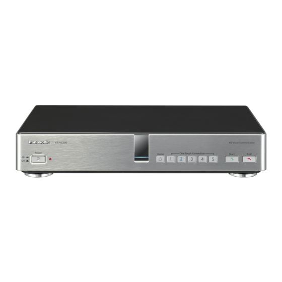
Preparation Part Names and Usage Preparation Main Unit (Front) Power LED Shows the power status. The LED is red when the power is on and off when the power is off. Remote Control Signal Receiver Receives Remote Control signals. The maximum range of reception is approximately 8 m (26.2 ft) from front of the unit, and approximately 3 m (9.8 ft) from 20°... -
Page 17: Main Unit (Back)
Preparation Main Unit (Back) RS-232C terminal This terminal is not available for use. MIC jack (Page 22) Used to connect the Boundary Microphone (optional) (Page 19). Audio In L/R jack (Page 22) Used to connect general-purpose microphones (not for the Boundary Microphone). LAN jack (Page 22) Connect a LAN cable. -
Page 18: Remote Control
Preparation Remote Control Press to show the sub video camera’s images on your and the other party’s display during a video conference call. When not on a video conference call, the sub video camera’s images are shown on your display only (Page 60). Press to show your computer’s Press to display/hide information screen on your and the other party’s... -
Page 19: Boundary Microphone (Optional Accessory)
Preparation Boundary Microphone (Optional Accessory) Boundary Microphone (Proprietary cable included. Cable length: approx. 8.5 m [approx. 28 ft]) Part No.: KX-VCA001 MIC Mute button Press to mute your own voice so that other video conference call participants cannot hear you (Page 52). -
Page 20: Led Patterns
Preparation LED Patterns LEDs indicate the operational status of the unit, as follows: LED pattern Status Slow blue flashing • Starting up • Idle state Blue on • In a video conference call (including when dialing, receiving a video conference call, and being disconnected) Orange on •... - Page 21 Preparation • It takes about 7 seconds to return from screen standby mode. (The length of time may vary depending on the type of display you are using.) Document Version 2011-02 Operating Manual...
-
Page 22: Connecting The Unit
Preparation Connecting the Unit Note • If your display is not compatible with HDMI, use a component cable (Page 25). Since This section describes how to connect the main video sound signals are not transmitted when camera, display, microphone, LAN cable and power using a component cable, connect an cord. - Page 23 (Page 79). • If you are connected to an MCU or non-Panasonic video conference system, the output sent to the other party will be monaural. Layout examples (the grey circle indicates the microphone’s range): Display (13.1 ft)
- Page 24 Preparation Noise 40 dBsplA 45 dBsplA 50 dBsplA level/ (a quiet (a regular (a noisy Micro– room) room) room) phone Display (13.1 ft) approx. approx. approx. Microphone (13.1 ft) 2.2 m 1.2 m (approx. (approx. (approx. Microphone 9.8 ft) 7.2 ft) 3.9 ft) (13.1 ft) approx.
- Page 25 Preparation Amplifier/Active Speaker Connecting the Display with a Connection Component Cable This section describes how to connect an amplifier/ If your display does not have an HDMI terminal, use a active speaker. component cable for connection. Connect the display to the Component terminal on the back of the unit using a component cable.
-
Page 26: Turning The Power On/Off
Preparation Turning the Power On/Off Note • Make sure that peripheral devices (e.g., display, main video camera) are turned on. Press the [Power] button on the front of the unit. • The Power LED and all of the One-Touch Connection button LEDs turn on. Then, the One-Touch Connection button LEDs turn off, the Status LED starts flashing blue slowly, and the Home screen is displayed. -
Page 27: Screen Display
Preparation Screen Display Home Screen (Idle Screen) Displayed when the power is turned on. Also displayed when the [Home] button is pressed on the unit or on the remote control. Main Video Camera Image Displays the video from the main video camera. Unit Information Displays the unit’s name, IP address, maximum bandwidth and encryption status. -
Page 28: Menu Screen (Idle Screen)
Preparation Icon Status LAN cable or peripheral connection error (no connection, device error, etc.). Note • If the MIC detection setting has been disabled through system settings (Page 78), the icon will not be displayed even if the Boundary Microphone is disconnected. -
Page 29: Video Conference Call Screen
Preparation Video Conference Call Screen Other party’s information When registered in the contact list: The other party’s name/group name is displayed. When not registered in the contact list: The other party’s IP address or host name (e.g., www.example.com) is displayed. Video Image Displays the other party’s video, your own video, or video from the secondary video input such as a computer display or a sub video camera (Page 55, Page 59). - Page 30 Preparation Note • Pressing [Full Screen] on the remote control will hide or unhide the other party’s information, duration, network status indication , and guide displays. If the network status indication has been set to not be displayed, pressing [Full Screen] will not show the icon. Operating Manual Document Version 2011-02...
-
Page 31: Starting A Video Conference
3-party/4-party video conference calls may not be possible depending on bandwidth settings (Page 77, Page 91). • When connecting to non-Panasonic video conference systems, you can make only 2-party video conference calls. Calling Using Speed Dial (2-party Conference/3-party Conference/ 4-party Conference) Note •... - Page 32 Starting a Video Conference Calling from the Home Screen (Operation with the Main Unit) Press [Home]. • The Home screen is displayed. Press [One-Touch Connection] (1 to 5). • The LED for the One-Touch Connection number you pressed lights up. •...
- Page 33 Starting a Video Conference Calling from the Menu Screen (Operation with the Remote Control) Note • From the Menu screen, you can make a video conference call using up to 300 speed dial numbers (1 to 300). (From the Home screen, you can make a video conference call using up to 5 One-Touch Connection numbers [1 to 5].) Press [Menu].
-
Page 34: Calling From The Contact List (2-Party Conference/3-Party Conference/4-Party Conference)
Starting a Video Conference Calling from the Contact List (2-party Conference/3-party Conference/4-party Conference) Press [Menu]. • The Menu screen is displayed. Select "Contact List" using [ ] and press [Enter]. • The contact list screen is displayed. The entries are 2, 3 grouped in the index tabs and displayed in alphabetical order of "Group/Site". - Page 35 Starting a Video Conference Press [Start] to start the call. When you want to end the call, press [End]. • The Home screen is displayed. Document Version 2011-02 Operating Manual...
-
Page 36: Calling By Entering An Ip Address
Starting a Video Conference Calling by Entering an IP Address You can make a video conference call by entering the IP address of the party you want to call. Press [Menu]. • The Menu screen is displayed. Select "Manual Dial" using [ ] and press [Enter]. - Page 37 • IP addresses will be cleared if you move to another input screen without pressing [Start]. • When connecting to an MCU or non-Panasonic video conference system, you cannot make 3-party/ 4-party video conference calls. Enter the IP address. •...
-
Page 38: Calling From The Call History
• 2-party/3-party/4-party video conference calls can be made using the outgoing call history. • When connecting to non-Panasonic video conference systems, you can make only 2-party video conference calls using the outgoing call history. • For video conference calls made using the contact list, the contact name is displayed. For video conference calls made by entering the IP address directly (Page 36), the IP address is displayed. - Page 39 Starting a Video Conference Press [Menu]. • The Menu screen is displayed. Select "Call History" using [ ] and press [Enter]. • The outgoing call history screen is displayed. 2, 3 Note • The result of the video conference call is displayed in the "Call result"...
- Page 40 Starting a Video Conference Select the party you want to call using [ Note • If you press [Enter], the call history details screen is displayed. • When not selecting a local site (Page 92), "Local site name" will be blank. •...
-
Page 41: Answering A Video Conference Call
Starting a Video Conference Answering a Video Conference Call Depending on your setting, you can either respond to a request to participate in a video conference call manually (manual answer) or automatically (automatic answer) (Page 77). Note • Make sure that peripheral devices (e.g., display, main video camera) are turned on. When Manual Answer is Set When a video conference call is incoming there will be an incoming call ring, and a dialog box is displayed. - Page 42 Starting a Video Conference When Automatic Answer is Set When a video conference call is incoming the call will be automatically answered after one ring, and transmission then begins. Operating Manual Document Version 2011-02...
-
Page 43: Changing The Screen Layout
Changing the Screen Layout Changing the Screen Layout during a 2-party Video Conference Call You can choose from 3 different screen layouts when taking part in a 2-party video conference call. Press [Layout]. • The screen will cycle through the available layouts each time you press [Layout]. - Page 44 [R]: The screen layout will be switched to Layout 1. • When using a secondary video source (Page 55, Page 59), the screen layout cannot be changed. (You can change the screen layout when connecting to an MCU or non-Panasonic video conference system.) •...
-
Page 45: Changing The Screen Layout During A 3-Party Video Conference Call
Changing the Screen Layout Changing the Screen Layout during a 3-party Video Conference Call You can choose from 7 different screen layouts when taking part in a 3-party (This Site, Site 1, Site 2) video conference call. Press [Layout]. • The screen will cycle through the available layouts each time you press [Layout]. - Page 46 Changing the Screen Layout Layout 1 Layout 2 Layout 7 Layout 3 Layout 6 Layout 4 Layout 5 A: Site 1 B: Site 2 C: This Site Operating Manual Document Version 2011-02...
- Page 47 Changing the Screen Layout Note • You can press [B], [R], or [G] to switch the screen layout to that button’s pre-assigned layout. layout displayed by each button depends on the screen layout currently in use. You cannot switch the screen layout to Layout 2 directly. However, you can switch to Layout 2 if you press [Layout] first (Page 45).
-
Page 48: Changing The Screen Layout During A 4-Party Video Conference Call
Changing the Screen Layout Changing the Screen Layout during a 4-party Video Conference Call You can choose from 6 different screen layouts when taking part in a 4-party (This Site, Site 1, Site 2, Site 3) video conference call. Press [Layout]. •... - Page 49 Changing the Screen Layout Layout 1 Layout 2*¹ Layout 6 Layout 3 Layout 5 Layout 4 A: Site 1 B: Site 2 C: Site 3 D: This site Image edges are trimmed and the image is centered. Note • You can press [B], [R], or [G] to switch the screen layout to that button’s pre-assigned layout. The layout displayed by each button depends on the screen layout currently in use.
- Page 50 Changing the Screen Layout Display Screen Layout Remote sites Layout 1 All Sites Layout 2 Site 1 Layout 3 Site 2 Layout 4 Site 3 Layout 5 This Site Layout 6 Example: When using Layout 3 [B]: The screen layout will be switched to Layout 1. [R]: The screen layout will be switched to Layout 2.
-
Page 51: Adjusting The Volume And Tone
Adjusting the Volume and Tone Adjusting the Volume You can adjust the volume during a video conference call. Press [Volume (+/–)]. • The volume level bar is displayed at the bottom of the screen. Adjust the volume using [Volume (+/–)]. •... -
Page 52: Muting The Microphone
Adjusting the Volume and Tone Muting the Microphone During a video conference call, you can mute the microphone so that your voice cannot be heard by the other party. You will be able to hear the other party’s voice, but they will not be able to hear you. Note •... -
Page 53: Reducing Microphone Noise
Adjusting the Volume and Tone Reducing Microphone Noise You can reduce the amount of ambient noise picked up by the microphone (shuffling of papers, etc.) during a video conference call. When noise reduction is in effect, the volume level of voices may also be reduced. Press [Y]. -
Page 54: Adjusting The Tone
After a video conference call is finished, the tone setting returns to the value set before starting the call. • When connecting to an MCU or non-Panasonic video conference system, the tone is set to "Standard" and cannot be changed. Operating Manual... -
Page 55: Displaying Other Video Sources
Displaying Other Video Sources Displaying a Computer’s Screen You can display a computer’s screen on your display and to other parties by connecting the computer to the unit. This is convenient when explaining something on the computer’s screen while showing it to others, for example. Main video camera Computer Router... - Page 56 Note • When connecting to an MCU or non-Panasonic video conference system, the same screen may not be shown on the other party’s display depending on the other party’s screen layout. Ask the other party to change their screen layout to display your computer’s screen.
- Page 57 Layout 1. To return to displaying your computer’s screen, press [B]. • When connecting to an MCU or non-Panasonic video conference system: – Even while displaying your computer’s screen, note that it is also possible for the other party to start sharing their computer’s...
- Page 58 Displaying Other Video Sources Note • On the Home screen, you can also display the computer’s screen on your display by pressing [PC]. While the computer’s screen is displayed, the unit will not enter screen standby mode. To return to the Home screen, press [Camera Main].
-
Page 59: Displaying The Sub Video Camera's Image
Displaying Other Video Sources Displaying the Sub Video Camera’s Image When a sub video camera is connected to the unit, you can display the sub video camera’s image on your display and to other parties. Main video camera Sub video camera Router Internet DCE: Data Circuit-terminating Equipment... - Page 60 Note • When connecting to an MCU or non-Panasonic video conference system, the same image may not be shown on the other party’s display depending on the other party’s screen layout. Ask the other party to change their screen layout to display your sub video camera’s image.
- Page 61 Layout 1. To return to displaying your sub video camera’s image, press [B]. • When connecting to an MCU or non-Panasonic video conference system: – Even while displaying your sub video camera’s image, note that it is also possible...
- Page 62 Displaying Other Video Sources Note • On the Home screen, you can also display the sub video camera’s image on your display by pressing [Camera Sub]. While the sub video camera’s image is displayed, the unit will not enter screen standby mode.
- Page 63 Note • Fix your sub video camera and the object so that the image is not blurred. • You cannot perform this operation when connecting to an MCU or non-Panasonic video conference system. Press [Camera Sub]. • The sub video camera’s image is displayed.
-
Page 64: Displaying The Connection Status
Displaying the Connection Status Displaying the Connection Status You can confirm the connection status of the network and peripheral devices. Press [Status]. • The connections status screen is displayed. An "X" mark is displayed next to any network or peripheral devices connection that is not in normal operation or not connected. -
Page 65: Displaying Unit Information
This information is not displayed when communication is not occurring. • Features activated due to software enhancement (Page 89) are displayed in "Software version". The details are as follows: "(CE)": Connection to MCUs and non-Panasonic video conference systems is available. Document Version 2011-02 Operating Manual... - Page 66 "Site 1", "Site 2" and "Site 3". *1*2 "Frequency" is not displayed when connecting to an MCU or non-Panasonic video conference system. Depending on the other party, "Name" may be blank. Press [Back]. • The display returns to the screen in use before the step 1 was performed.
-
Page 67: About Enhanced Features
Model No. Activation Key Type Description KX-VCS101 Connection Enhancement Enables the connection to MCUs and non-Panasonic video conference systems. Note • Once you have activated new features (Page 89), they remain activated even after software updates or a system initialization. -
Page 68: Enabling Connection To Non-Panasonic Video Conference Systems
About Enhanced Features Enabling Connection to Non-Panasonic Video Conference Systems You can connect to a non-Panasonic video conference system and have a 2-party video conference call. Intranet Note • To connect to non-Panasonic video conference systems, you must purchase an activation key card (KX-VCS101) and activate this feature beforehand (Page 89). -
Page 69: Enabling Connection To An Mcu
About Enhanced Features Enabling Connection to an MCU Connecting to an MCU allows you to have a video conference call with 5 or more parties. Intranet Note • To connect to an MCU, you must purchase an activation key card (KX-VCS101) and activate this feature beforehand (Page 89). - Page 70 Doing so allows you to operate (e.g., change the screen layout) the MCU remotely. Note • Tone signals can only be sent when connecting to an MCU. They cannot be sent between Panasonic HD Visual Communication Units. • Features and operations that can be performed remotely will vary depending on the MCU.
-
Page 71: Contacts And Settings
Contacts and Settings Adding Contacts to the Use [ ] to select the following items for input: Contacts and Settings "Group/Site": Enter a name for the contact (up to Contact List 24 characters) (Page 94). "Speed Dial": Enter a speed dial number (1–300). "Multi-Point": Use [ ] to select "No". -
Page 72: Editing Contact Information
Contacts and Settings Use [ ] to select the following items for input: Press [Enter]. "Group/Site": Enter a name for the video • conference call (up to 24 characters) (Page 94). The contact list details screen is displayed. "Speed Dial": Enter a speed dial number (1–300). Press [G]. -
Page 73: Registering A Contact From The Call History
Contacts and Settings Use [ ] to select "Contact List" and press Use [ ] to select "Call History" and press [Enter]. [Enter]. • • The contact list screen is displayed. The outgoing call history screen is displayed. Note • To refer to the incoming call history, press [G]. - Page 74 Contacts and Settings Note • When you register a multiple-party contact to the contact list from the call history, each party is also registered automatically as a single-party contact and each IP address is registered in "Group/Site". • If a host name is displayed in the "Site" column of the call history, the party cannot be registered in your contact list.
-
Page 75: Changing System Settings
Contacts and Settings Changing System Setting the Date and Time Settings Press [Menu]. • The Menu screen is displayed. Note Use [ ] to select "Settings" and press • If a video conference call is received while data [Enter]. is being entered, the data entry is interrupted •... -
Page 76: Making Sound Settings
Contacts and Settings Use [ ] to select "Settings" and press Use [ ] to select "Sound Settings" and press [Enter]. [Enter]. • • The system settings screen is displayed. The sound settings screen is displayed. Use [ ] to select "Network Settings" and press [Enter]. -
Page 77: Making Connection Settings
• When connecting to an MCU or Use [ ] to select the following items for input: non-Panasonic video conference system, set "Encryption" to "OFF" because • The following items are displayed over 2 pages. encryption is not available. Encryption must To view all the items, press [R] to move to the be disabled on both sides. -
Page 78: Display Unit Information
Contacts and Settings (This mode switches the display resolution "MIC detection": Use [ ] to select whether to according to the condition of the network.) enable the detection of the connection status of the – "Auto" (default): This mode selects either "Full Boundary Microphones. -
Page 79: Setting The Mic Position
Contacts and Settings Press [Menu]. Press [ • The Menu screen is displayed. • The second page is displayed. Use [ ] to select "Settings" and press Use [ ] to select "MIC Setting" and press [Enter]. [Enter]. • The system settings screen is displayed. •... - Page 80 Contacts and Settings Use [ ] to select "Settings" and press displayed as viewed from the side of the main video camera. [Enter]. • The system settings screen is displayed. Here are examples of the relative position of Boundary Microphones. When setting Boundary Microphones in a row Press [ perpendicular to the display:...
-
Page 81: Making Remote Control Settings
Contacts and Settings When setting Boundary Microphones as Making Remote Control follows: Settings Display Main video camera You can specify a remote control ID from 1, 2, or 3 for Speaker Speaker both the remote control and the unit. The unit responds to signals from any remote control with the same remote control ID as itself. -
Page 82: Performing A Network Test
Contacts and Settings • When "ON" is selected, if the unit receives a Use the following procedure to change the ID of the signal from a remote control that has an ID remote control. different from the one specified on the Home Press and hold [·] and [#] at the same time. -
Page 83: Performing Self Diagnosis
Contacts and Settings Use [ ] to select "Network Test" and press Press [ [Enter]. • The second page is displayed. • The network test screen is displayed. Use [ ] to select "Self Diag." and press [Enter]. • The self diagnosis screen is displayed with the dialog box. -
Page 84: Performing Remote Maintenance
Contacts and Settings Note Making Administrator • If you do not press [R], the self diagnosis Menu Settings will automatically end after about 10 minutes. Note Press [Home]. • If a video conference call is received while data • The Home screen is displayed. is being entered, data entry is interrupted and any unsaved data is lost. -
Page 85: Making Language Settings
Contacts and Settings Use [ ] to select "Login" and press [Enter]. Use [ ] to select "Yes" and press [Enter]. • • The admin menu screen is displayed. The admin menu screen is displayed in the selected language. Press [Home]. •... -
Page 86: Making Software Update Settings
This setting is available only when "Admin" is selected for "Access mode". • When connecting to an MCU or non-Panasonic video conference system, set "Encryption" to "OFF" because Use [ ] to select the following items for input: encryption is not available. Encryption must "DNS Server Addr.": Enter the IP address of the... -
Page 87: Updating Software
Contacts and Settings Press [G]. Use [ ] to select "Update Software Now" • A dialog box to confirm the saving of settings is and press [Enter]. displayed. • A dialog box to confirm the updating of your software is displayed. Use [ ] to select "Yes"... -
Page 88: Making Screen Standby Settings
Contacts and Settings Note Use [ ] to select "Standby Setting" and press [Enter]. • Contact your dealer for more information on • The screen standby settings screen is obtaining the latest firmware and Operating displayed. Manual. • If the checking, downloading, or installing of a software update fails, an error message is displayed. -
Page 89: Performing System Initialization
Contacts and Settings Use [ ] to select "Password Settings" and Use [ ] to select "System Initialize" and press [Enter]. press [Enter]. • • The password settings screen is displayed. A dialog box to confirm the start of system initialization is displayed. - Page 90 The software enhancement screen is are displayed in "Activated Features", as displayed. Check the field "MPR ID" (A). follows: – "Connection Enhancement": Connection to MCUs and non-Panasonic video conference systems is available. – "None": No features have been activated. Press [G]. •...
-
Page 91: Making Local Site Settings
"Local site name": Enter a name for the local site. When connecting to an MCU or "IP Address": Enter an IP address. non-Panasonic video conference system, • set "Encryption" to "OFF" because If the IP address contains 1 or 2 digit numbers, encryption is not available. -
Page 92: Selecting A Local Site
Contacts and Settings (This mode switches the display resolution Use [ ] to select "Select local site" and according to the condition of the network.) press [Enter]. – "Auto" (default): This mode selects either "Full • The select local site screen is displayed. HD"... -
Page 93: Editing Local Site Information
Contacts and Settings Deleting Local Site Information Use [ ] to select "Yes" and press [Enter]. Press [Menu]. • The Home screen is displayed. • The Menu screen is displayed. Editing Local Site Information Use [ ] to select "Select local site" and press [Enter]. -
Page 94: Input
Input Inputting Letters and Numbers You can use the remote control to input letters and numbers. The following tables detail the characters and numbers that can be input. The language that can be input depends on which language is selected through system settings. Press the indicated button repeatedly to cycle through the characters and numbers assigned to that button until the character you want to input is displayed. - Page 95 Input Table 1 English Letter Mode Extended Character 1 Extended Character 2 (Western Europe) Mode (Eastern Europe) Mode Number Uppercase Lowercase Uppercase Lowercase Uppercase Lowercase Button Mode -preferred -preferred -preferred -preferred -preferred -preferred Mode Mode Mode Mode Mode Mode A À Á Â Ã Ä Å a à...
- Page 96 Input Table 2 French Letter Mode Extended Character 1 Extended Character 2 (Western Europe) Mode (Eastern Europe) Mode Number Uppercase Lowercase Uppercase Lowercase Uppercase Lowercase Button Mode -preferred -preferred -preferred -preferred -preferred -preferred Mode Mode Mode Mode Mode Mode A À Á Â Ã Ä Å a à...
- Page 97 Input Table 3 Spanish Letter Mode Extended Character 1 Extended Character 2 (Western Europe) Mode (Eastern Europe) Mode Number Uppercase Lowercase Uppercase Lowercase Uppercase Lowercase Button Mode -preferred -preferred -preferred -preferred -preferred -preferred Mode Mode Mode Mode Mode Mode A À Á Â Ã Ä Å a à...
- Page 98 Input Switching the Input Mode Each time [B] or [R] is pressed, the input mode will be switched in the following cycle: • [B]: letter mode ® number mode ® extended character 1 mode ® extended character 2 mode • [R]: lowercase-preferred mode ®...
-
Page 99: Miscellaneous
Miscellaneous Changing the Remote Control Batteries Open the cover. Take out the AA batteries. Insert new batteries (AA dry cell), minus side first, then close the cover. Document Version 2011-02 Operating Manual... -
Page 100: Cleaning The Unit
Miscellaneous Cleaning the Unit When cleaning the unit, make sure the power is off and all cables are unplugged. Cleaning the unit while the power is on may cause a malfunction. • Wipe the unit with a dry, soft cloth. When the unit is very dirty, first clean it with a neutral, household cleaning agent using a well-wrung, damp cloth. -
Page 101: Additional Information
→ Set the display to show images at full screen. properly. • When connecting to an MCU or non-Panasonic video conference system, the other party’s image may be trimmed, depending on the device used by the other party. → Contact your dealer. - Page 102 Additional Information Problem Cause and Solution Operation is unresponsive or • Cables or cords may not be connected properly. incorrect. → Check that all cables to the unit are connected properly (Page 17). • An error has occurred. → Turn off the unit and restart it. •...
- Page 103 There may be a problem with your communication lines. → Contact your dealer. • If you are trying to connect to an MCU or non-Panasonic video conference system, encryption is enabled on either your or the other party’s side. →...
- Page 104 "2.0 Mbps" or higher (Page 77, Page 91). → If you are trying to connect to an MCU or non-Panasonic video conference system, depending on the other party’s device, the image may be distorted due to lack of bandwidth. In this case, contact your dealer.
-
Page 105: Audio
Additional Information Audio Problem Cause and Solution • The other party cannot hear The microphone cable is not properly connected. your voice. → Check that the microphone is properly connected to the unit (Page 17). Perform self diagnosis, and check the performance of the microphones that are connected to the unit (Page 83). -
Page 106: System Settings
Additional Information Problem Cause and Solution Sound cuts out or echoes. • Adjustments to the environment immediately after a video conference call has begun may not yet have completed. → Immediately after a video conference call has begun, be sure to speak in turn with other parties. -
Page 107: If These Messages Appear
Additional Information If These Messages Appear Message Cause and Solution • Call FAILED. Encryption The encryption settings do not match those of the other party in a video settings (On/Off) must match. conference call. Please change the encryption → Change the encryption settings to match those of the other party setting on one side and try (Page 77, Page 85). - Page 108 Additional Information Message Cause and Solution Sub-Camera source is not • A cable or cord is not properly connected. compatible. → Check that all cables to the unit are connected properly (Page 17). • The signal input from the sub video camera is invalid. →...
- Page 109 Check the software version of all parties. Update the unit with the older software version so that the versions match. Call FAILED. "Connection • A connection is trying to be established with an MCU or non-Panasonic Enhancement" feature must video conference system even though the feature for connecting to be activated before MCUs or non-Panasonic systems has not been activated.
- Page 110 Additional Information Message Cause and Solution Received remote control ID • The remote control IDs of the unit and remote control do not match. (n1). VC500 current setting is → Follow the on-screen instructions to change the remote control ID of the (n2).
- Page 111 "60" is displayed for n. Then, the remaining time starts to decrease. Disconnected. • When connecting to an MCU or non-Panasonic video conference system, the video conference call was disconnected because encryption settings were enabled. → Disable encryption settings on both sides. •...
-
Page 112: Miscellaneous
Additional Information Miscellaneous Problem Cause and Solution • A standard definition (640 ´ 480p, 720 ´ 480p) video camera signal has "Safe Mode" is displayed on the screen. been detected. → Disconnect the video camera from the unit, and reset the unit by turning off its power, then turning it back on. -
Page 113: Specifications
Approx. 4 kg (approx. 8.8 lb) Power Consumption Standby: approx. 30 W Maximum: approx. 32 W Either output can be set through system settings (Page 79); only monaural is available when connecting to MCUs and non-Panasonic video conference systems. Document Version 2011-02 Operating Manual... -
Page 114: Index
Enabling Connection to an MCU Language, setting Enabling Connection to Non-Panasonic Video Conference LED Patterns Systems Local Site, setting Activation Key Activation Key for Connection to MCUs/Non-Panasonic Video Conference Systems (KX-VCS101) Making a Video Conference Call Administrator Password, setting MIC Position, setting Amplifier/Speaker Microphones... -
Page 115: Document Version 2011-02 Operating Manual
Index Unit Information, viewing 65, 78 Unit Name, setting Volume, adjusting Document Version 2011-02 Operating Manual... - Page 116 Copyright: This material is copyrighted by Panasonic System Networks Co., Ltd., and may be reproduced for internal use only. All other reproduction, in whole or in part, is prohibited without the written consent of Panasonic System Networks Co., Ltd. © Panasonic System Networks Co., Ltd. 2010...