Table of Contents

Related Manuals for Extreme Networks 200 Series


Summary of Contents for Extreme Networks 200 Series
- Page 1 Summit 200 Series Switch Installation and User Guide Software Version 7.1e0 Extreme Networks, Inc. 3585 Monroe Street Santa Clara, California 95051 (888) 257-3000 http://www.extremenetworks.com December, 2003 Part Number: 100149-00 Rev 02...
- Page 2 Chassis, SummitLink, SummitGbX, SummitRPS and the Extreme Networks logo are trademarks of Extreme Networks, Inc., which may be registered or pending registration in certain jurisdictions. The Extreme Turbodrive logo is a service mark of Extreme Networks, which may be registered or pending registration in certain jurisdictions. Specifications are subject to change without notice.
-
Page 3: Table Of Contents
Installing the Switch Rack Mounting Free-Standing Desktop Mounting of Multiple Switches Installing or Replacing a Mini-Gigabit Interface Connector (Mini-GBIC) Safety Information Preparing to Install or Replace a Mini-GBIC Removing and Inserting a Mini-GBIC Summit 200 Series Switch Installation and User Guide xiii... -
Page 4: Rfc 2236-Internet Group Management Protocol, Version
Summit 200 Series Switch Numerical Ranges Names Symbols Line-Editing Keys Command History Common Commands Configuring Management Access User Account Administrator Account Default Accounts Creating a Management Account Domain Name Service Client Services Checking Basic Connectivity Ping Traceroute Summit 200 Series Switch Installation and User Guide... - Page 5 Disabling Network Login Using EAPOL Flooding Using the Simple Network Time Protocol Configuring and Using SNTP SNTP Configuration Commands SNTP Example Chapter 6 Configuring Ports on a Switch Enabling and Disabling Switch Ports Summit 200 Series Switch Installation and User Guide Contents...
- Page 6 Chapter 8 Forwarding Database (FDB) Overview of the FDB FDB Contents FDB Entry Types How FDB Entries Get Added Associating a QoS Profile with an FDB Entry Configuring FDB Entries FDB Configuration Examples Summit 200 Series Switch Installation and User Guide...
- Page 7 Routing Access Policy Commands Chapter 10 Network Address Translation (NAT) Overview Internet IP Addressing Configuring VLANs for NAT NAT Modes Configuring NAT Configuring NAT Rules Creating NAT Rules Creating Static and Dynamic NAT Rules Summit 200 Series Switch Installation and User Guide Contents...
- Page 8 Access List Based Traffic Groupings MAC-Based Traffic Groupings Explicit Class of Service (802.1p and DiffServ) Traffic Groupings Configuring DiffServ Physical and Logical Groupings Verifying Configuration and Performance QoS Monitor Displaying QoS Profile Information viii Summit 200 Series Switch Installation and User Guide...
- Page 9 Configuring STP on the Switch STP Configuration Example Displaying STP Settings Disabling and Resetting STP Chapter 15 IP Unicast Routing Overview of IP Unicast Routing Router Interfaces Populating the Routing Table Subnet-Directed Broadcast Forwarding Summit 200 Series Switch Installation and User Guide Contents...
- Page 10 RIP Version 1 Versus RIP Version 2 Overview of OSPF Link-State Database Areas Point-to-Point Support Route Re-Distribution Configuring Route Re-Distribution OSPF Timers and Authentication Configuring RIP RIP Configuration Example Displaying RIP Settings Resetting and Disabling RIP Configuring OSPF Summit 200 Series Switch Installation and User Guide...
- Page 11 Using the Console for Managing the Stack Setting the Command Prompt Chapter 19 Using ExtremeWare Vista on the Summit 200 ExtremeWare Vista Overview Setting Up Your Browser Accessing ExtremeWare Vista Navigating within ExtremeWare Vista Browser Controls Summit 200 Series Switch Installation and User Guide Contents...
- Page 12 Logging Out of ExtremeWare Vista Appendix A Safety Information Important Safety Information Power Power Cord Connections Lithium Battery Appendix B Technical Specifications Summit 200-24 Switch Summit 200-48 Switch Appendix C Supported Standards Summit 200 Series Switch Installation and User Guide...
- Page 13 Accessing the BootROM menu Boot Option Commands Appendix E Troubleshooting LEDs Using the Command-Line Interface Port Configuration VLANs Debug Tracing TOP Command Contacting Extreme Technical Support Index Index of Commands Summit 200 Series Switch Installation and User Guide Contents xiii...
- Page 14 Contents Summit 200 Series Switch Installation and User Guide...
-
Page 15: Preface
This preface provides an overview of this guide, describes guide conventions, and lists other publications that may be useful. Introduction This guide provides the required information to install the Summit 200 series switch and configure the ExtremeWare ™ software running on the Summit 200 series switch. -
Page 16: Conventions
The publications related to this one are: • ExtremeWare Release Notes • Summit 200 Series Switch Release Notes Documentation for Extreme Networks products is available on the World Wide Web at the following location: • http://www.extremenetworks.com/ Summit 200 Series Switch Installation and User Guide... -
Page 17: Summit 200 Series Switch Overview
Summit 200 Series Switch Overview This chapter describes the features and functionality of the Summit 200 series switches: • Summit 200 Series Switches on page 15 • Summary of Features on page 15 • Summit 200-24 Switch Physical Features on page 16 •... -
Page 18: Summit 200-24 Switch Physical Features
• Traffic mirroring for ports Summit 200-24 Switch Physical Features The Summit 200-24 switch is a compact enclosure (see Figure 1) one rack unit in height (1.75 inches or 44.45 mm) that provides 24 autosensing 10BASE-T/100BASE-TX ports using RJ-45 connectors. It also... - Page 19 10/100Mbps Ethernet. The switch also has four Gigabit Ethernet uplink ports. These ports are labeled 25 and 26 on the front panel of the switch. Two of the ports are 10/100/1000BASE-T ports using RJ-45 connectors. The other two ports are unpopulated receptacles for mini-SFP GBICs, using optical fibers with LC connectors.
- Page 20 Full-Duplex The Summit 200-24 switch provides full-duplex support for all ports. Full-duplex allows frames to be transmitted and received simultaneously and, in effect, doubles the bandwidth available on a link. All 10/100 Mbps ports on the Summit 200-24 switch autonegotiate for half- or full-duplex operation.
-
Page 21: Summit 200-24 Switch Rear View
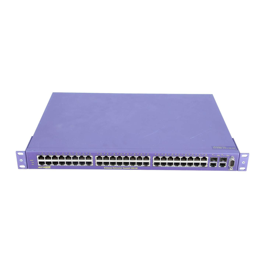
The Summit 200-24 switch certification and safety label is located on the bottom of the switch. Summit 200-48 Switch Physical Features The Summit 200-48 switch is a compact enclosure (see Figure 3) one rack unit in height (1.75 inches or 44.45 mm) that provides 48 autosensing 10BASE-T/100BASE-TX ports using RJ-45 connectors. It also... - Page 22 10/100Mbps Ethernet. The switch also has four Gigabit Ethernet uplink ports. These ports are labeled 49 and 50 on the front panel of the switch. Two of the ports are 10/100/1000BASE-T ports using RJ-45 connectors. The other two ports are unpopulated receptacles for mini-SFP GBICs, using optical fibers with LC connectors.
- Page 23 • To set up a redundant link on port 49, connect the active fibre and 1000BASE-T links to both the RJ-45 and mini-GBIC interfaces of port 49. The switch defaults to the fiber link. If the fiber link fails during operation, the switch automatically activates the redundant 1000BASE-T link.
-
Page 24: Summit 200-48 Switch Rear View
Figure 4 shows the rear view of the Summit 200-48 switch. Figure 4: Summit 200-48 switch rear view Power Socket The Summit 200-48 switch automatically adjusts to the supply voltage. The power supply operates down to 90 V. Power socket... -
Page 25: Mini-Gbic Type And Hardware/Software Support
The Summit 200-48 switch certification and safety label is located on the bottom of the switch. Mini-GBIC Type and Hardware/Software Support The Summit 200 series switch supports the SFP GBIC, also known as the mini-GBIC, in three types: the SX mini-GBIC, which conforms to the 1000BASE-SX standard, the LX mini-GBIC, which conforms to the 1000BASE-LX standard, and the ZX mini-GBIC, a long-haul mini-GBIC that conforms to the IEEE 802.3z... - Page 26 General Total system budget Total optical system budget for the SX mini-GBIC is 11.5 dB. Extreme Networks recommends that 3 dB of the total budget be reserved for losses induced by cable splices, connectors, and operating margin. While 8.5 dB remains available for cable-induced attenuation, the 1000BASE-SX standard specifies supported distances of 275 meters over 62.5 micron multimode fiber and 550 meters over 50 micron...
- Page 27 (for example 0.25 dB/km), Extreme Networks recommends that 3 dB of the total budget be reserved for losses induced by cable splices, connectors, and operating margin. Figure 5 shows the total optical system budget between long range GBICs in various end-to-end combinations (ZX, ZX Rev 03, LX70, and LX100).
- Page 28 6 dB 6 dB 0 dB 0 dB 9 dB 3 dB 3 dB 10 dB 4 dB 4 dB ZX mini 9 dB 8 dB 2 dB 5 dB 6 dB Summit 200 Series Switch Installation and User Guide...
-
Page 29: Switch Installation
Determining the Switch Location The Summit 200 series switch is suited for use in the office, where it can be free-standing or mounted in a standard 19-inch equipment rack. Alternately, the device can be rack-mounted in a wiring closet or equipment room. -
Page 30: Following Safety Information
Before installing or removing any components of the switch, or before carrying out any maintenance procedures, read the safety information provided in w of this guide. Installing the Switch The Summit 200 series switch switch can be mounted in a rack, or placed free-standing on a tabletop. Rack Mounting CAUTION Do not use the rack mount kits to suspend the switch from under a table or desk, or to attach the switch to a wall. -
Page 31: Free-Standing
Free-Standing The Summit 200 series switch is supplied with four self-adhesive rubber pads. Apply the pads to the underside of the device by sticking a pad in the marked area at each corner of the switch. Desktop Mounting of Multiple Switches You can physically place up to four Summit switches on top of one another. -
Page 32: Removing And Inserting A Mini-Gbic
NOTE If you see an amber blinking Mini-GBIC port status LED on your Summit 200 series switch, the mini-GBIC installed in your switch is one that is not approved or supported by Extreme Networks. To correct this problem, ensure that you install a mini-GBIC that is approved and supported by Extreme Networks. -
Page 33: Creating A Stack
However, these uplink ports may not be configured to be in a load share group. Load sharing is only supported for ports on the same switch. An example of a stacking configuration is shown in Figure 8. Summit 200 Series Switch Installation and User Guide... -
Page 34: Connecting Equipment To The Console Port
• Flow control—None NOTE If you set the switch console port flow control to XON/XOFF rather than None, you will be unable to access the switch. Do not set the switch console port flow control to XON/XOFF. The terminal connected to the console port on the switch must be configured with the same settings. - Page 35 Figure 10 shows the pin-outs for a 9-pin to 9-pin PC-AT null-modem serial cable. Figure 10: PC-AT serial null-modem cable pin-outs Summit Cable connector: 9-pin female Screen Shell Ground Summit 200 Series Switch Installation and User Guide Pin Number Direction — PC/Terminal Cable connector: 25-pin male/female Screen...
-
Page 36: Powering On The Switch
Turn the on/off switch to the on position. Checking the Installation After turning on power to the Summit 200 series switch, the device performs a Power On Self-Test (POST). During the POST, all ports are temporarily disabled, the port LED is off, and the MGMT LED flashes. - Page 37 7 When you are finished using the facility, logout of the switch by typing logout NOTE After two incorrect login attempts, the Summit 200 series switch locks you out of the login facility. You must wait a few minutes before attempting to log in again. Summit 200 Series Switch Installation and User Guide...
- Page 38 Switch Installation Summit 200 Series Switch Installation and User Guide...
-
Page 39: Summary Of Features
• Software Factory Defaults on page 42 ExtremeWare is the full-featured software operating system that is designed to run on the Summit 200 series switch. This section describes the supported ExtremeWare features for the Summit 200 series switch. Summary of Features The Summit 200 series switch supports the following ExtremeWare features: •... -
Page 40: Virtual Lans (Vlans)
For more information on VLANs, see Chapter 7, “Virtual LANs (VLANs)”. Spanning Tree Protocol The Summit 200 series switch supports the IEEE 802.1D Spanning Tree Protocol (STP), which is a bridge-based mechanism for providing fault tolerance on networks. STP enables you to implement parallel paths for network traffic, and ensure that: •... -
Page 41: Quality Of Service
For more information on Quality of Service, see Chapter 12, “Quality of Service (QoS)”. Unicast Routing The Summit 200 series switch can route IP traffic between the VLANs that are configured as virtual router interfaces. Static IP routes are maintained in the routing table. The following routing protocols are supported: •... -
Page 42: Software Licensing
FDB timer used by the other vendor’s layer 2 switch. As such, ESRP can be used with layer 2 switches from other vendors, but the recovery times vary. -
Page 43: Security Licensing For Features Under License Control
Certain additional ExtremeWare security features, such as the use of Secure Shell (SSH2) encryption, might be under United States export restriction control. Extreme Networks ships these security features in a disabled state. In order to enable the use of these features, you must first obtain an export license, which you can do through Extreme Networks (at no extra charge). -
Page 44: Software Factory Defaults
Software Factory Defaults Table 11 shows factory defaults for ExtremeWare features supported on the Summit 200 series switch. Table 11: ExtremeWare Software Feature Factory Defaults for the Summit 200 Series... - Page 45 Software Factory Defaults NOTE For default settings of individual ExtremeWare features, see the applicable individual chapters in this guide. Summit 200 Series Switch Installation and User Guide...
- Page 46 ExtremeWare Overview Summit 200 Series Switch Installation and User Guide...
-
Page 47: Accessing The Switch
If an asterisk (*) appears in front of the command-line prompt, it indicates that you have outstanding configuration changes that have not been saved. For more information on saving configuration changes, see Appendix D, “Software Upgrade and Boot Options”. Summit 200 Series Switch Installation and User Guide... -
Page 48: Syntax Helper
1-3,6 Summit 200 Series Switch Numerical Ranges Commands that require you to enter one or more port numbers on a Summit 200 series switch use the parameter in the syntax. A portlist can be a range of numbers, for example: <portlist>... -
Page 49: Names
Names All named components of the switch configuration must have a unique name. Names must begin with an alphabetical character and are delimited by whitespace, unless enclosed in quotation marks. Symbols You may see a variety of symbols shown as part of the command syntax. These symbols explain how to enter the command, and you do not type them as part of the command itself. -
Page 50: Command History
ExtremeWare “remembers” the last 49 commands you entered. You can display a list of these commands by using the following command: history Common Commands Table 14 describes common commands used to manage the switch. Commands specific to a particular feature are described in the other chapters of this guide. Table 14: Common Commands Command clear session <number>... - Page 51 [<name> | all] disable cli-config-logging disable clipaging disable idletimeouts disable ports <portlist> Summit 200 Series Switch Installation and User Guide Description Configures a recovery option for instances where an exception occurs in ExtremeWare. Specify one of the following: •...
-
Page 52: Configuring Management Access
If you specify the keyword all, the switch erases the currently selected configuration image in flash memory and reboots. As a result, all parameters are reset to default settings. Summit 200 Series Switch Installation and User Guide... -
Page 53: Administrator Account
Summit200-24:2> Administrator Account An administrator-level account can view and change all switch parameters. It can also add and delete users, and change the password associated with any account name. The administrator can disconnect a management session that has been established by way of a Telnet connection. If this happens, the user logged on by way of the Telnet connection is notified that the session has been terminated. -
Page 54: Creating A Management Account
Creating a Management Account The switch can have a total of 16 management accounts. You can use the default names (admin and user), or you can create new names and passwords for the accounts. Passwords can have a minimum of 0 characters and can have a maximum of 31 characters. -
Page 55: Domain Name Service Client Services
<domain_name> config dns-client delete <ipaddress> nslookup <hostname> show dns-client Summit 200 Series Switch Installation and User Guide utility can be used to return the IP address of a hostname. Description Adds a DNS name server(s) to the available server list for the DNS client. -
Page 56: Checking Basic Connectivity
Traceroute command enables you to trace the routed path between the switch and a destination traceroute endstation. The command syntax is: traceroute traceroute [<ip_address> | <hostname>] {from <src_ipaddress>} {ttl <TTL>} {port <port>}... - Page 57 Uses the specified source address in the ICMP packet. If not specified, the from address of the transmitting interface is used. Configures the switch to trace up to the time-to-live number of the switch. Uses the specified UDP port number. port Summit 200 Series Switch Installation and User Guide Checking Basic Connectivity...
- Page 58 Accessing the Switch Summit 200 Series Switch Installation and User Guide...
-
Page 59: Overview
• Access the CLI by connecting a terminal (or workstation with terminal-emulation software) to the console port. • Access the switch remotely using TCP/IP through one of the switch ports. Remote access includes: — Telnet using the CLI interface. — SSH2 using the CLI interface. -
Page 60: Using The Console Interface
Managing the Switch Using the Console Interface The CLI built into the switch is accessible by way of the 9-pin, RS-232 port labeled console, located on the front of the Summit 200 series switch. Once the connection is established, you will see the switch prompt and you can log in. - Page 61 IP address of the VLAN using the command-line interface, Telnet, or Web interface. All VLANs within a switch that are configured to use BOOTP to get the IP address use the same MAC address. Therefore, if you are using BOOTP relay through a router, the BOOTP server must be capable of differentiating its relay based on the gateway portion of the BOOTP packet.
-
Page 62: Disconnecting A Telnet Session
For example: config iproute add default 123.45.67.1 7 Save your configuration changes so that they will be in effect after the next switch reboot, by typing: save 8 When you are finished using the facility, log out of the switch by typing:... -
Page 63: Controlling Telnet Access
Because SSH2 is currently under U.S. export restrictions, before enabling SSH2, you must first obtain a security license, which you can do through Extreme Networks. The procedure for obtaining a security license key is described in Chapter 3, “ExtremeWare Overview”. -
Page 64: Using Snmp
ISBN 0-13-8121611-9 Published by Prentice Hall. Accessing Switch Agents To have access to the SNMP agent residing in the switch, at least one VLAN must have an IP address assigned to it. Supported MIBs In addition to private MIBs, the switch supports the standard MIBs listed in Appendix C. - Page 65 • System contact (optional)—The system contact is a text field that enables you to enter the name of the person(s) responsible for managing the switch. • System name—The system name is the name that you have assigned to this switch. The default name is the model name of the switch (for example, Summit1 switch).
-
Page 66: Displaying Snmp Settings
You cannot configure RADIUS and TACACS+ at the same time. You can define a primary and secondary RADIUS server for the switch to contact. When a user attempts to login using Telnet, http, or the console, the request is relayed to the primary RADIUS server, and then to the secondary RADIUS server, if the primary does not respond. - Page 67 RADIUS port number to use when talking to the RADIUS server. The default port value is 1645. The client IP address is the IP address used by the RADIUS server for communicating back to the switch. RADIUS commands are described in Table 19.
- Page 68 Displays the current RADIUS client configuration and statistics. Displays the current RADIUS accounting client configuration and statistics Unconfigures the RADIUS client configuration. Unconfigures the RADIUS accounting client configuration. Summit 200 Series Switch Installation and User Guide...
- Page 69 For all clients that use RADIUS per-command authentication, you must add the following type to the client file: type:extreme:nas + RAD_RFC + ACCT_RFC Summit 200 Series Switch Installation and User Guide ) defines username, password, and service type information. [type]...
- Page 70 We has these capabilities. gerald with support for per-command authentication: users Profile-Name . This file contains profiles , which uses the PROFILE1 . We also know that lulu eric clear counter Summit 200 Series Switch Installation and User Guide...
-
Page 71: Configuring Tacacs
RADIUS client. The ExtremeWare version of TACACS+ is used to authenticate prospective users who are attempting to administer the switch. TACACS+ is used to communicate between the switch and an authentication database. - Page 72 Displays the current TACACS+ configuration and statistics. Displays the current TACACS+ accounting client configuration and statistics. Unconfigures the TACACS+ client configuration. Unconfigures the TACACS+ accounting client configuration. Summit 200 Series Switch Installation and User Guide...
-
Page 73: Network Login
After network login is enabled on a switch port, that port is placed in a non-forwarding state until authentication takes place. To authenticate, a user (supplicant) must open a web browser and provide the appropriate credentials. - Page 74 • Login process involves juggling with IP addresses and has to be done outside the scope of a regular computer login, therefore it is not tied to Windows login. One has to specifically bring up a login page and initiate a login. Summit 200 Series Switch Installation and User Guide...
-
Page 75: Campus And Isp Modes
A netlogin-only disabled user can log in using network login and can also access the switch using Telnet, SSH, or HTTP. A netlogin-only enabled user can only log in using network login and cannot access the switch using the same login. -
Page 76: Interoperability Requirements
A value of zero (disabled) indicates that the user can also authenticate via other methods. Type Sent-in Description String Access-Accept Name of destination VLAN (must already exist on switch) after successful authentication. Summit 200 Series Switch Installation and User Guide... -
Page 77: Multiple Supplicant Support
• In Campus mode, once the port moves to the destination VLAN, the original VLAN for that port is not displayed. Summit 200 Series Switch Installation and User Guide (destination vlan for port movement after authentication) and (authorization for network login only) are brought back as VSAs. -
Page 78: Configuring Network Login
Configuring Network Login In the following configuration example shows both the Extreme Networks switch configuration, and the RADIUS server entries needed to support the example. VLAN corp is assumed to be a corporate subnet which has connections to DNS, WINS servers etc. -
Page 79: Web-Based Authentication User Login Using Campus Mode
DHCP lease. — Windows NT/2000—use the ipconfig/release address from the switch. If you have more than one Ethernet adapter, specify the adapter by Summit 200 Series Switch Installation and User Guide 3 (Default) tool. Choose the Ethernet adapter that is connected to the port winipcfg command line utility. - Page 80 • The link from the user to the switch’s port is lost. • An administrator changes the port state. ipconfig/all http://www.123.net command. For more information on the or switch IP http://1.2.3.4 show vlan Summit 200 Series Switch Installation and User Guide...
-
Page 81: Dhcp Server On The Switch
. Any DNS query coming to the switch to resolve switch DNS name in network-access.net unauthenticated mode is resolved by the DNS server on the switch in terms of the interface (to which the network login port is connected to) IP-address. -
Page 82: Network Login Configuration Commands
The session-refresh purpose of this command is to log out users who are indirectly connected to the switch, such as through a hub. The command also monitors and logs out users who have disconnected the computer or have closed the logout window. -
Page 83: Displaying Network Login Settings
IEEE 802.1x port authentication access control process: the supplicant, the authenticator, and the Summit 200 Series Switch Installation and User Guide Description Disables network login on a specified port in a VLAN. -
Page 84: Using The Simple Network Time Protocol
EAP Over LANs, or EAPOL. By default (per IEEE 802.1D), Summit 200 series switches do not forward EAPOL frames. Also, if network login is enabled, EAPOL flooding cannot be enabled. However, under certain conditions, you might opt to change this behavior to support an upstream central authenticator by enabling the switch to flood the EAPOL frame on the VLAN associated with the ingress port. - Page 85 4 If you would like this switch to use a directed query to the SNTP server, configure the switch to use the SNTP server(s). If the switch listens to SNTP broadcasts, skip this step. To configure the switch to use a directed query, use the following command: config sntp-client [primary | secondary] server [<ip_address>...
- Page 86 Athens, Greece; Helsinki, Finland; Istanbul, Turkey; Jerusalem, Israel; Harare, Zimbabwe Kuwait; Nairobi, Kenya; Riyadh, Saudi Arabia; Moscow, Russia; Tehran, Iran Abu Dhabi, UAE; Muscat; Tblisi; Volgograd; Kabul New Delhi, Pune, Allahabad, India Summit 200 Series Switch Installation and User Guide...
-
Page 87: Sntp Configuration Commands
SNTP Example In this example, the switch queries a specific SNTP server and a backup SNTP server. The switch is located in Cupertino, CA, and an update occurs every 20 minutes. The commands to configure the switch are as follows:... - Page 88 Managing the Switch Summit 200 Series Switch Installation and User Guide...
-
Page 89: Enabling And Disabling Switch Ports
By default, all ports are enabled. To enable or disable one or more ports on a non-stacked switch, use the following command: [enable | disable] ports <portlist> For example, to disable ports 3, 5, and 12 through 15 on a Summit 200 series switch, use the following command: disable ports 3,5,12-15 Even though a port is disabled, the link remains enabled for diagnostic purposes. -
Page 90: Configuring Ports On A Switch
You can also configure each port for a particular speed (either 10 Mbps or 100 Mbps). NOTE The fiber-medium Gigabit Ethernet ports on the switch are statically set to 1 Gbps, and the speed cannot be modified. The copper-medium Gigabit Ethernet ports can be configured as 10/100/1000 Mbps ports. -
Page 91: Switch Port Commands
Under certain conditions, you might opt to turn autopolarity off on one or more 10BASE-T and 100BASE-TX ports. The following example turns autopolarity off for ports 3-5 on a Summit 200 series switch: config ports 3-5 auto-polarity off NOTE If you attempt to invoke this command on a Gigabit Ethernet switch port, the system displays a message indicating that the specified port is not supported by this feature. - Page 92 Displays the port configuration for an individual switch. Displays the port configuration for a port on a stack or all ports in a VLAN. The optional keyword, stacking, specifies that the stacking ports are included. Summit 200 Series Switch Installation and User Guide...
-
Page 93: Load Sharing On The Switch
Load sharing with switches allows you to increase bandwidth and resiliency by using a group of ports to carry traffic in parallel between switches. The sharing algorithm allows the switch to use multiple Summit 200 Series Switch Installation and User Guide... -
Page 94: Load-Sharing Algorithms
Load sharing on stacked switch configurations require that members of a load sharing group must reside on the same slot. Load sharing is not supported through the stacking port. This feature is supported between Extreme Networks switches only, but may be compatible with third-party trunking or link-aggregation algorithms. Check with an Extreme Networks technical representative for more information. -
Page 95: Configuring Switch Load Sharing
The following rules apply to the Summit 200 series switch: • Ports on the switch must be of the same port type. For example, if you use 100 Mbps ports, all ports on the switch must be 100 Mbps ports. -
Page 96: Verifying The Load-Sharing Configuration
Do not disable a port that is part of a load-sharing group. Disabling the port prevents it from forwarding traffic, but still allows the link to initialize. As a result, a partner switch does not receive a valid indication that the port is not in a forwarding state, and the partner switch will continue to forward packets. -
Page 97: Port-Mirroring Commands
Switch Uplink Redundancy” on page 21. Extreme Discovery Protocol The Extreme Discovery Protocol (EDP) is used to gather information about neighbor Extreme Networks switches. EDP is used to by the switches to exchange topology information. Information communicated using EDP includes: •... -
Page 98: Edp Commands
Disables the EDP on one or more ports. enable edp ports <portlist> Enables the generation and processing of EDP messages on one or more ports. The default setting is enabled. show edp Displays EDP information. Summit 200 Series Switch Installation and User Guide... -
Page 99: Overview Of Virtual Lans
The term “VLAN” is used to refer to a collection of devices that communicate as if they were on the same physical LAN. Any set of ports (including all ports on the switch) is considered a VLAN. LAN segments are not restricted by the hardware that physically connects them. The segments are defined by flexible user groups you create with the command-line interface. -
Page 100: Types Of Vlans
In a port-based VLAN, a VLAN name is given to a group of one or more ports on the switch. A port can be a member of only one port-based VLAN. The Summit 200 series switch supports L2 port-based VLANs. - Page 101 2 for each VLAN you want to have span across the switches. At least one port on each switch must be a member of the corresponding VLANs, as well. Figure 13 illustrates two VLANs spanning two switches. On system 1, ports 1 through 8, and port 26 are part of VLAN Accounting;...
-
Page 102: Tagged Vlans
Tagged VLANs Tagging is a process that inserts a marker (called a tag) into the Ethernet frame. The tag contains the identification number of a specific VLAN, called the VLANid. The Summit 200 series switch supports L2 tagged VLANs. NOTE The use of 802.1Q tagged packets may lead to the appearance of packets slightly bigger than the... - Page 103 Slot 7, Ports 1-8 & 17-24 In Figure 14 and Figure 15: • The trunk port on each switch carries traffic for both VLAN Marketing and VLAN Sales. • The trunk port on each switch is tagged. • The server connected to port 16 on system 1 has a NIC that supports 802.1Q tagging.
-
Page 104: Vlan Names
• All other stations use untagged traffic. As data passes out of the switch, the switch determines if the destination port requires the frames to be tagged or untagged. All traffic coming from and going to the server is tagged. Traffic coming from and going to the trunk ports is tagged. -
Page 105: Renaming A Vlan
• Once you change the name of the default VLAN, it cannot be changed back to default. • You cannot create a new VLAN named default. • You cannot change the VLAN name MacVlanDiscover. Although the switch accepts a name change, once it is rebooted, the original name is recreated. -
Page 106: Vlan Configuration Examples
<name> ipaddress VLAN Configuration Examples The following Summit 200 series switch example creates a tag-based VLAN named video. It assigns the VLANid 1000. Ports 4 through 8 are added as tagged ports to the VLAN. create vlan video... -
Page 107: Mac-Based Vlans
You can configure the source MAC address-to-VLAN mapping either offline or dynamically on the switch. For example, you could use this application for a roaming user who wants to connect to a network from a conference room. In each room, the user plugs into one of the designated ports on the switch and is mapped to the appropriate VLAN. -
Page 108: Mac-Based Vlan Limitations
The timed downloads are configurable in 24 hour intervals. When a switch reboots, the configuration is automatically downloaded immediately after booting, per the configured primary and secondary servers. - Page 109 00:00:00:00:ab:02 mac-group any engineering config mac-vlan add mac-address 00:00:00:00:cd:04 mac-group any sales config mac-vlan add mac-address 00:00:00:00:ab:50 mac-group any sales config mac-vlan add mac-address 00:00:00:00:cd:60 mac-group any sales save Summit 200 Series Switch Installation and User Guide...
- Page 110 Virtual LANs (VLANs) Summit 200 Series Switch Installation and User Guide...
-
Page 111: Overview Of The Fdb
FDB are flooded to all members of the VLAN. FDB Entry Types The Summit 200 series switch supports up to 8,191 layer 2 FDB entries and 2,047 layer 3 FDB entries. The following are four types of entries in the FDB: •... -
Page 112: How Fdb Entries Get Added
Forwarding Database (FDB) interface are stored as permanent. The Summit 200 series switches support a maximum of 64 permanent entries. Once created, permanent entries stay the same as when they were created. For example, the permanent entry store is not updated when any of the following take place: —... -
Page 113: Configuring Fdb Entries
<name> | all} FDB Configuration Examples The following example adds a permanent entry to the FDB: Summit 200 Series Switch Installation and User Guide Description Clears dynamic FDB entries that match the filter. When no options are specified, the command clears all FDB entries. -
Page 114: Displaying Fdb Entries
• QoS profile qp2 will be applied when the entry is learned. Displaying FDB Entries How you display FDB entries depends on whether the switch is non-stacked or whether the switch is configured in a stacked set of switches. On a Non-stacked Switch To display FDB entries on a non-stacked switch, use the following command: show fdb {<mac_address>... - Page 115 To display the statistics for all members of a stack, use this command: show fdb stats Summit 200 Series Switch Installation and User Guide Displays a slot on a stacked set of switches. Slot 1 specifies the master switch, slots 2 through 8 specify member switches.
- Page 116 Forwarding Database (FDB) Summit 200 Series Switch Installation and User Guide...
-
Page 117: Overview Of Access Policies
Each packet arriving on an ingress port is compared to the access list in sequential order and is either forwarded to a specified QoS profile or dropped. These forwarded packets can also be modified by changing the 802.1p value and/or the DiffServe code point. Using access lists has no impact on switch performance. -
Page 118: Routing Access Policies
Access Masks There are between twelve and fourteen access masks available in the Summit 200 series switch, depending on which features are enabled on the switch. Each access mask is created with a unique name and defines a list of fields that will be examined by any access control list that uses that mask (and by any rate limit that uses the mask). -
Page 119: Rate Limits
For packets that match a particular list and arrive at a rate that exceeds the limit, you can specify the following actions: • Drop—Drop the packets. Excess packets are not forwarded. • Permit with rewrite—Forward the packet, but modify the packet’s DiffServe code point. Summit 200 Series Switch Installation and User Guide Using Access Control Lists... -
Page 120: How Access Control Lists Work
NOTE If your default rule denies traffic, you should not apply this rule to the Summit 200 series switch port used as a management port. The following example shows an access control list that is used to specify an default rule to explicitly... -
Page 121: Adding Access Mask, Access List, And Rate Limit Entries
5 blocks of ports on the hardware. The maximum number of rate-limiting rules allowed is 315 (63*5). This number is part of the total access control list rules (1014). Summit 200 Series Switch Installation and User Guide... -
Page 122: Deleting Access Mask, Access List, And Rate Limit Entries
NOTE On the Summit 200-48 switch, ACL ingress and egress ports must belong to the same port group. Port group 1 consists of ports 1 through 24 and port 49; port group 2 consists of ports 25 through 48 and port 50. - Page 123 [permit {qosprofile <qosprofile>} {set code-point <code_point>} {set dot1p <dot1p_value>} | permit-established | deny] Summit 200 Series Switch Installation and User Guide Description Creates an access list. The list is applied to all ingress packets. Options include: • <name>—Specifies the access control list name.
- Page 124 SYN/ACK bit fields. • egressport—Specify the egress port • ports—Specifies the ingress port(s) on which this rule is applied. • precedence—Specifies the access mask precedence number. The range is 1 to 25,600. Summit 200 Series Switch Installation and User Guide...
- Page 125 {set code-point <code_point>} {set dot1p <dot1p_value>} limit <rate_in_Mbps> {exceed-action [drop | set code-point <code_point>} Summit 200 Series Switch Installation and User Guide Description Creates a rate limit. The rule is applied to all ingress packets. Options include: • <rule_name>—Specifies the rate limit name, from 1 to 31 characters.
-
Page 126: Access Control List Examples
Deletes an access mask. Any access lists or rate limits that reference this mask must first be deleted. Deletes a rate limit. Displays access-list information. Displays access-list information. Displays access-list information. 10.10.20.1 10.10.20.100 NET20 VLAN LC24008 Summit 200 Series Switch Installation and User Guide... - Page 127 10.10.10.100/32 ports 2 permit qp1 create access-list tcp2_1 ip_addr_mask ipprotocol tcp dest-ip 10.10.10.100/32 source-ip 10.10.20.100/32 ports 10 permit qp1 Figure 18 illustrates the outcome of this access list. Summit 200 Series Switch Installation and User Guide 10.10.20.1 NET20 VLAN ICMP Using Access Control Lists 10.10.20.100...
- Page 128 NOTE This rule has a higher precedence than the rule “tcp2_1” and “tcp1_2”. Figure 20 shows the final outcome of this access list. ICMP 10.10.20.100 Host B EW_035 EW_036 Summit 200 Series Switch Installation and User Guide...
- Page 129 The commands to create this rate limit is as follows: create access-mask port2_mask source-ip/24 ports precedence 100 create rate-limit port2_limit port2_mask source-ip 10.10.10.0/24 port 2 permit qp1 set code-point 7 limit 10 exceed-action drop Summit 200 Series Switch Installation and User Guide 10.10.20.100 10.10.20.1 ICMP...
-
Page 130: Using Routing Access Policies
Adding an Access Profile Entry Next, configure the access profile, using the following command: config access-profile <access_profile> add {<seq_number>} {permit | deny} [ipaddress <ipaddress> <mask> {exact}] The following sections describe the command. config access-profile add Summit 200 Series Switch Installation and User Guide... -
Page 131: Deleting An Access Profile Entry
VLAN can use only one access profile. Routing Access Policies for RIP If you are using the RIP protocol, the switch can be configured to use an access profile to determine: • Trusted Neighbor—Use an access profile to determine trusted RIP router neighbors for the VLAN on the switch running RIP. - Page 132 RIP protocol is used to communicate with other routers on the network. The administrator wants to allow all internal access to the VLANs on the switch, but no access to the router that connects to the Internet. The remote router that connects to the Internet has a local interface connected to the corporate backbone.
-
Page 133: Routing Access Policies For Ospf
• ASBR Filter—For switches configured to support RIP and static route re-distribution into OSPF, an access profile can be used to limit the routes that are advertised into OSPF for the switch as a whole. To configure an ASBR filter policy, use the following command: config ospf asbr-filter [<access_profile>... -
Page 134: Making Changes To A Routing Access Policy
Propagation of changes applied to RIP access policies depends on the protocol timer to age-out entries. NOTE Changes to profiles applied to OSPF typically require rebooting the switch, or disabling and re-enabling OSPF on the switch. Removing a Routing Access Policy To remove a routing access policy, you must remove the access profile from the routing protocol or VLAN. -
Page 135: Routing Access Policy Commands
<area_id> interarea-filter [<access_profile> | none] config ospf asbr-filter [<access_profile> | none] Summit 200 Series Switch Installation and User Guide Description Adds an entry to the access profile. The explicit sequence number, and permit or deny attribute should be specified if the access profile mode is none. - Page 136 Specify the following: • ipaddress—A list of IP address and mask pairs. Deletes an access profile. Displays access-profile related information for the switch. Summit 200 Series Switch Installation and User Guide...
-
Page 137: Network Address Translation (Nat)
NAT device rewrite the source IP address and Layer 4 port of the packets. Figure 24: NAT Overview Inside Outside switch Outgoing Outgoing Private Internet Network Incoming Incoming EW_078 Summit 200 Series Switch Installation and User Guide... -
Page 138: Internet Ip Addressing
NAT operates by replacing the inside IP packet’s source IP and Layer 4 port with an outside IP and Layer 4 port. The NAT switch maintains a connection table to map the return packets on the outside VLAN back into their corresponding inside sessions. -
Page 139: Nat Modes
The outside IP address and Layer 4 port space is evenly distributed to all possible inside hosts. This guarantees that no single inside host can prevent other traffic from flowing through the NAT device. Summit 200 Series Switch Installation and User Guide , it routes all traffic destined for... -
Page 140: Configuring Nat
All return packets must arrive on the same outside VLAN on which the session went out. For most configurations, make sure that the outside IP addresses specified in the rule are part of the outside VLAN’s subnet range, so that the switch can proxy the address resolution protocol (ARP) for those addresses. -
Page 141: Creating Nat Rules
IP addresses the switch will translate the inside IP addresses to. If the netmask for both the source and NAT addresses is /32, the switch will use static NAT translation. If the netmask for both the source and NAT addresses are not both /32, the switch will use dynamic NAT translation. -
Page 142: Creating Auto-Constrain Nat Rules
L4-ports. Both options may be used together to further limit the rule. keywords, you can further limit the scope of the NAT rule so that optional keyword after the source IP address and mask allows the Summit 200 Series Switch Installation and User Guide... -
Page 143: Configuring Timeouts
This command displays the current NAT connection table, including source IP/Layer 4 port mappings from inside to outside. Summit 200 Series Switch Installation and User Guide Description Configures the timeout for a TCP session that has been torn down or reset. The default setting is 60 seconds. -
Page 144: Disabling Nat
Network Address Translation (NAT) Disabling NAT To disable NAT, use the following command: disable nat Summit 200 Series Switch Installation and User Guide... -
Page 145: Ethernet Automatic Protection Switching
• Overview of the EAPS Protocol on page 143 • Summit 200 Series Switches in Multi-ring Topologies on page 147 • Commands for Configuring and Monitoring EAPS on page 148 Overview of the EAPS Protocol The EAPS protocol provides fast protection switching to Layer 2 switches interconnected in an Ethernet ring topology, such as a Metropolitan Area Network (MAN) or large campuses (see Figure 25). - Page 146 NOTE In order to use EAPS, you must enable EDP on the switch. For more information on EDP, refer to Chapter 6.
-
Page 147: Optimizing Interoperability
Optimizing Interoperability You may either configure a Summit 200 series switch as the EAPS master or you may configure another switch from Extreme Networks as the EAPS master. If you configure a switch other than the Summit 200 as the EAPS master, enter the following command to allow interoperability between the platforms: configure eaps <name>... -
Page 148: Restoration Operations
When the transit nodes receive the message to flush the forwarding databases, they perform these steps: 1 Flush the forwarding databases on the protected VLANs. 2 If the port state is set to Preforwarding, unblock all the previously blocked protected VLANs for the port. Summit 200 Series Switch Installation and User Guide... -
Page 149: Summit 200 Series Switches In Multi-Ring Topologies
Summit 200 series switches can be deployed in a multi-ring EAPS topology subject to these guidelines: • Summit 200 series switches can be used as any of the EAPS nodes in the ring except as a node that interconnects the two rings. For example, in the example shown in Figure 28, nodes S 5 and S 10 cannot be Summit 200 series switches. -
Page 150: Commands For Configuring And Monitoring Eaps
INVALID, causing the port to appear in the state Idle with a port status of Unknown when you use the show eaps {<name>} detail command to display port status information. Summit 200 Series Switch Installation and User Guide... -
Page 151: Creating And Deleting An Eaps Domain
Creating and Deleting an EAPS Domain Each EAPS domain is identified by a unique domain name. NOTE Only a single EAPS domain per switch is supported by Summit 200 series switches. To create an EAPS domain, use the following command: create eaps <name>... -
Page 152: Configuring The Primary And Secondary Ports
To configure a node port as primary or secondary, use the following command: config eaps <name> [primary | secondary] port <port number> The following command example adds port 2 of the switch to the EAPS domain “eaps_1” as the primary port. -
Page 153: Configuring The Eaps Control Vlan
VLAN the highest priority prevents dropped control VLAN messages. NOTE Because the QoS profiles Qp7 and Qp8 share the same hardware queue in the Summit 200 series switch, you must limit the amount of traffic that uses these profiles; otherwise, the Summit 200 series switch may drop EAPS control packets, preventing EAPS from operating reliably. -
Page 154: Enabling And Disabling An Eaps Domain
EAPS domains. You can use the keyword to detail display more detailed status information. Summit 200 Series Switch Installation and User Guide... - Page 155 "rhsc" EAPS Domain has following Protected Vlan(s): Vlan Name "blue" "traffic" Number of Protected Vlans: 2 Summit 200 Series Switch Installation and User Guide show eaps {<name>} detail [Running: Yes] Mode: Transit Port status: Up Port status: Up Fail Timer interval: 3 sec...
- Page 156 The configured EAPS mode for this switch: transit or master. The port numbers assigned as the EAPS primary and secondary ports. On the master node, the port distinction indicates which port is blocked to avoid a loop. Summit 200 Series Switch Installation and User Guide...
- Page 157 1. These fields apply only to transit nodes; they are not displayed for a master node. 2. This list is displayed when you use the detail keyword in the show eaps command. Summit 200 Series Switch Installation and User Guide Description •...
- Page 158 Ethernet Automatic Protection Switching Summit 200 Series Switch Installation and User Guide...
-
Page 159: Overview Of Policy-Based Quality Of Service
Summit 200 series switches support up to four physical queues per port. Summit 200 Series Switch Installation and User Guide... -
Page 160: Applications And Types Of Qos
Quality of Service (QoS) NOTE As with all Extreme switch products, QoS has no impact on switch performance. Using even the most complex traffic groupings has no cost in terms of switch performance. Applications and Types of QoS Different applications have different QoS requirements. The following applications are ones that you will most commonly encounter and need to prioritize: •... -
Page 161: File Server Applications
A traffic grouping is a classification of traffic that has one or more attributes in common. Traffic is typically grouped based on the applications discussed starting on page 158. Summit 200 Series Switch Installation and User Guide ™ -based applications. In addition, Web-based... -
Page 162: Access List Based Traffic Groupings
This level of packet filtering has no impact on performance. MAC-Based Traffic Groupings QoS profiles can be assigned to destination MAC addresses. MAC-based traffic groupings are configured using the following command: Summit 200 Series Switch Installation and User Guide... -
Page 163: Explicit Class Of Service (802.1P And Diffserv) Traffic Groupings
That information includes: • IP DiffServ code points, formerly known as IP TOS bits • Prioritization bits used in IEEE 802.1p packets Summit 200 Series Switch Installation and User Guide... - Page 164 When ingress traffic that contains 802.1p prioritization information is detected by the switch, the traffic is mapped to various hardware queues on the egress port of the switch. The Summit 200 series switch supports four hardware queues. The transmitting hardware queue determines the bandwidth management and priority characteristics used when transmitting packets.
-
Page 165: Configuring Diffserv
Configuring 802.1p Priority When a packet is transmitted by the switch, you can configure the 802.1p priority field that is placed in the 802.1Q tag. You can configure the priority to be a number between 0 and 7, using the following command: config vlan <name>... - Page 166 Quality of Service (QoS) Observing DiffServ code points as a traffic grouping mechanism for defining QoS policies and overwriting the Diffserv code point fields are supported in the Summit 200 series switch. Figure 30 shows the encapsulation of an IP packet header.
- Page 167 Use the following command to use the DiffServe code point value to assign traffic to the hardware queues: enable diffserv examination ports all Summit 200 Series Switch Installation and User Guide = 64). By default, the values are grouped and command to replace the value.
-
Page 168: Physical And Logical Groupings
QoS profile when the traffic is transmitted out to any other port. To configure a source port traffic grouping, use the following command: config ports <portlist> qosprofile <qosprofile> In the following modular switch example, all traffic sourced from port 7 uses the QoS profile named qp3 when being transmitted. config ports 7 qosprofile qp3... -
Page 169: Verifying Configuration And Performance
Verifying Configuration and Performance Once you have created QoS policies that manage the traffic through the switch, you can use the QoS monitor to determine whether the application performance meets your expectations. QoS Monitor The QoS monitor is a utility that monitors the incoming packets on a port or ports. The QoS monitor keeps track of the number of frames and the frames per second, sorted by 802.1p value, on each... -
Page 170: Modifying A Qos Configuration
Traffic Rate-Limiting The Summit 200 series switch rate-limiting method is based on creating a rate limit, a specific type of access control list. Traffic that matches a rate limit is constrained to the limit set in the access control list. -
Page 171: Dlcs Guidelines
EEM Policy Manager or ExtremeWare EPICenter Policy Manager. • When the host is moved from one port to another port on a switch, the old entry does not age out unless the host is rebooted or a user login operation is performed after the host is moved. - Page 172 Quality of Service (QoS) Summit 200 Series Switch Installation and User Guide...
-
Page 173: Status Monitoring And Statistics
In this way, statistics can help you get the best out of your network. Status Monitoring The status monitoring facility provides information about the switch. This information may be useful for your technical support representative if you have a problem. ExtremeWare includes many show commands that display information about different switch functions and facilities. - Page 174 Status Monitoring and Statistics Table 46 describes commands that are used to monitor the status of the switch. Table 46: Status Monitoring Commands Command show diag show log {<priority>} show log config show memory {detail} show switch show tech-support show version Description Displays software diagnostics.
-
Page 175: Port Statistics
• Received Multicast (RX Mcast)—The total number of frames received by the port that are addressed to a multicast address. NOTE On stacked configurations, port statistics are cached on each slot and updated to the master switch on an “as needed” basis. Port Errors The switch keeps track of errors for each port. -
Page 176: Port Monitoring Display Keys
Table 47: Port Monitoring Display Keys Key(s) Description Displays the previous page of ports. Displays the next page of ports. [Esc] or [Return] Exits from the screen. Clears all counters. show Summit 200 Series Switch Installation and User Guide... -
Page 177: Setting The System Recovery Level
ExtremeWare to log an error to the syslog and automatically reboot the system after a critical exception. Logging The switch log tracks all configuration and fault information pertaining to the device. Each entry in the log contains the following information: •... -
Page 178: Local Logging
Information that is useful when performing detailed troubleshooting procedures. By default, log entries that are assigned a critical or warning level remain in the log after a switch reboot. Issuing a clear log command does not remove these static entries. To remove log entries of all... -
Page 179: Remote Logging
To view the log on a member switch, Telnet through the StkMgmt VLAN. Real-Time Display In addition to viewing a snapshot of the log, you can configure the system to maintain a running real-time display of log messages on the console. -
Page 180: Logging Configuration Changes
(more critical). Priorities include critical, emergency, alert, error, warning, notice, info, and debug. If not specified, only critical priority messages and are sent to the syslog host. Summit 200 Series Switch Installation and User Guide... -
Page 181: Rmon
Internet Engineering Task Force (IETF) documents RFC 1271 and RFC 1757, which allows you to monitor LANs remotely. A typical RMON setup consists of the following two components: Summit 200 Series Switch Installation and User Guide Description Deletes a syslog host address. -
Page 182: Rmon Features Of The Switch
The workstation does not have to be on the same network as the probe, and can manage the probe by in-band or out-of-band connections. RMON Features of the Switch Of the nine groups of IETF Ethernet RMON statistics, the switch supports these four groups: • Statistics • History •... -
Page 183: Configuring Rmon
For example, statistics can be related to individual ports. Also, because a probe must be able to see all traffic, a stand-alone probe must be attached to a nonsecure port. Implementing RMON in the switch means that all ports can have security features enabled. - Page 184 Status Monitoring and Statistics Summit 200 Series Switch Installation and User Guide...
-
Page 185: Spanning Tree Domains
STP is a part of the 802.1D bridge specification defined by the IEEE Computer Society. To explain STP in terms used by the 802.1D specification, the switch will be referred to as a bridge. Overview of the Spanning Tree Protocol STP is a bridge-based mechanism for providing fault tolerance on networks. -
Page 186: Spanning Tree Protocol (Stp)
Stack Discovery protocol. Note that this configuration is not supported. NOTE Ensure that multiple STPD instances within a single switch do not see each other in the same broadcast domain. This could happen if, for example, another external bridge is used to connect VLANs belonging to separate STPDs. - Page 187 • Marketing is defined on all switches (switch A, switch B, switch Y, switch Z, and switch M). Two STPDs are defined: • STPD1 contains VLANs Sales and Personnel. • STPD2 contains VLANs Manufacturing and Engineering. The VLAN Marketing is a member of the default STPD, but not assigned to either STPD1 or STPD2.
-
Page 188: Configuring Stp On The Switch
STP topology. • All VLANs in each switch are members of the same STPD. STP can block traffic between switch 1 and switch 3 by disabling the trunk ports for that connection on each switch. Switch 2 has no ports assigned to VLAN marketing. Therefore, if the trunk for VLAN marketing on switches 1 and 3 is blocked, the traffic for VLAN marketing will not be able to traverse the switches. - Page 189 <stpd_name> add vlan <name> config stpd <stpd_name> forwarddelay <value> config stpd <stpd_name> hellotime <value> Summit 200 Series Switch Installation and User Guide Description Adds a VLAN to the STPD. Specifies the time (in seconds) that the ports in this STPD spend in the listening and learning states when the switch is the Root Bridge.
- Page 190 Enables the STP protocol on one or more ports. If STPD is enabled for a port, bridge protocol data units (BPDUs) will be generated on that port if STP is enabled for the associated STPD. The default setting is enabled. Summit 200 Series Switch Installation and User Guide...
-
Page 191: Stp Configuration Example
STP Configuration Example The following Summit 200 series switch example creates and enables an STPD named Backbone_st. It assigns the Manufacturing VLAN to the STPD. It disables STP on ports 1 through 7 and port 12. create stpd backbone_st config stpd backbone_st add vlan manufacturing... - Page 192 Spanning Tree Protocol (STP) Summit 200 Series Switch Installation and User Guide...
-
Page 193: Overview Of Ip Unicast Routing
Each host using the IP unicast routing functionality of the switch must have a unique IP address assigned. In addition, the default gateway assigned to the host must be the IP address of the router interface. -
Page 194: Ip Unicast Routing
IP address and subnet on different VLANs. In Figure 33, a switch is depicted with two VLANs defined; Finance and Personnel. Ports 2 and 4 are assigned to Finance; ports 3 and 5 are assigned to Personnel. Finance belongs to the IP network 192.207.35.0;... -
Page 195: Populating The Routing Table
Populating the Routing Table The switch maintains an IP routing table for both network routes and host routes. The table is populated from the following sources: • Dynamically, by way of routing protocol packets or by ICMP redirects exchanged with other routers. -
Page 196: Subnet-Directed Broadcast Forwarding
ARP Request packets on behalf of ARP-incapable devices. Proxy ARP can also be used to achieve router redundancy and simplify IP client configuration. The switch supports proxy ARP for this type of network configuration. The section describes some example of how to use proxy ARP with the switch. -
Page 197: Arp-Incapable Devices
When the IP host tries to communicate with the host at address 100.101.45.67, the IP hosts communicates as if the two hosts are on the same subnet, and sends out an IP ARP Request. The switch answers on behalf of the device at address 100.101.45.67, using its own MAC address. All subsequent data packets from 100.101.102.103 are sent to the switch, and the switch routes the packets to... -
Page 198: Configuring Ip Unicast Routing
[rip | bootp | icmp | static | ospf-intra | ospf-inter | ospf-as-external | ospf-extern1 | ospf-extern2] <priority> Configuring IP Unicast Routing This section describes the commands associated with configuring IP unicast routing on the switch. To configure routing, follow these steps: 1 Create and configure two or more VLANs. -
Page 199: Ip Commands
—Displays the IP ARP table of the system. On a stacked set of switches, this command show iparp displays the statistics for the master switch and for the IP ARP table of member switches by redirecting the console output through the master switch. - Page 200 Adds a blackhole address to the routing table. All traffic destined for the configured IP address is dropped, and no Internet Control Message Protocol (ICMP) message is generated. Summit 200 Series Switch Installation and User Guide...
- Page 201 Command config irdp [multicast | broadcast] config irdp <mininterval> <maxinterval> <lifetime> <preference> Summit 200 Series Switch Installation and User Guide Description Adds a default gateway to the routing table. A default gateway must be located on a configured IP interface. If no metric is specified, the default metric of 1 is used.
-
Page 202: Extremeware Is The Full-Featured Software Operating System That Is Designed To Run On The Summit
ICMP packet processing on one or all VLANs. The default setting is enabled. If a VLAN is not specified, the command applies to all IP interfaces. Summit 200 Series Switch Installation and User Guide... -
Page 203: Routing Configuration Example
— IP address 192.207.35.1. • Personnel — Contains ports 3 and 5. — IP address 192.207.36.1. Summit 200 Series Switch Installation and User Guide Description Enables the modification of route table information when an ICMP redirect message is received. This option applies to the switch when it is not configured for routing. -
Page 204: Displaying Router Settings
Finance config rip add vlan Personnel enable ipforwarding enable rip Displaying Router Settings To display settings for various IP routing components, use the commands listed in Table 58. Summit 200 Series Switch Installation and User Guide... -
Page 205: Resetting And Disabling Router Settings
<name>} disable icmp port-unreachables {vlan <name>} disable icmp redirects {vlan <name>} Summit 200 Series Switch Installation and User Guide Description Displays the IP Address Resolution Protocol (ARP) table. You can filter the display by IP address, VLAN, or permanent entries. -
Page 206: Configuring Dhcp/Bootp Relay
Configuration Protocol (DHCP) or BOOTP requests coming from clients on subnets being serviced by the switch and going to hosts on different subnets. This feature can be used in various applications, including DHCP services between Windows NT servers and clients running Windows 95. To configure the relay function, follow these steps: 1 Configure VLANs and IP unicast routing. -
Page 207: Udp-Forwarding
67 ipaddress 10.1.1.1 config backbonedhcp add 67 ipaddress 10.1.1.2 config labdhcp add 67 vlan labsvrs config marketing udp-profile backbonedhcp config operations udp-profile backbonedhcp config labuser udp-profile labdhcp Summit 200 Series Switch Installation and User Guide functions are adequate, you may bootprelay UDP-Forwarding... -
Page 208: Icmp Packet Processing
Displays the profile names, input rules of UDP port, destination IP address, or VLAN and the source VLANs to which the profile is applied. Removes the UDP-forwarding profile configuration for one or all VLANs. Summit 200 Series Switch Installation and User Guide... -
Page 209: Overview
Published by Addison-Wesley Publishing Company Overview The switch supports the use of two interior gateway protocols (IGPs); the Routing Information Protocol (RIP) and the Open Shortest Path First (OSPF) protocol for IP unicast routing. RIP is a distance-vector protocol, based on the Bellman-Ford (or distance-vector) algorithm. The distance-vector algorithm has been in use for many years, and is widely deployed and understood. -
Page 210: Rip Versus Ospf
To determine the best path to a distant network, a router using RIP always selects the path that has the least number of hops. Each router that data must traverse is considered to be one hop. Summit 200 Series Switch Installation and User Guide... -
Page 211: Routing Table
• Support for next-hop addresses, which allows for optimization of routes in certain environments. • Multicasting. RIP version 2 packets can be multicast instead of being broadcast, reducing the load on hosts that do not support routing protocols. Summit 200 Series Switch Installation and User Guide Overview of RIP... -
Page 212: Overview Of Ospf
The cost of a route is described by a single metric. NOTE A Summit 200 series switch can support up to two non-passive OSPF interfaces, and cannot be a designated or a backup designated router. Link-State Database Upon initialization, each router transmits a link-state advertisement (LSA) on each of its interfaces. -
Page 213: Areas
Hiding this information enables a significant reduction in LSA traffic, and reduces the computations needed to maintain the LSDB. Routing within the area is determined only by the topology of the area. Summit 200 Series Switch Installation and User Guide Overview of OSPF... - Page 214 The CLI command to control the NSSA function is similar to the command used for configuring a stub area, as follows: config ospf area <area_id> nssa {summary | nosummary} stub-default-cost <cost> {translate} Summit 200 Series Switch Installation and User Guide...
- Page 215 Virtual links are also used to repair a discontiguous backbone area. For example, in Figure 36, if the connection between ABR1 and the backbone fails, the connection using ABR2 provides redundancy so that the discontiguous area can continue to communicate with the backbone using the virtual link. Summit 200 Series Switch Installation and User Guide...
-
Page 216: Point-To-Point Support
OSPF routers and does not elect a DR or BDR. If you have three or more routers on the VLAN, OSPF will fail to synchronize if the neighbor is not configured. EW_017 Summit 200 Series Switch Installation and User Guide... -
Page 217: Route Re-Distribution
Both RIP and OSPF can be enabled simultaneously on the switch. Route re-distribution allows the switch to exchange routes, including static routes, between the two routing protocols. Figure 37 is an example of route re-distribution between an OSPF autonomous system and a RIP autonomous system. -
Page 218: Ospf Timers And Authentication
VLAN in the area at the time of configuration. If you add more VLANs to the area, you must configure the timers and authentication for the new VLANs explicitly. Summit 200 Series Switch Installation and User Guide... -
Page 219: Configuring Rip
{vlan <name>} config rip updatetime {<seconds>} config rip vlan [<name> | all] cost <number> enable rip Summit 200 Series Switch Installation and User Guide Description Configures RIP on an IP interface. When an IP interface is created, per-interface RIP configuration is disabled by default. - Page 220 Enables triggered updates. Triggered updates are a mechanism for immediately notifying a router’s neighbors when the router adds or deletes routes, or changes the metric of a route. The default setting is enabled. Summit 200 Series Switch Installation and User Guide...
-
Page 221: Rip Configuration Example
Finance create vlan Personnel config Finance add port 2,4 config Personnel add port 3,5 config Finance ipaddress 192.207.35.1 config Personnel ipaddress 192.207.36.1 enable ipforwarding config rip add vlan all enable rip Summit 200 Series Switch Installation and User Guide... -
Page 222: Displaying Rip Settings
{vlan <name>} Configuring OSPF Each switch that is configured to run OSPF must have a unique router ID. It is recommended that you manually set the router ID of the switches participating in OSPF, instead of having the switch automatically choose its router ID based on the highest interface IP address. - Page 223 <routerid> <areaid>] authentication [simple-password <password> | md5 <md5_key_id> <md5_key>| none | encrypted [simple-password <password> | md5 <md5_key_id> <md5_key>] Summit 200 Series Switch Installation and User Guide Description Configures the OSPF link type. Specify one of the following: • auto—ExtremeWare automatically determines the OSPF link type based on the interface type.
- Page 224 Configures an OSPF area as a stub area. exported into OSPF. If none is specified, no RIP and static routes are filtered. Configures OSPF database overflow. Configures an aggregated OSPF external route using the IP addresses specified. Summit 200 Series Switch Installation and User Guide...
- Page 225 <100M_cost> <1G_cost> config ospf routerid [automatic | <routerid>] config ospf spf-hold-time {<seconds>} config ospf vlan <name> area <areaid> Summit 200 Series Switch Installation and User Guide Description Deletes an aggregated OSPF external route. Removes a virtual link. Disables OSPF on one or all VLANs (router interfaces).
- Page 226 Enables the distribution of RIP routes into the OSPF domain. Once enabled, the OSPF router is considered to be an ASBR. The default tag number is 0. The default setting is disabled. Summit 200 Series Switch Installation and User Guide...
-
Page 227: Configuring Ospf Wait Interval
NOTE The OSPF standard specifies that wait times are equal to the dead router wait interval. Summit 200 Series Switch Installation and User Guide Description Enables the distribution of static routes into the OSPF domain. -
Page 228: Displaying Ospf Settings
If detail is specified, each entry includes complete LSA information. Displays virtual link information about a particular router or all routers. command. You can specify show ospf lsdb stats Summit 200 Series Switch Installation and User Guide option summary option displays the... -
Page 229: Resetting And Disabling Ospf Settings
{vlan <name> | area <areaid>} Resets one or all OSPF interfaces to the default Summit 200 Series Switch Installation and User Guide Description Deletes an OSPF area. Once an OSPF area is removed, the associated OSPF area and OSPF interface information is removed. - Page 230 Interior Gateway Routing Protocols Summit 200 Series Switch Installation and User Guide...
-
Page 231: Ip Multicast Routing Overview
• A method for the IP host to communicate its multicast group membership to a router (for example, Internet Group Management Protocol (IGMP)). NOTE You should configure IP unicast routing before you configure IP multicast routing. Summit 200 Series Switch Installation and User Guide... -
Page 232: Pim Sparse Mode (Pim-Sm) Overview
<rp address> [none | <access profile>] {<priority [0-254]>} contains a list of multicast group accesses served by the RP. access profile keyword. The following command enables or disables passive keyword; to passive Summit 200 Series Switch Installation and User Guide... -
Page 233: Enabling And Disabling Pim-Sm
When the PIM protocol is used for routing IP multicast traffic, the switch can be configured to use an access profile to determine trusted PIM router neighbors for the VLAN on the switch running PIM. To configure a trusted neighbor policy enter the following command: configure pim vlan [<vlan name>... -
Page 234: Pim-Sm Commands
• exclude-data—Use for RFC-compliant operation. Configures the threshold for switching to SPT. • last hop router threshold—The last hop router threshold in Kbps. • rp threshold—The rendezvous point (RP) threshold in Kbps. Summit 200 Series Switch Installation and User Guide... -
Page 235: Igmp Overview
IGMP Overview To constrain the flooding of multicast traffic, configure Summit 200 series switch interfaces to use Internet Group Management Protocol (IGMP) snooping so that multicast traffic is forwarded only to interfaces associated with IP multicast entities. IGMP is a protocol used by an IP host to register its IP multicast group membership with a router. -
Page 236: Configuring Igmp And Igmp Snooping
VLAN from the multicast group. Configuring IGMP and IGMP Snooping Table 70 describes the commands used to configure IGMP and IGMP snooping on the Summit 200 series switches. Table 70: IGMP and IGMP Snooping Commands Command config igmp <query_interval>... -
Page 237: Displaying Igmp Snooping Configuration Information
Command clear igmp snooping {vlan <name>} disable igmp {vlan <name>} disable igmp snooping Summit 200 Series Switch Installation and User Guide Displaying IGMP Snooping Configuration Information Description Enables IGMP on a router interface. If no VLAN is specified, IGMP is enabled on all router interfaces. - Page 238 IP Multicast Routing and IGMP Snooping Table 71: IGMP Disable and Reset Commands (continued) Command unconfig igmp Description Resets all IGMP settings to their default values and clears the IGMP group table. Summit 200 Series Switch Installation and User Guide...
-
Page 239: Introducing Stacking
Introducing Stacking Stacking allows users to physically connect eight individual Summit switches together as a single logical unit. This logical unit behaves as a single switch with a single IP address and a single point of authentication. The stack is controlled by a master switch that always is designated as slot 1. There can only be one master for a stack. -
Page 240: Configuring Stacked Switches
You may not create a backup for the master switch. Enabling the Master Only one switch can be the master in a stack. You create the master by entering the following command on the switch you want to designate as the master: enable stacking master ports <portlist>... -
Page 241: Enabling A Stack Member
The first chain starts at the stacking port (port 25 on a Summit 200-24 and port 49 on a Summit 200-48). Slot 2 becomes the switch immediately next to the master, followed by slot 3. When the chain ends, the slot assignment continues with the switch on the other stacking port. -
Page 242: Configuring Ports And Vlans On Stacks
Slot 4 Slot 3 To manually assign a slot number to a switch, you can map the MAC address of the switch to a specific slot number in the stack by entering the following command: configure stacking slave slot <n> mac_address <MAC>... - Page 243 • The StkMgmt VLAN allows you to ping or Telnet to any switch in the stack from any connected device for diagnostic purposes. Before using the StkMgmt VLAN, you must assign an IP address to the VLAN using the following command: config StkMgmt ipaddress <ipaddress>/<netmask>...
-
Page 244: Recovering A Stack
The heartbeat also detects any loops in the stacking ports. If the stack is broken because stacking is disabled; a stack link goes down; or a switch in the stack goes down, the following occurs on the master and the stack members. -
Page 245: Changing A Stack Configuration
If however, you only wanted to disable a switch by removing its current configuration, you may enter the following command: unconfigure slot <n> For example if you had a Summit 200-24 and wanted to swap out slot 7 with a Summit 200-48 switch, you would enter: disable stacking Then from the console port of slot 7, you would enter;... -
Page 246: Stack Configuration Commands
Enables an individual stacking member. All ports in the portlist must be Gigabit Ethernet ports (49 and 50 on the S200-48 and 25 and 26 on the S20-24). Reboots all switches in a stack. Summit 200 Series Switch Installation and User Guide... -
Page 247: Running Features On A Stack
You can download and test an image on a single slot before attempting to download the image to every switch in a stack. Enter the following commands to download an image to a slot: use image [primary | secondary] [slot <n>]|[all] download image <hostname/ipaddress>... -
Page 248: Using The Console For Managing The Stack
Configuring Stacked Switches Using the Console for Managing the Stack The console port on the stack master works the same as it does on an non-stacked switch. If the user has administrative privileges then they may make configuration changes to the master. -
Page 249: Using Extremeware Vista
ExtremeWare Vista, you must use the CLI to achieve the desired result. Before attempting to access ExtremeWare Vista, ensure: • You assign an IP address to a VLAN to access the switch. For more information on assigning an IP address, see “Configuring Switch IP Parameters” on page 58. -
Page 250: Accessing Extremeware Vista
• Turn off one or more of the browser toolbars to maximize the viewing space of the ExtremeWare Vista content screen. • If you will be using ExtremeWare Vista to send an email to the Extreme Networks Technical Support department, configure the email settings in your browser. - Page 251 Accessing ExtremeWare Vista Figure 41: Home Page for ExtremeWare Vista 2 Click Logon to open the Username and Password dialog box shown in Figure 42. Figure 42: Username and Password Dialog Box Summit 200 Series Switch Installation and User Guide...
-
Page 252: Navigating Within Extremeware Vista
Using ExtremeWare Vista on the Summit 200 3 Type your username and password and click OK. The main page for the switch opens as shown in Figure 43. If you enter the username and password of an administrator-level account, you have access to all ExtremeWare Vista pages. -
Page 253: Browser Controls
• IP Forwarding on page 252 • License on page 253 • OSPF on page 254 • Ports on page 261 Summit 200 Series Switch Installation and User Guide Configuring the Summit 200 using ExtremeWare Vista Key Sequence Click the item using the mouse. -
Page 254: Ip Forwarding
The configuration box has the following selectable fields: VLAN name Unicast Forwarding—Either enable or disable Broadcast Forwarding—Either enable or disable Multicast Forwarding—Enable, disable, or don’t change For more information on forwarding of IP packets, see: Summit 200 Series Switch Installation and User Guide... -
Page 255: License
The License window allows you to enable the Advanced Edge license by submitting a valid license key purchased from Extreme Networks. See Figure 46 for an example of this window. For more information on levels of licensing, see “Software Licensing” on page 40. -
Page 256: Ospf
5 Configure an IP interface for OSPF 6 Configure OSPF authentication Configure Global OSPF Parameters Use the global parameters to set up OSPF throughout the switch. See the top portion of Figure 47 for an example of the global parameters window. NOTE Before you can make global changes to OSPF, you must first disable OSPF Export Static and OSPF Export RIP. - Page 257 Enter an area ID in the same format as an IP address, (for example, 1.2.3.4). This portion of the window is also shown in Figure 47. For further details see“Backbone Area (Area 0.0.0.0)” on page 212. Summit 200 Series Switch Installation and User Guide Configuring the Summit 200 using ExtremeWare Vista...
- Page 258 ID. You can also set the area type, the cost, and determine whether to translate for NSSA or not. You may only translate for area type NSSA. Summit 200 Series Switch Installation and User Guide...
- Page 259 As shown in Figure 50, the top table lists the existing OSPF IP interface configuration. The table consists of the following fields: VLAN name Area ID OSPF—Either enabled or disabled Priority—Always set to zero for Summit 200 Interface—Either passive or non-passive Summit 200 Series Switch Installation and User Guide...
- Page 260 • Enable or disable OSPF on the interface • Specify whether the interface is passive or non-passive • Establish a cost metric • Set values for timers (transit delay, hello interval, router dead time, and retransmit interval) Summit 200 Series Switch Installation and User Guide...
- Page 261 ID or an area ID, the top table displays those values. In the following box you can configure the timers for the virtual link (transit delay, hello interval, router dead time, and retransmit interval). For further information on virtual links, see“Virtual Links” on page 213. Summit 200 Series Switch Installation and User Guide...
- Page 262 Message Digest 5 (MD5) key for the interface. If you choose MD5, select a numerical ID between 0 and 255, then select a key value between the range of 0 to 65,535. Summit 200 Series Switch Installation and User Guide...
-
Page 263: Ports
Configuration Duplex—The duplex mode, either autonegotiation (auto), half, or full Actual Duplex—The duplex setting, either half or full Primary Media—The primary wiring media, either unshielded twisted-pair (UTP) or fiber (SX, LX, or Summit 200 Series Switch Installation and User Guide... - Page 264 Speed—The setting for port speed, either 10, 100, or 1000 Duplex—The autonegotiation setting for the duplex setting, either half or full QoS Profile—A QoS profile in the format of QPn, where n is from 1 to 8 Summit 200 Series Switch Installation and User Guide...
-
Page 265: Rip
Configure Global RIP Parameters Use the global parameters to set up RIP for the switch. See the top portion of Figure 56 for an example of the global parameters window. From this portion of the window, you can make multiple changes with a single update: •... - Page 266 For more information about setting RIP parameters globally, see “Overview of RIP” on page 208. Configure RIP for an IP interface Following the global configuration section is for configuring RIP for an individual IP interface. Figure 57 shows an example of this section of the window. Summit 200 Series Switch Installation and User Guide...
- Page 267 If no VLAN is specified, the setting is applied to all VLANs. The default setting is v2only. • Use the Unconfigure button to reset the RIP configuration for the VLAN to the default values. Summit 200 Series Switch Installation and User Guide Configuring the Summit 200 using ExtremeWare Vista...
-
Page 268: Snmp
Contact —A text field that enables you to enter the contact information of the person responsible for managing the switch. Name—The system name is the name that you have assigned to this switch. The default name is the model name of the switch (for example, Summit 200-24 switch). -
Page 269: Spanning Tree
From this window, you can configure all aspects of a Spanning Tree Domain (STPD). The window is divided into two sections. In the top section, you can create or delete a Spanning Tree Domain (STPD) as shown in Figure 60. Summit 200 Series Switch Installation and User Guide... - Page 270 The Configure Spanning Tree Parameters box is shown in Figure 60 and Figure 61. • Assign VLANs to a STPD, as shown in Figure 61. • Unconfigure STPD, as shown in Figure 61. Summit 200 Series Switch Installation and User Guide...
- Page 271 Path Cost—Specifies the path cost of the port in this STPD. The range is 1 through 65,535. The switch automatically assigns a default path cost based on the speed of the port, as follows: — For a 10 Mbps port, the default cost is 100.
- Page 272 Using ExtremeWare Vista on the Summit 200 Figure 62: Spanning Tree Configuration (3 of 4) Figure 63: Spanning Tree Configuration (4 of 4) Summit 200 Series Switch Installation and User Guide...
-
Page 273: Switch
• Save the configuration Settings that are stored in run-time memory are not retained by the switch when the switch is rebooted. To retain the settings, and have them load when you reboot the switch, you must save the configuration to nonvolatile storage. -
Page 274: Virtual Lan
The top section of the window allows you to create or delete a VLAN, as shown in Figure 66. When naming a VLAN, be sure to following the naming guidelines described in “VLAN Names” on page 102. Summit 200 Series Switch Installation and User Guide... - Page 275 The next box adds ports to the VLAN. You can either add the port as tagged or untagged. If you click Tagged, the port is added as a tag-based port. If you click Untagged, the port is added as an untagged port. Summit 200 Series Switch Installation and User Guide...
-
Page 276: Reviewing Extremeware Vista Statistical Reports
IP ARP—Contains the entries in the IP Address Resolution Protocol (ARP) table IP Configuration—Contains the global IP configuration statistics and router interface statistics IP Route—Contains the IP Route table IP Statistics—Contains global IP statistics Ports—Contains the physical port statistics Summit 200 Series Switch Installation and User Guide... -
Page 277: Event Log
By default, log entries that are assigned a critical or warning level remain in the log after a switch reboot. Issuing a clear log command does not remove these static entries. -
Page 278: Fdb
Static—Number of static entries in this view Permanent—Number of permanent entries in this view Dynamic—Number of dynamic entries in this view Discarded—Number of entries discarded Aging Time—The current time setting for removing entries from the FDB Summit 200 Series Switch Installation and User Guide... -
Page 279: Ip Arp
Destination—The destination IP address MAC Address—The MAC address associated with the IP address Age—The age of the entry Static—Either yes for a static entry or no for dynamic VLAN—VLAN name VLAN ID Summit 200 Series Switch Installation and User Guide... -
Page 280: Ip Configuration
Use Redirects—Indicates whether the switch can modify the route table information when an ICMP redirect message is received. This option applies to the switch when it is not configured for routing. This setting is either enabled or disabled; the default setting is disabled. - Page 281 Preference—The preference level of the router. An IRDP client always uses the router with the highest preference level. The default setting is 0. Bootp Relay—The BOOTP relay service on the switch. The setting is either enabled or disabled; the default is disabled.
-
Page 282: Ip Route
Send Unreach—Allows or disallows the interface to generate an ICMP port unreachable messages (type 3, code 3) when a TPC or UDP request is made to the switch, and no application is waiting for the request, or access policy denies the request. -
Page 283: Ip Statistics
Figure 73: IP Route Table IP Statistics This window provides ICMP error reporting statistics and error counts from the switch as a whole, and also on individual interfaces. For information about error counts across the whole switch, see “Global IP... - Page 284 Statistics” and “Global IP Statistics”. For information about error counts on an interface, see “Global ICMP Statistics”. Global IP Statistics The Global IP Statistics report IP traffic flow through the switch. As shown at the top of Figure 74, these statistics are grouped into four logical groups: • Inbound traffic •...
-
Page 285: Ports
• Interface ID • IP Address • Netmask • Broadcast Address • Amount in and out of the switch for the following units: packets, octets, multicast packets, broadcast packets, errors, discards, and unknown protocols Figure 75: ICMP and IP Statistics Ports This window provides information about active ports as reported by the Summit 200 hardware. -
Page 286: Port Collisions
Figure 76: Physical Port Statistics Port Collisions This window provides information about Ethernet collisions that occur when the port is operating in half-duplex mode. An example of this window is shown in Figure 77. Summit 200 Series Switch Installation and User Guide... -
Page 287: Port Errors
• Rx Alignment • Tx Errored • Tx Deferred • Tx Late Collisions For stacked switches, you can filter by the report to only show the port errors on the stack master (slot Summit 200 Series Switch Installation and User Guide... -
Page 288: Port Utilization
Peak Tx Pkt/Sec—Peak packet rate transmitted Rx Byte/Sec—Received byte rate Peak Rx Byte/Sec—Peak received bytes rate Tx Byte/Sec—Transmission byte rate Peak Tx Byte/Sec—Peak transmission byte rate Bandwidth—Bandwidth utilization Peak Bandwidth—Peak bandwidth utilization Summit 200 Series Switch Installation and User Guide... -
Page 289: Rip
This window provides statistics about the Routing Information Protocol (RIP) both at the global (switch level) and at the interface level. At the switch level, the Global Routing Information Protocol Statistics table shows the number of route changes and the number of queries. As shown in Figure 80, at the... -
Page 290: Switch
Configuration Booted—Either primary or secondary Primary Configuration—File size, date and time of the download Secondary Configuration—File size, date and time of the download Fans—Status of the internal cooling fans Switch Temperature—Either normal or over, for over-temperature Summit 200 Series Switch Installation and User Guide... -
Page 291: Locating Support Information
Email Support—To send an email directly to customer support Help The Help window provides the URL to the Summit 200 Series Switch Installation and User Manual. See Figure 82 for an example of this window. Summit 200 Series Switch Installation and User Guide... -
Page 292: Tftp Download
TFTP Server Address—Obtain this address from your Customer Support Representative Filename—The filename of the software image to download Container—The location, either primary or secondary, where you want to store the downloaded image Summit 200 Series Switch Installation and User Guide... - Page 293 Figure 83: TFTP Download Contact Support The Contact Support window contains the mailing address, telephone number, fax number, and URL for Customer Support. An example of this window is shown in Figure 84. Summit 200 Series Switch Installation and User Guide...
- Page 294 When you click the submenu link for Email Support, the browser closes the ExtremeWare Vista page and opens your browser’s email window. You can then send an email directly to customer support as shown in Figure 85. Summit 200 Series Switch Installation and User Guide...
-
Page 295: Logging Out Of Extremeware Vista
When you click the Logout button in the task frame, it causes an immediate exit from ExtremeWare Vista. Be sure you want to exit the application because there is no confirmation screen. Summit 200 Series Switch Installation and User Guide... - Page 296 Using ExtremeWare Vista on the Summit 200 Summit 200 Series Switch Installation and User Guide...
-
Page 297: Appendix A Safety Information
Too much humidity can cause a fire. Too little humidity can produce electrical shock and fire. NOTE For more information about the temperature and humidity ranges for the Summit 200 series switches, see Appendix B. Power The Summit 200 series switch has one power input on the switch. -
Page 298: Power Cord
If service personnel disregard the instructions and attempt to replace the bq4830/DS1644, replace the lithium battery with the same or equivalent type, as recommended by the manufacturer. ), Type SVT or SJT, Summit 200 Series Switch Installation and User Guide... - Page 299 • The weight of the lithium contained in each coin cell is approximately 0.035 grams. • Two types of batteries are used interchangeably: — CR chemistry uses manganese dioxide as the cathode material. — BR chemistry uses poly-carbonmonofluoride as the cathode material. Summit 200 Series Switch Installation and User Guide Important Safety Information...
- Page 300 Safety Information Summit 200 Series Switch Installation and User Guide...
-
Page 301: Appendix B Technical Specifications
Technical Specifications This appendix provides technical specifications for the following Summit 200 series switches: • Summit 200-24 Switch on page 299 • Summit 200-48 Switch on page 302 Summit 200-24 Switch Physical and Environmental Dimensions Weight Temperature and Humidity Power... - Page 302 Korean MIC Mark (MIC Approval, Emissions and Immunity) Mexico NOM/NYCE (Product Safety and EMC Approval) GOST (Russia) Taiwan CNS 13438:1997 Class A (BSMI Approval, Emissions) Certification Marks CE (European Community) TUV/GS (German Notified Body) TUV/S (Argentina) Summit 200 Series Switch Installation and User Guide...
- Page 303 Summit 200-24 Switch GOST (Russian Federation) C-Tick (Australian Communication Authority) ACN 090 029 066 Underwriters Laboratories (USA and Canada) MIC (South Korea) BSMI, Republic of Taiwan NOM (Mexican Official Normalization, Electronic Certification and Normalization) Summit 200 Series Switch Installation and User Guide...
-
Page 304: Summit 200-48 Switch
ITE) Argentina S-Mark GOST (Russia) Laser Safety North America FCC 21 CFR subpart (J) (Safety of Laser Products) CDRH Letter of Approval (US FDA Approval) Europe EN60825-2 (European Safety of Lasers) Summit 200 Series Switch Installation and User Guide... - Page 305 International Country Specific Certification Marks ACN 090 029 066 Summit 200 Series Switch Installation and User Guide FCC 47 CFR Part 15 Class A (US Emissions) ICES-003 Class A (Canada Emissions) 89/336/EEC EMC Directive ETSI/EN 300 386:2001 (EU Telecommunications Emissions...
- Page 306 Technical Specifications Summit 200 Series Switch Installation and User Guide...
-
Page 307: Appendix C Supported Standards
Supported Standards ExtremeWare supports the following standards for the Summit 200 series switch. Standards and Protocols RFC 1058 RIP RFC 1723 RIP v2 RFC 1112 IGMP RFC 2236 IGMP v2 RFC 2328 OSPF v2 (incl. MD5 authentication) RFC 2154 OSPF with Digital Signatures... - Page 308 Supported Standards Summit 200 Series Switch Installation and User Guide...
-
Page 309: Downloading A New Image
• Boot Option Commands on page 313 Downloading a New Image The image file contains the executable code that runs on the switch. It comes preinstalled from the factory. As new versions of the image are released, you should upgrade the software running on your system. -
Page 310: Software Upgrade And Boot Options
Specifies all of the slots in a stacked configuration. The switch can store up to two images: a primary and a secondary. When you download a new image, you must select into which image space (primary or secondary) the new image should be placed. If you do select not an image space, the system uses the primary image space. -
Page 311: Saving Configuration Changes
Saving Configuration Changes The configuration is the customized set of parameters that you have selected to run on the switch. As you make configuration changes, the new settings are stored in run-time memory. Settings that are stored in run-time memory are not retained by the switch when the switch is rebooted. To retain the settings, and have them load when you reboot the switch, you must save the configuration to nonvolatile storage. -
Page 312: Returning To Factory Defaults
• Modify the configuration using a text editor, and later download a copy of the file to the same switch, or to one or more different switches. • Send a copy of the configuration file to the Extreme Networks Technical Support department for problem-solving purposes. -
Page 313: Using Tftp To Download The Configuration
To download a complete configuration, use the following command: download configuration [<hostname> | <ipaddress>] <filename> After the ASCII configuration is downloaded by way of TFTP, you are prompted to reboot the switch. The downloaded configuration file is stored in current switch memory during the rebooting process, and is not retained if the switch has a power failure. -
Page 314: Remember To Save
Upgrading BootROM Upgrading BootROM is done using TFTP (from the CLI), after the switch has booted. Upgrade the BootROM only when asked to do so by an Extreme Networks technical representative. To upgrade the BootROM, use the following command: download bootrom [<hostname> | <ipaddress>] <filename>]... -
Page 315: Boot Option Commands
For example, to change the image that the switch boots from in flash memory, press stored in primary or selected on-board flash memory. To boot to factory default configuration, press the configured on-board flash. Boot Option Commands Table 74 lists the CLI commands associated with switch boot options. - Page 316 Configures the switch to use a particular configuration on the next reboot. Options include the primary configuration area or the secondary configuration area. Configures the switch to use a particular image on the next reboot. Summit 200 Series Switch Installation and User Guide...
-
Page 317: Troubleshooting
Switch does not power up: All products manufactured by Extreme Networks use digital power supplies with surge protection. In the event of a power surge, the protection circuits shut down the power supply. To reset, unplug the switch for 1 minute, plug it back in, and attempt to power up the switch. -
Page 318: Using The Command-Line Interface
Ensure that you enter the IP address of the switch correctly when invoking the Telnet facility. Check that Telnet access was not disabled for the switch. If you attempt to log in and the maximum number of Telnet sessions are being used, you should receive an error message indicating so. -
Page 319: Port Configuration
No link light on 10/100 Base port: If patching from a hub or switch to another hub or switch, ensure that you are using a CAT5 cross-over cable. This is a CAT5 cable that has pins 1 and 2 on one end connected to pins 3 and 6 on the other end. -
Page 320: Vlans
Check to ensure that the transmit fiber goes to the receive fiber side of the other device, and vice-versa. All gigabit fiber cables are of the cross-over type. The Extreme switch has auto-negotiation set to on by default for gigabit ports. These ports need to be set to auto off (using the command ) if you are connecting it to config port <port #>... -
Page 321: Stp
CPU utilization by process. Contacting Extreme Technical Support If you have a network issue that you are unable to resolve, contact Extreme Networks technical support. Extreme Networks maintains several Technical Assistance Centers (TACs) around the world to answer networking questions and resolve network problems. - Page 322 Troubleshooting or by email at: • support@extremenetworks.com You can also visit the support website at: • http://www.extremenetworks.com/extreme/support/techsupport.asp to download software updates (requires a service contract) and documentation. Summit 200 Series Switch Installation and User Guide...
- Page 323 Alarms, RMON area 0, OSPF areas, OSPF clearing entries communicating with devices outside subnet Summit 200 Series Switch Installation and User Guide configuring proxy ARP incapable device proxy ARP between subnets proxy ARP, description of responding to ARP requests...
- Page 324 Summit 200-24 switch Summit 200-48 switch enabling a stack enabling a switch port environmental requirements Summit 200-24 switch Summit 200-48 switch Equal Cost Multi-Path (ECMP) routing. See IP route sharing Summit 200 Series Switch Installation and User Guide...
- Page 325 VLAN administration adding an entry aging entries blackhole entries configuration commands (table) configuring Summit 200 Series Switch Installation and User Guide contents creating a permanent entry example displaying dynamic entries entries non-aging entries permanent entries QoS profile association...
- Page 326 MIBs Microsoft Internet Explorer, using for ExtremeWare Vista248 mirroring. See port-mirroring monitoring the switch multicast forwarding multiple routes multi-ring topologies Summit 200 Series Switch Installation and User Guide 175, 275 176, 275 175, 275 19, 23 50, 272...
- Page 327 FDB keyword permit-established PIM-SM commands (table) configuration Summit 200 Series Switch Installation and User Guide description rendezvous point timers command ping poison reverse port autonegotiation autopolarity detection feature configuring on a stack of switches...
- Page 328 ExtremeWare Vista secondary image security licensing description obtaining serial port. See console port session refresh sessions, deleting sessions, user setting time preferences in SNTP shortcuts, command shortest path tree (SPT) Summit 200 Series Switch Installation and User Guide 230, 231...
- Page 329 RMON status monitoring commands (table) Summit 200 Series Switch Installation and User Guide described StkInternal VLAN StkMgmt VLAN and VLANs BPDU tunneling 62, 266 bridge priority configurable parameters...
- Page 330 ExtremeWare Vista and STP assigning a tag backup for stacking benefits configuration commands (table) configuration examples configuring configuring on a stack default description disabling route advertising displaying settings MAC-based description example Summit 200 Series Switch Installation and User Guide 51, 271...
- Page 331 StkInternal and StkMgmt tagged trunks types UDP-Forwarding warning level messages in ExtremeWare Vista web browsing applications, and QoS web-based authentication weight Summit 200-24 Summit 200-48 Summit 200 Series Switch Installation and User Guide 71, 72 Index...
- Page 332 Index Summit 200 Series Switch Installation and User Guide...
-
Page 333: Index Of Commands
Summit 200 Series Switch Installation and User Guide config iproute add config iproute add blackhole config iproute add default config iproute delete 111, 161... - Page 334 49, 83 49, 60, 103, 196 103, 104 79, 80 159, 166 119, 121 119, 122 128, 134 49, 52 148, 149 111, 161 212, 224 119, 123 186, 188 49, 104 Summit 200 Series Switch Installation and User Guide...
- Page 335 Summit 200 Series Switch Installation and User Guide disable netlogin disable netlogin ports vlan 120, 124 disable ospf 120, 124 disable ospf capability opaque-lsa...
- Page 336 83, 85 50, 61 244, 234 243, 244 239, 244 187, 188 177, 179 50, 61 48, 50 53, 54 244, 308, 313 245, 309, 313 60, 309, 314 120, 124 120, 124 Summit 200 Series Switch Installation and User Guide...
- Page 337 Summit 200 Series Switch Installation and User Guide show qosprofile show radius show radius-accounting show rate-limit show rip...
- Page 338 Index of Commands use image 245, 314 use image slot Summit 200 Series Switch Installation and User Guide...