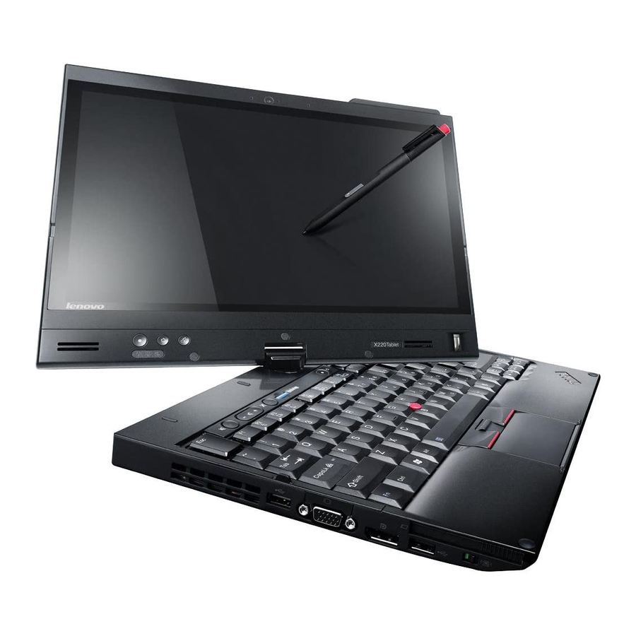
Lenovo ThinkPad X220 Tablet Hardware Maintenance Manual
Hardware maintenance manual
Hide thumbs
Also See for ThinkPad X220 Tablet:
- (294 pages) ,
- Manual d'utilisation (290 pages) ,
- Handboek voor de gebruiker (288 pages)
Table of Contents
Advertisement
Quick Links
Advertisement
Chapters
Table of Contents

Related Manuals for Lenovo ThinkPad X220 Tablet


Summary of Contents for Lenovo ThinkPad X220 Tablet
- Page 1 Hardware Maintenance Manual ThinkPad X220 Tablet and X220i Tablet...
- Page 2 “Notices” on page 140. Fifth Edition (March 2012) © Copyright Lenovo 2012. LIMITED AND RESTRICTED RIGHTS NOTICE: If data or software is delivered pursuant a General Services Administration “GSA” contract, use, reproduction, or disclosure is subject to restrictions set forth in Contract...
-
Page 3: Table Of Contents
FRU ....61 System supporting the Lenovo diagnostics Before servicing ThinkPad X220 Tablet and X220i programs .... - Page 4 ... Top view (ThinkPad X220 UltraBase) ..Notices ....
-
Page 5: About This Manual
® This manual contains service and reference information for the following ThinkPad products. ThinkPad X220 Tablet and Machine types (MT) 4294, 4296, 4297, 4298, 4299, 4300, and 4301 X220i Tablet Use this manual along with the advanced diagnostic tests to troubleshoot problems. - Page 6 Hardware Maintenance Manual...
-
Page 7: Chapter 1. Safety Information
• Reinstall all covers correctly before returning the machine to the customer. • Fan louvers on the machine help to prevent overheating of internal components. Do not obstruct fan louvers or cover them with labels or stickers. © Copyright Lenovo 2012... -
Page 8: Electrical Safety
Electrical safety Observe the following rules when working on electrical equipment. Important: Use only approved tools and test equipment. Some hand tools have handles covered with a soft material that does not insulate you when working with live electrical currents. Many customers have, near their equipment, rubber floor mats that contain small conductive fibers to decrease electrostatic discharges. -
Page 9: Safety Inspection Guide
– Use caution; do not become a victim yourself. – Switch off power. – Send another person to get medical aid. Safety inspection guide The purpose of this inspection guide is to assist you in identifying potentially unsafe conditions. As each machine was designed and built, required safety items were installed to protect users and service technicians from injury. -
Page 10: Grounding Requirements
Notes: 1. Use product-specific ESD procedures when they exceed the requirements noted here. 2. Make sure that the ESD protective devices you use have been certified (ISO 9000) as fully effective. When handling ESD-sensitive parts: • Keep the parts in protective packages until they are inserted into the product. •... - Page 11 DANGER Some standby batteries contain a small amount of nickel and cadmium. Do not disassemble a standby battery, recharge it, throw it into fire or water, or short-circuit it. Dispose of the battery as required by local ordinances or regulations. Use only the battery in the appropriate parts listing. Use of an incorrect battery can result in ignition or explosion of the battery.
- Page 12 DANGER Unless hot swap is allowed for the FRU being replaced, do as follows before removing it: power off the computer, unplug all power cords from electrical outlets, remove the battery pack, and disconnect any interconnecting cables. Hardware Maintenance Manual...
- Page 13 PERIGO Antes de ligar o computador após a substituição da FRU, certifique-se de que todos os parafusos, molas e outras peças pequenas estejam no lugar e não estejam soltos dentro do computador. Verifique isso sacudindo o computador e procurando ouvir sons de peças soltas. Peças metálicas ou lascas de metal podem causar curto-circuito.
- Page 14 A bateria de lítio pode causar incêndio, explosão ou graves queimaduras. Não a recarregue, remova seu conector polarizado, desmonte-a, aqueça-a acima de 100°C (212°F), incinere-a, ou exponha o conteúdo de sua célula à água. Descarte a bateria conforme requerido pelas leis ou regulamentos locais. Use somente a bateria nas partes listadas apropriadas.
- Page 15 Certaines batteries de secours contiennent du nickel et du cadmium. Ne les démontez pas, ne les rechargez pas, ne les exposez ni au feu ni à l'eau. Ne les mettez pas en court-circuit. Pour les mettre au rebut, conformez-vous à la réglementation en vigueur. Lorsque vous remplacez la pile de sauvegarde ou celle de l'horloge temps réel, veillez à...
- Page 16 DANGER Si le remplacement à chaud n'est pas autorisé pour l'unité remplaçable sur site que vous remplacez, procédez comme suit avant de retirer l'unité : mettez l'ordinateur hors tension, débranchez tous les cordons d'alimentation des prises de courant, retirez le bloc de batterie et déconnectez tous les câbles d'interconnexion.
- Page 17 Die Leuchtstoffröhre im LCD-Bildschirm enthält Quecksilber. Bei der Entsorgung die örtlichen Bestimmungen für Sondermüll beachten. Der LCD-Bildschirm besteht aus Glas und kann zerbrechen, wenn er unsachgemäß behandelt wird oder der Computer auf den Boden fällt. Wenn der Bildschirm beschädigt ist und die darin befindliche Flüssigkeit in Kontakt mit Haut und Augen gerät, sollten die betroffenen Stellen mindestens 15 Minuten mit Wasser abgespült und bei Beschwerden anschließend ein Arzt aufgesucht werden.
- Page 18 Hardware Maintenance Manual...
- Page 19 Chapter 1 Safety information...
- Page 20 Antes de encender el sistema despues de sustituir una FRU, compruebe que todos los tornillos, muelles y demás piezas pequeñas se encuentran en su sitio y no se encuentran sueltas dentro del sistema. Compruébelo agitando el sistema y escuchando los posibles ruidos que provocarían. Las piezas metálicas pueden causar cortocircuitos eléctricos.
- Page 21 Las baterías contienen pequeñas cantidades de níquel. No las desmonte, ni recargue, ni las eche al fuego o al agua ni las cortocircuite. Deséchelas tal como dispone la normativa local. Utilice sólo baterías que se encuentren en la lista de piezas al sustituir la batería. La utilización de una batería no apropiada puede provocar la ignición o explosión de la misma.
-
Page 22: Laser Compliance Statement (Multilingual Translations)
Laser compliance statement (multilingual translations) The laser compliance statements in this section are provided in the following languages: • English • Arabic • Brazilian Portuguese • French • German • Hebrew • Japanese • Korean • Spanish • Traditional Chinese Hardware Maintenance Manual... - Page 23 Chapter 1 Safety information...
- Page 24 Hardware Maintenance Manual...
- Page 25 Chapter 1 Safety information...
- Page 26 Hardware Maintenance Manual...
- Page 27 Chapter 1 Safety information...
- Page 28 Hardware Maintenance Manual...
-
Page 29: Chapter 2. Important Service Information
– “FRU identification for CTO, CMV, and GAV products” on page 25 Important: Advise customers to contact the Lenovo Customer Support Center if they need any assistance in obtaining or installing any software fixes, drivers, and UEFI BIOS downloads. Telephone numbers for Lenovo Support are available at: http://www.lenovo.com/support/phone... -
Page 30: Strategy For Replacing A Hard Disk Drive
1, and assigned drive D:. The mSATA drive is installed in the wireless WAN card slot of the computer. The Lenovo preloaded software is installed on the mSATA drive. Always try to run a low-level format before replacing a hard disk drive. This will cause all customer data on the hard disk to be lost. -
Page 31: Strategy For Replacing Frus For Cto, Cmv, And Gav
Dynamic Configure To Order (CTO) This provides the ability for a customer to configure a Lenovo solution from an eSite, and have this configuration sent to fulfillment, where it is built and shipped directly to the customer. The machine label, Product Entitlement Warehouse (PEW), eSupport, and the HMM will load these products as the 4-digit MT and 3-digit model, where model = “CTO”... - Page 32 • eSupport can be used to view the list of key commodities built in a particular machine serial (this is the same record found in PEW). • eSupport can be accessed at the following Web site: http://www.lenovo.com/support • To view the key commodities, do the following: 1. Click Products & Service Warranty.
-
Page 33: Chapter 3. General Checkout
“What to do first” on page 27 • “Checkout guide” on page 28 – “System supporting the Lenovo ThinkVantage Toolbox program and the PC-Doctor for DOS diagnostics program” on page 28 – “System supporting the Lenovo diagnostics programs” on page 33 •... -
Page 34: Checkout Guide
System supporting the Lenovo ThinkVantage Toolbox program and the PC-Doctor for DOS diagnostics program The section provides information about ThinkPad computers that support the Lenovo ThinkVantage Toolbox ® program and the PC-Doctor for DOS diagnostics program. Some descriptions might not apply to your particular computer. - Page 35 Configuration utility for DOS. The utility is available on the following Web site: http://www.lenovo.com/support PC-Doctor cannot be used to test a device that is in the docking station, even if the computer supports the docking station.
- Page 36 The options on the test menu are as follows: Diagnostics Interactive Tests • Run Normal Test • Keyboard • Run Quick Test • Video • CPU/Coprocessor • Internal Speaker • System Memory • Mouse • Systemboard • Diskette • Video Adapter •...
-
Page 37: Lenovo Thinkvantage Toolbox
While the Windows operating system is running, press the ThinkVantage button. To start this program, do the following: • Click Start ➙ Control Panel ➙ System and Security ➙ Lenovo - System Health and Diagnostics. Windows Vista and Windows XP: Click Start ➙... -
Page 38: Fru Tests
Select one of the categories listed below to display symptoms and solutions: • Check System Health • System and Device Tests • Lenovo Troubleshooting Center • System Reports • Updates and Support PC-Doctor for Rescue and Recovery In some models of ThinkPad Notebook, the Rescue and Recovery workspace enables you to run the PC-Doctor program to test the hardware features of the computer. -
Page 39: System Supporting The Lenovo Diagnostics Programs
It also can be downloaded from http://www.lenovo.com/diags. To run the Lenovo Solution Center program, click Start ➙ Control Panel ➙ System and Security ➙ Lenovo - System Health and Diagnostics, and then follow the instructions on the screen. -
Page 40: Uefi Diagnostic Program
F12 key. 3. Press the Tab key to switch to the Application Menu window. 4. Use the arrow keys to select Lenovo Diagnostics and then press Enter. The main screen of the UEFI diagnostic program is displayed. -
Page 41: Power System Checkout
2. Click Lenovo Bootable Diagnostics. 3. Follow the instructions on the Web site to create a bootable diagnostic medium on a USB device or CD. To use the diagnostic medium you have created, do one of the following: • If you have created the bootable diagnostic medium on a USB device, do the following: 1. -
Page 42: Checking Operational Charging
• If the power-on indicator does not turn on, check the power cord of the ac power adapter for correct continuity and installation. • If the computer does not charge during operation, go to “Checking operational charging” on page 36. To check the ac power adapter, do the following: 1. -
Page 43: Checking The Backup Battery
2. Remove the battery pack and measure the voltage between battery terminals 1 (+) and 7 (-). See the following figure: Terminal Voltage (V dc) + 0 to + 16.8 Ground (-) 7(-) 6(-) 2(+) 1(+) 3. If the voltage is less than +11.0 V dc, the battery pack has been discharged. Note: Recharging will take at least 3 hours, even if the indicator does not turn on. - Page 44 Hardware Maintenance Manual...
-
Page 45: Chapter 4. Related Service Information
Service Web site: When the latest maintenance diskette and the system program service diskette become available, they will be posted on http://www.lenovo.com/support. Restoring the factory contents by using Product Recovery discs When the hard disk drive (HDD) or solid state drive (SSD) is replaced because of a failure, no Product Recovery program is on the new drive. - Page 46 Recovery Disc Set and the drive at the same time so that you can recover the new drive with the pre-installed software when they arrive. For information on which discs to order, see “Recovery discs” on page 134. The recovery disc set consists of the user instructions and the following set of DVDs to restore the computer to the original factory configuration.
-
Page 47: Passwords
Attention: If the user HDP has been forgotten, check whether a master HDP has been set. If it has, it can be used for access to the hard disk drive. If no master HDP is available, neither Lenovo nor Lenovo authorized service technicians provide any services to reset either the user or the master HDP, or to recover data from the hard disk drive. -
Page 48: How To Remove The Hard-Disk Password
Attention: If User only mode is selected and the user HDP has been forgotten and cannot be made available to the service technician, neither Lenovo nor Lenovo authorized service technicians provide any services to reset the user HDPs or to recover data from the hard disk drive. The hard disk drive can be replaced for a scheduled fee. -
Page 49: Sleep (Standby) Mode
1. Press Fn+F3. A panel for selecting a power plan (in Windows XP, power scheme) appears. 2. Select Power off display (keep current power plan) (in Windows XP, keep current power scheme). You can also put the computer into screen blank mode, press ThinkVantage button and use the ThinkVantage Productivity Center. -
Page 50: Symptom-To-Fru Index
• If you have defined one of the following actions as the event that causes the system to go into hibernation mode, perform that action. – Closing the lid. – Pressing the power button. – Pressing Fn+F4 keys. Also, the computer goes into hibernation mode automatically in either of the following conditions: •... -
Page 51: Numeric Error Codes
Numeric error codes Table 2. Numeric error codes Symptom or error FRU or action, in sequence 0175 System board. Bad CRC1, stop POST task - The EEPROM checksum is not correct. 0176 1. Run the ThinkPad Setup program, and save the System Security - The system has been tampered with. - Page 52 Table 2. Numeric error codes (continued) FRU or action, in sequence Symptom or error 0197 The remote configuration for the security chip has Invalid remote change requested. failed. Confirm the operation and try again. 0199 1. Run the ThinkPad Setup program, and then save System Security - Security password retry count the current setting by pressing F10.
- Page 53 Table 2. Numeric error codes (continued) FRU or action, in sequence Symptom or error 0270 1. Charge the backup battery for more than 8 hours Real-time clock error. by connecting the ac power adapter. 2. Replace the backup battery and run the ThinkPad Setup program to reset the time and date.
- Page 54 ESC. If in the primary drive bay the customer is using a supported Lenovo HDD with an old firmware, the customer needs to update its firmware to the latest. The latest version is available at http://www.lenovo.com/support...
-
Page 55: Error Messages
Table 2. Numeric error codes (continued) FRU or action, in sequence Symptom or error 2102 1. Reseat the hard disk drive. Initialization error on HDD1 (Ultrabay hard disk drive) 2. Ultrabay hard disk drive. 3. System board. 2110 1. Reseat the hard disk drive. Read error on HDD0 (Main hard disk drive) 2. -
Page 56: Beep Symptoms
Table 3. Error messages (continued) FRU or action, in sequence Symptom or error 1. Check that the operating system has no failure and is installed correctly. 2. Reinstall the operation system. Excluded from boot order. • Enter the ThinkPad Setup program and add the device in boot order. -
Page 57: Lcd-Related Symptoms
If the LCD you are servicing has two or less visible defective pixels, it should not be considered faulty. However, if the LCD has three or more visible defective pixels, it will be deemed as defective by Lenovo and it should be replaced. - Page 58 3. Remove or disconnect all of the following devices: a. Non-ThinkPad devices b. Devices attached to the docking station or the port replicator c. Printer, mouse, and other external devices d. Battery pack e. Hard disk drive f. External diskette drive or optical drive g.
-
Page 59: Copyright Lenovo
Chapter 5. Status indicators This chapter presents the system status indicators that show the status of the computer. © Copyright Lenovo 2012... - Page 60 Table 7. Status indicators Indicator Meaning Wireless LAN status The wireless LAN feature is on, and the radio link is ready for use, Green: or the data is being transmitted. Blinking Data is being transmitted (for some models). green: Wireless status Green: Wireless PAN (Bluetooth wireless or Wireless USB) is operational.
-
Page 61: Chapter 6. Fn Key Combinations
Fn+F7 combination is available for switching a display output location. For Windows 7: Switch a display output location • Computer display only (LCD) • Computer display and external monitor (same image) • Computer display and external monitor (extended desktop) • External monitor only © Copyright Lenovo 2012... - Page 62 Table 8. Fn key combinations (continued) Key combination Description Note: To switch between the computer display and an external monitor, the Win+P key combination is also available. For Windows Vista and Windows XP: Switch a display output location • External monitor •...
-
Page 63: Chapter 7. Fru Replacement Notices
CRU; and (2) you may be charged for the replacement CRU if Lenovo does not receive the defective part within thirty (30) days of your receipt of the replacement CRU. See your Lenovo Limited Warranty documentation for full details. -
Page 64: Retaining Serial Numbers
If you replace the system board, you must restore the serial number of the system unit to its original value. Before replacing the system board, save the original serial number by doing the following: 1. Install the LENOVO ThinkPad Hardware Maintenance Diskette Version 1.76 or later, and restart the computer. -
Page 65: Retaining The Uuid
When you replace the system board, you must set the UUID on the new system board as follows: 1. Install the LENOVO ThinkPad Hardware Maintenance Diskette Version 1.76 or later, and restart the computer. 2. From the main menu, select 4. Assign UUID. A new UUID is created and written. If a valid UUID already exists, it is not overwritten. - Page 66 Hardware Maintenance Manual...
-
Page 67: Chapter 8. Removing And Replacing A Fru
CRU; and (2) you may be charged for the replacement CRU if Lenovo does not receive the defective part within thirty (30) days of your receipt of the replacement CRU. See your Lenovo Limited Warranty documentation for full details. -
Page 68: Before Servicing Thinkpad X220 Tablet And X220I Tablet Models
Before servicing ThinkPad X220 Tablet and X220i Tablet models Removing the SIM card: Some models of the ThinkPad X220 Tablet and X220i Tablet you are servicing might have the SIM card that the customer has been installed. If the computer you are servicing has the SIM card, remove it before you start the servicing. -
Page 69: 1010 Digitizer Pen
The only exception to this is if the battery pack is physically damaged or a customer is reporting a possible safety issue. If Lenovo ThinkVantage Toolbox is not installed in the computer, the customer should download this program before a non-physically damaged battery pack is replaced. Note that the replacement of a physically damaged battery pack is not covered by the warranty. -
Page 70: 1030 Hard Disk Drive (Hdd) And Solid State Drive (Ssd)
When installing: Install the battery pack along the slide rails of the slot. Make sure that the left battery release lever is in the locked position. 1030 Hard disk drive (HDD) and solid state drive (SSD) • “1020 Battery pack” on page 63 Attention: •... - Page 71 Step Screw (quantity) Color Torque Black 0.181 Nm Hard disk drive screw, M3 × 3 mm, wafer-head, nylon-coated (1) (1.85 kgfcm) Chapter 8 Removing and replacing a FRU...
-
Page 72: 1040 Dimm
HDD and HDD rubber rails: SSD and SSD spacers: When installing: Rubber rails on the hard disk drive or spacers on the solid state drive must be attached to the replacement drive. Otherwise the drive cannot be installed properly. 1040 DIMM For access, remove this FRU: •... - Page 73 Removal steps of DIMM Remove the DIMM slot cover as shown in the following figure. Note: Loosen the screws Note: If only one DIMM is used on the computer you are servicing, the card must be installed in SLOT-0 , but not in SLOT-1 When installing: Chapter 8 Removing and replacing a FRU...
-
Page 74: 1050 Hinge Caps
Insert the notched end of the DIMM into the socket. Press the DIMM firmly, and pivot it until it snaps into place. Make sure that it is firmly installed in the slot and does not move easily. 1050 Hinge caps For access, remove this FRU: •... - Page 75 Removal steps of keyboard Remove the screws Step Icon Screw (quantity) Color Torque M2 × 6 mm, wafer-head, nylon-coated (2) Black 0.181 Nm (1.85 kgfcm) Slightly press the keyboard and slide it a little bit forward, in the direction shown by arrow , to detach the front edge of the keyboard from the frame.
- Page 76 When installing: 1. Attach the keyboard connector firmly. 2. Make sure that the keyboard edge is under the frame as shown in the following figure. Then press the keys to latch the keyboard firmly in place. 3. Gently press the keys with your palms and slightly slide the keyboard toward you until it snaps into position.
-
Page 77: 1070 Palm Rest
4. Secure the keyboard by tightening the screws from the bottom side of the computer. 1070 Palm rest For access, remove these FRUs in order: • “1020 Battery pack” on page 63 • “1060 Keyboard” on page 68 Removal steps of palm rest Step Icon Screw (quantity) - Page 78 When installing: When you attach the palm rest, do as follows: 1. Attach the touch pad connector firmly to the system board. 2. Press the left and right top edges of the palm rest to fit it into place. 3. Push the front side of the palm rest until it clicks into place. 4.
-
Page 79: 1080 Backup Battery
1080 Backup battery DANGER Use only the battery specified in the parts list for your computer. Any other battery could ignite or explode. For access, remove these FRUs in order: • “1020 Battery pack” on page 63 • “1060 Keyboard” on page 68 •... - Page 80 Removal steps of backup battery Hardware Maintenance Manual...
-
Page 81: 1090 Pci Express Mini Card For Wireless Lan/Wimax
When installing: Make sure that the battery connector is attached firmly. 1090 PCI Express Mini Card for wireless LAN/WiMAX For access, remove these FRUs in order: • “1020 Battery pack” on page 63 • “1060 Keyboard” on page 68 • “1070 Palm rest”... -
Page 82: Step
Step Screw (quantity) Color Torque M2 × 3.5 mm, wafer-head, nylon-coated (1) Silver 0.181 Nm (1.85 kgfcm) When installing • In models with a wireless LAN card that has two antenna connectors, plug the gray cable into the jack labeled MAIN or M on the card, and the black cable into the jack labeled AUX or A. If the computer you are servicing has three cables, put the white cable in the cable protection tube. -
Page 83: 1100 Pci Express Mini Card For Wireless Wan
• In models with a wireless LAN card that has three antenna connectors, plug the gray cable (MAIN) into the jack labeled TR1, the white cable (third) into the jack labeled RO or TR3, and the black cable (AUX) into the jack labeled TR2 on the card. 1100 PCI Express Mini Card for wireless WAN For access, remove these FRUs in order: •... -
Page 84: 1110 Bluetooth Daughter Card
When installing: When you install the card, plug the red cable into the jack labeled MAIN on the card, and the blue cable into the jack labeled AUX. If the computer you are servicing is the wireless WAN-ready model, put the antenna cables in the cable protection tube and place them as shown in the following figure. -
Page 85: 1120 Keyboard Bezel
Removal steps of Bluetooth daughter card Step Screw (quantity) Color Torque 0.181 Nm M2 × 3.5 mm, wafer-head, nylon-coated (1) Silver (1.85 kgfcm) When installing: Make sure that the connector is attached firmly. 1120 Keyboard bezel For access, remove these FRUs in order: •... -
Page 86: M2 × 6 Mm, Wafer-Head, Nylon-Coated
Removal steps of keyboard bezel Step Screw (quantity) Color Torque M2 × 6 mm, wafer-head, nylon-coated (3) Black 0.181 Nm (1.85 kgfcm) 0.181 Nm M2 × 3.5 mm, wafer-head, nylon-coated (2) Silver (1.85 kgfcm) Torque Step Screw (quantity) Color M2 × 2 mm, wafer-head, nylon-coated (4) Black 0.181 Nm (1.85 kgfcm) -
Page 87: 1130 Lcd Assembly
In step , detach the claws. Then remove the keyboard bezel in the direction shown by arrow Attention: When you service the keyboard bezel, avoid any kind of rough handling. When installing: Make sure that all the claws are attached firmly. 1130 LCD assembly For access, remove these FRUs in order: •... - Page 88 • “1100 PCI Express Mini Card for wireless WAN” on page 77 • “1120 Keyboard bezel” on page 79 Removal steps of LCD assembly Step Screw (quantity) Color Torque M2.5 × 6 mm, wafer-head, nylon-coated (2) Black 0.392 Nm (4 kgfcm) Torque Step Screw (quantity)
- Page 89 When installing: • Make sure that you attach the connectors firmly. Chapter 8 Removing and replacing a FRU...
-
Page 90: 1140 Dc-In Connector, Base Cover, Fan, Digitizer Pen Case, And Pen Switch Assembly
• Make sure that you route the cables correctly and you tape up the cables in the proper positions as shown in the following figure. • When you route the cables, make sure that they are not subjected to any tension. Tension could cause the cables to be damaged by the cable guides, or a wire to be broken. -
Page 91: Color Torque
Step Screw (quantity) Color Torque M1.6 x 3 + 4.2A mm, shoulder socket-head, nylon-coated (1) Black 0.181 Nm (1.85 kgfcm) M2 x 3.5 mm, wafer-head, nylon-coated (1) Silver 0.181 Nm (1.85 kgfcm) Chapter 8 Removing and replacing a FRU... - Page 92 Step Screw (quantity) Color Torque 0.181 Nm M2 × 3.5 mm, wafer-head, nylon-coated (4) Silver (1.85 kgfcm) When installing: Make sure that the wireless switch is adjusted as shown by callout Turn the system board over, and then disconnect the DC-in connector, the fan connector, and the pen switch connector from the system board.
-
Page 93: When Installing
Disconnect the fan assembly from the system board. Torque Step Screw (quantity) Color M2 × 3.5 mm, flat-head, nylon-coated (1) Silver 0.181 Nm (1.85 kgfcm) When installing: • Before you attach the fan assembly to the computer, apply thermal grease, at an amount of 0.2 grams, on the part marked as in the following figure. - Page 94 Applying labels to the base cover: The new base cover FRU is shipped with a kit containing labels of several kinds. Note: If the Windows Authentication label (COA) is attached to a part that is replaced, return the old part with the label attached to the customer, or provide a letter to the customer stating what the label was originally on the system and what the label part number, serial number, and product key were.
-
Page 95: 1150 System Board And Expresscard Slot Assemblies
Israel label (67.8 mm x 27.9 mm) Israel label (72.2 mm x 29.7 mm) Israel label (76.2 mm x 31.8 mm) Ethernet label or Onboard LAN MAV address label For some models, you need to apply two FCC labels, . Check the old base cover; if it has two FCC labels, apply both to the new base cover. - Page 96 If the system supports PC-Doctor for DOS, after replacing the system board, run PC-Doctor for DOS to make sure that HDD Active Protection System still functions. The procedure is as follows: 1. Place the computer on a horizontal surface. 2. Run Diagnostics ➙ ThinkPad Devices ➙ HDD Active Protection Test. Attention: Do not apply physical shock to the computer while the test is running.
-
Page 97: 1160 Speaker Assembly
Torque Step Screw (quantity) Color M2 × 3.5 mm, wafer-head, nylon-coated (2) Silver 0.181 Nm (1.85 kgfcm) Turn the system board over, and then remove the ExpressCard slot assembly from the system board. 1160 Speaker assembly For access, remove these FRUs in order: •... -
Page 98: 1170 Msata Solid State Drive
Removal steps of speaker assembly Remove the speaker assembly from the base cover assembly. Torque Step Screw (quantity) Color M2 × 3mm, wafer-head, nylon-coated (1) Black 0.181 Nm (1.85 kgfcm) When installing: Route the speaker cables along the cable guides as shown in the following figure. 1170 mSATA solid state drive For access, remove these FRUs in order: •... -
Page 99: 2010 Lcd Front Bezel
Removal steps of mSATA solid state drive Step Screw (quantity) Color Torque M2 × 3 mm, flat-head, nylon-coated (1) Black 0.181 Nm (1.85 kgfcm) 2010 LCD front bezel For access, remove this FRU: • “1020 Battery pack” on page 63 Chapter 8 Removing and replacing a FRU... - Page 100 Removal steps of LCD front bezel Step Screw cap Screw (quantity) Color Torque Black 0.392 Nm M2.5 × 8 mm, wafer-head, nylon-coated (3) (4 kgfcm) When installing: Attach the fingerprint reader connector firmly. Hardware Maintenance Manual...
-
Page 101: 2020 Micro-Processor Card
2020 Micro-Processor card For access, remove these FRUs in order: • “1020 Battery pack” on page 63 • “2010 LCD front bezel” on page 93 Removal steps of Micro-Processor card Step Screw (quantity) Color Torque M2 × 3.5 mm, wafer-head, nylon-coated (2) Silver 0.181 Nm (1.85 kgfcm) -
Page 102: 2030 Hinge
When installing: Make sure that connectors are attached firmly. 2030 Hinge For access, remove these FRUs in order: • “1010 Digitizer pen” on page 63 • “1020 Battery pack” on page 63 • “1050 Hinge caps” on page 68 • “1060 Keyboard”... -
Page 103: 2040 Lcd Panel And Lcd Cable
Removal steps of the hinge Step Screw (quantity) Color Torque M2.5 × 6 mm, wafer-head, nylon-coated (2) Black 0.392 Nm (4 kgfcm) Detach the hinge from the LCD rear cover, and gently pull the cables out through the guide hole in the hinge. Pull them all at once. - Page 104 • “2030 Hinge” on page 96 Removal steps of LCD panel and LCD cable Torque Step Screw cap Screw (quantity) Color M2.5 × 8 mm, wafer-head, nylon-coated (6) Black 0.392 Nm (4 kgfcm) — 0.181 Nm M2 × 3.5 mm, wafer-head, nylon-coated (3) Silver (1.85 kgfcm) In step...
- Page 105 When installing: • Make sure that all the claws are attached firmly. • When attaching the LCD panel to the cover, gently press the left and right edges covered with metal. Do not press the surface of the panel or apply any excessive force to the panel. Turn the LCD panel over, and then remove the LCD cable from the LCD panel.
-
Page 106: 2050 Integrated Camera
When installing: • Route the cable through the hooks and make sure the white dot on the cable is aligned with the hooks. Then paste a film on top of the hooks to secure the cable. • Keep the cable between callout short to prevent the cable from being winded. -
Page 107: 2060 Lcd Rear Cover And Wireless Antenna Cables
Removal steps of Integrated camera Step Screw (quantity) Color Torque 0.181 Nm M2 × 3.5 mm, wafer-head, nylon-coated (1) Silver (1.85 kgfcm) 2060 LCD rear cover and wireless antenna cables For access, remove these FRUs in order: • “1010 Digitizer pen” on page 63 •... - Page 108 Removal steps of LCD rear cover and wireless antenna cables Step Screw (quantity) Color Torque M2 × 3.5 mm, wafer-head, nylon-coated (1) Silver 0.181 Nm (1.85 kgfcm) In step , release the antenna cables from the cable guides of the rear cover. Hardware Maintenance Manual...
- Page 109 When installing: Place the antenna assembly as shown in the following figure. Wireless WAN antenna, AUX (blue) Wireless LAN antenna, AUX (black) Wireless LAN antenna, MAIN (gray) Wireless WAN antenna, MAIN (red) Attention: As you route the antenna cables, make sure that they are not subjected to any tension. Tension could cause the cables to be damaged by the cable guides, or a wire to be broken.
- Page 110 Hardware Maintenance Manual...
-
Page 111: Chapter 9. Locations
Chapter 9. Locations This chapter presents the locations of ThinkPad X220 Tablet and X220i Tablet features and hardware components. Front view Integrated camera Built-in microphone Security keyhole Tablet digitizer pen Hard disk drive (HDD) or solid state drive (SSD) Combo audio jack... -
Page 112: Rear View
Rear view Status indicators Note: For the description of each indicator, see Chapter 5 “Status indicators” on page 53. ExpressCard slot Wireless radio switch USB connector DisplayPort connector External monitor connector USB connector ac power connector Hardware Maintenance Manual... -
Page 113: Rear View (Tablet Mode)
Rear view (tablet mode) Tablet buttons Fingerprint reader Status indicators Note: For the description of each indicator, see Chapter 5 “Status indicators” on page 53. Bottom view Battery pack latch Battery pack Docking connector DIMM slots Built-in speakers Chapter 9 Locations... -
Page 114: Top View (Thinkpad X220 Ultrabase)
Top view (ThinkPad X220 UltraBase) Docking connector ac power connector Ethernet connector DisplayPort connector External monitor connector Headphone jack Microphone jack USB connectors Security keyhole Security lock key Serial Ultrabay Slim device Bottom view (ThinkPad X220 UltraBase) UltraBase eject request button... -
Page 115: Chapter 10. Parts List
CRU, Lenovo will ship the CRU to you. CRU information and replacement instructions are shipped with your product and are available from Lenovo at any time upon request. You may find a list of CRUs in the publications that ship with your product or at http://www.lenovo.com/CRUs. You may be required to return the defective part that is replaced by the CRU. -
Page 116: Overall
• FRUs marked with are available as options. Overall Hardware Maintenance Manual... - Page 117 Table 9. Parts list - Overall FRU no. LCD unit (see “LCD FRUs” on page 126.) Digitizer pen case assembly 04W1477 N Backup battery 02K7078 55Y3715 1-GB DDR3-1333 SDRAM SO-DIMM (PC3-10600) card • 4294-CTO • 4296-CTO, 2Rx • 4297-CTO • 4298-CTO, 38x, 3Mx, 3Nx •...
- Page 118 Table 9. Parts list - Overall (continued) FRU no. 04W2131 N System board assembly with Intel Core i5-2520M processor, AMT, non-TPM, non-AES • 4294-CTO • 4296-CTO • 4297-CTO • 4298-CTO, 4Ax, 49x • 4299-CTO • 4300-CTO • 4301-CTO System board assembly with Intel Core i5-2520M processor, non-AMT, TPM, AES 04W2129 N •...
- Page 119 Table 9. Parts list - Overall (continued) FRU no. 04W2134 N System board assembly with Intel Core i7-2620M processor, non-AMT, non-TPM, non-AES • 4294-CTO • 4296-CTO • 4297-CTO • 4298-CTO • 4299-CTO • 4300-CTO • 4301-CTO System board assembly with Intel Core i3-2310M processor, non-AMT, TPM, non-AES 04W2136 N •...
- Page 120 Table 9. Parts list - Overall (continued) FRU no. 04W1537 N System board assembly with Intel Core i5-2520M, non-AMT, non-TPM, non-AES • 4294-CTO, 29x, 28x • 4296-CTO, 3Ax, 28x • 4297-CTO • 4298-CTO • 4299-CTO • 4300-CTO • 4301-CTO System board assembly with Intel Core i7-2620M, AMT, TPM, AES 04W1538 N •...
- Page 121 Table 9. Parts list - Overall (continued) FRU no. 04W1543 N System board assembly with Intel Core i3-2310M, non-AMT, non-TPM, non-AES • 4294-CTO, 2Cx, 2Bx • 4296-CTO, 2Tx, 2Sx, 2Rx, 2Qx • 4297-CTO, 22x • 4298-CTO, 36x • 4299-CTO • 4300-CTO •...
- Page 122 Table 9. Parts list - Overall (continued) FRU no. 04W3281 N System board assembly with Intel Core i7-2620M, non-AMT, TPM, AES • 4294-CTO • 4296-CTO • 4297-CTO • 4298-CTO • 4299-CTO • 4300-CTO • 4301-CTO System board assembly with Intel Core i7-2620M, AMT, non-TPM, non-AES 04W3282 N •...
- Page 123 Table 9. Parts list - Overall (continued) FRU no. 04W3381 N System board assembly with Intel Core i7-2640M, AMT, non-TPM • 4294-CTO • 4296-CTO • 4297-CTO • 4298-CTO • 4299-CTO • 4300-CTO • 4301-CTO System board assembly with Intel Core i7-2640M, non-AMT, TPM 04W3382 N •...
- Page 124 Table 9. Parts list - Overall (continued) FRU no. 04W3599 N System board assembly with Intel Core i3-2370M, non-AMT, non-TPM • 4294-CTO • 4296-CTO • 4297-CTO • 4298-CTO • 4299-CTO • 4300-CTO • 4301-CTO Integrated Mobile Broadband (Gobi 3000 3G with GPS) 60Y3257 •...
- Page 125 Table 9. Parts list - Overall (continued) FRU no. 60Y3239 Integrated China Telecom Mobile Broadband (Huawei EM660) • 4294-CTO • 4296-CTO • 4297-CTO • 4298-CTO, 52x, 53x, 33x, 35x, 3Bx, 3Cx • 4299-CTO • 4300-CTO • 4301-CTO ThinkPad b/g/n Wireless (1x1 BGN) 60Y3247 •...
- Page 126 Table 9. Parts list - Overall (continued) FRU no. 60Y3233 Intel Centrino Ultimate-N 6300 • 4294-CTO • 4296-CTO • 4297-CTO • 4298-CTO, 4Ux • 4299-CTO, 2Gx, 2Lx, 2Rx, 3Cx, 54x • 4300-CTO • 4301-CTO Intel Centrino Advanced-N + WiMAX 6250 60Y3195 •...
- Page 127 Table 9. Parts list - Overall (continued) FRU no. Battery pack, 6 cell 42T4881 • 4294-CTO, 23x, 24x, 26x, 27x, 28x, 29x, 2Ax, 2Bx, 2Cx, 2Dx, 2Gx, 2Hx, 2Jx, 2Lx, 2Mx, 2Nx, 2Sx, 2Tx, 2Ux • 4296-CTO, 24x, 25x, 27x, 28x, 29x, 2Ax, 2Bx, 2Cx, 2Dx, 2Ex, 2Fx, 2Gx, 2Jx, 2Kx, 2Lx, 2Mx, 2Px, 2Ux, 2Xx, 2Yx, 2Zx, 32x, 33x, 34x, 35x, 36x, 37x, 38x, 39x, 3Bx, 3Cx, 3Dx, 3Ex, 3Fx, 3Gx, 3Hx, 3Jx, 3Lx, 3Mx, 3Nx, 3Rx, 3Sx, 3Tx, 3Ux, 3Vx, 3Wx, 3Xx, 3Yx •...
- Page 128 Table 9. Parts list - Overall (continued) FRU no. 42T1155 SATA hard disk drive, 320GB, 5,400 rpm • 4294-CTO, 2Kx, 2Px, 2Qx, 2Rx • 4296-CTO, 26x • 4297-CTO • 4298-CTO, 28x, 2Qx, 2Xx, 2Yx, 2Zx, 32x, 4Zx • 4299-CTO, 2Wx •...
- Page 129 Table 9. Parts list - Overall (continued) FRU no. 42T1159 SATA hard disk drive, 320 GB, 7,200 rpm • 4294-CTO, 2Bx, 2Ex, 2Gx, 2Jx, 2Nx, 2Sx, 2Tx, 2Ux • 4296-CTO, 23x, 2Ax, 2Bx, 2Cx, 2Ex, 2Fx, 2Hx, 2Kx, 2Lx, 2Nx, 2Qx, 2Tx, 2Ux, 2Wx, 2Xx, 2Yx, 2Zx, 32x, 33x, 34x, 36x, 37x, 39x, 3Ax, 3Bx, 3Dx, 3Fx, 3Gx, 3Hx, 3Jx, 3Kx, 3Lx, 3Mx, 3Nx, 3Px, 3Qx, 3Rx, 3Sx, 3Vx, 3Wx, 3Yx •...
- Page 130 4Sx, 4Vx, 4Wx, 56x • 4299-CTO, 2Cx, 2Dx, 2Gx, 2Jx, 2Kx, 4Tx, 4Ux, 4Vx, 55x • 4300-CTO • 4301-CTO Hard disk drive cover assembly 04W1414 * ThinkPad X220 UltraBase 04W1420 * ThinkPad X220 UltraBase 04W1890 * DVD-ROM drive 45N7485 • 4294-CTO •...
- Page 131 Table 9. Parts list - Overall (continued) FRU no. 45N7457 DVD/CD-RW combo drive • 4294-CTO, 23x, 24x, 2Hx, 2Lx, 2Mx • 4296-CTO, 27x, 28x, 2Ax, 2Jx, 2Lx, 2Nx, 33x, 35x, 3Bx, 3Hx, 3Ux, 3Vx • 4297-CTO, 22x • 4298-CTO, 2Ax, 2Sx, 33x, 34x, 35x, 36x, 3Nx, 3Sx, 3Tx, 44x, 4Jx, 4Kx •...
-
Page 132: Lcd Frus
Table 9. Parts list - Overall (continued) FRU no. • 4300-CTO • 4301-CTO Bluetooth daughter card 60Y3275 • 4294-CTO, 23x, 24x, 26x, 27x, 28x, 29x, 2Ax, 2Bx, 2Cx, 2Dx, 2Ex, 2Fx, 2Gx, 2Hx, 2Jx, 2Kx, 2Lx, 2Mx, 2Nx, 2Rx, 2Sx, 2Tx, 2Ux •... - Page 133 Table 10. Parts list - 12.5-in. HD LED backlight LCD for multi-touch panel LCD or outdoor LCD FRU no. LCD panel, 12.5-in. WXGA, LED backlight for multi-touch panel 04W1545 N • 4294-CTO, 23x, 24x, 29x, 2Fx, 2Gx, 2Hx, 2Jx, 2Kx, 2Lx, 2Mx, 2Nx, 2Px, 2Qx, 2Rx, 2Sx, 2Tx •...
- Page 134 Table 10. Parts list - 12.5-in. HD LED backlight LCD for multi-touch panel LCD or outdoor LCD (continued) FRU no. • 4298-CTO, 26x, 27x, 28x, 29x, 2Ax, 2Bx, 2Dx, 2Ex, 2Fx, 2Kx, 2Lx, 2Mx, 2Nx, 2Px, 2Sx, 2Ux, 2Wx, 2Xx, 2Yx, 34x, 35x, 37x, 3Ax, 3Bx, 3Fx, 3Mx, 3Nx, 3Px, 3Qx, 3Rx, 3Sx, 3Tx, 3Ux, 3Vx, 3Wx, 3Xx, 3Yx, 46x, 47x, 48x, 4Ax, 4Bx, 4Cx, 4Ex, 4Fx, 4Gx, 4Hx, 4Jx, 4Kx, 4Lx, 4Nx, 4Px, 4Tx, 4Ux, 4Vx, 4Wx, 4Xx, 4Zx, 53x, 54x, 56x •...
- Page 135 Table 10. Parts list - 12.5-in. HD LED backlight LCD for multi-touch panel LCD or outdoor LCD (continued) FRU no. Integrated camera 04W1364 N • 4294-CTO, 23x, 24x, 26x, 27x, 28x, 29x, 2Ax, 2Bx, 2Cx, 2Dx, 2Ex, 2Fx, 2Gx, 2Hx, 2Jx, 2Kx, 2Lx, 2Mx, 2Nx, 2Px, 2Qx, 2Rx, 2Sx, 2Tx, 2Ux •...
-
Page 136: Keyboard
Table 10. Parts list - 12.5-in. HD LED backlight LCD for multi-touch panel LCD or outdoor LCD (continued) FRU no. LED card 04W1777 N Speaker assembly 04W1782 N LCD button bezel with fingerprint reader 04W1550 N • 4294-CTO, 2Sx, 23x, 24x, 26x, 27x, 28x, 29x, 2Ax, 2Bx, 2Cx, 2Dx, 2Ex, 2Fx, 2Gx, 2Hx, 2Jx, 2Kx, 2Lx, 2Mx, 2Px, 2Qx, 2Sx, 2Tx, 2Ux •... -
Page 137: Miscellaneous Parts
Table 11. Parts list - Keyboard (continued) Language CRU ID German 45N2223 45N2083 45N2153 45N2224 45N2084 45N2154 Greek (U.S. English and Greek layout) Hungarian 45N2226 45N2086 45N2156 Icelandic 45N2227 45N2087 45N2157 Israel (Hebrew) 45N2225 45N2085 45N2155 Italian 45N2228 45N2088 45N2158 Japanese 45N2242 45N2102... -
Page 138: Ac Power Adapter
Table 12. Parts list - Miscellaneous parts (continued) • LCM LCD bezel screw mylar, (3) • LCM LCD bezel screw mylar, (3) • LCD side screw mylar, (8) • LCD side screw mylar, (8) • Microphone support mylar, (1) • Microphone support mylar, (1) •... -
Page 139: Power Cords
Power cords A ThinkPad power cord for a specific country or region is usually available only in that country or region: Table 14. Parts list - 2-pin power cords Country or region FRU no. Argentina 42T5020 42T5105 • Models: CTO, xxY Brazil 42T5180 42T5183... -
Page 140: Recovery Discs
Recovery discs Windows XP Professional DVDs Note: The Windows XP Professional recovery DVDs are available only for models with a valid Microsoft Windows XP Professional certificate of authenticity (COA) affixed to the system. Due to a Microsoft licensing limitation, if a model came with Windows XP Professional preinstalled from the factory, but has either a Windows 7 or Windows Vista COA affixed to the system, that model is eligible only for recovery DVDs that match the operating system specified on the COA. -
Page 141: Windows Vista Business (32 Bit) Dvds
Windows Vista Business (32 bit) DVDs Note: The Windows Vista recovery DVDs are available only for models with a valid Microsoft Windows Vista certificate of authenticity (COA) affixed to the system. Due to a Microsoft licensing limitation, if a model came with Windows Vista Business or Windows Vista Ultimate preinstalled from the factory, but has a Windows 7 COA affixed to the system, that model is eligible only for recovery DVDs that match the operating system specified on the COA. -
Page 142: Windows 7 Professional (64 Bit) Dvds
Table 20. Parts list - Windows 7 Professional (32 bit) recovery DVDs Language English 04T3571 Japanese 04T3569 Simplified Chinese 04T3566 French 04T3567 04T3568 German Spanish 04T3570 04T3572 English, Danish, Finnish, Swedish, and Norwegian English, Dutch, French, German, and Italian 04T3573 Windows 7 Professional (64 bit) DVDs Windows 7 Professional (64 bit) is preinstalled as the operating system in the following models: •... -
Page 143: Windows 7 Ultimate (32 Bit) Dvds
Table 21. Parts list - Windows 7 Professional (64 bit) recovery DVDs (continued) Language Japanese 04T3587 Korean /English 04T3588 Polish 04T3589 Romanian 04T3591 Portuguese 04T2237 Russian 04T3592 Serbian-Latin 04T3595 Simplified Chinese 04T3577 Slovakian 04T3593 Spanish 04T3594 Traditional Chinese 04T3578 Traditional Chinese (Hong Kong S.A.R.) 04T3585 Turkish 04T3596... -
Page 144: Windows 7 Home Basic (32 Bit) Dvds
Table 23. Parts list - Windows 7 Ultimate (64 bit) recovery DVDs Language English 04T3602 Windows 7 Home Basic (32 bit) DVDs • 4294-CTO • 4296-CTO • 4297-CTO • 4298-CTO • 4299-CTO • 4300-CTO • 4301-CTO Table 24. Parts list - Windows 7 Home Basic (32 bit) DVDs Language Arabic 04T3603... -
Page 145: Windows 7 Home Premium (64 Bit) Dvds
• 4296-CTO, 26x, 2Qx, 2Tx, 3Ax, 3Px • 4297-CTO • 4298-CTO • 4299-CTO • 4300-CTO • 4301-CTO Table 26. Parts list - Windows Home Premium (32 bit) recovery DVDs Language English 04T3617 Indian English 04T3616 Simplified Chinese 04T3615 Windows 7 Home Premium (64 bit) DVDs •... -
Page 146: Common Service Tools
Lenovo representative for information on the products and services currently available in your area. Any reference to a Lenovo product, program, or service is not intended to state or imply that only that Lenovo product, program, or service may be used. Any functionally equivalent product, program, or service that does not infringe any Lenovo intellectual property right may be used instead. -
Page 147: Electronic Emissions Notices
All information contained in this document was obtained in specific environments and is presented as an illustration. The result obtained in other operating environments may vary. Lenovo may use or distribute any of the information you supply in any way it believes appropriate without incurring any obligation to you. - Page 148 The following terms are trademarks of Microsoft Corporation in the United States, other countries, or both: Windows Windows Vista The following are trademarks of Intel Corporation or its subsidiaries in the United States, other countries, or both: Intel Intel Celeron Intel Core 2 Duo Intel Core 2 Solo Other company, product, or service names may be the trademarks or service marks of others.
- Page 150 Part Number: 0A60175_04 Printed in China (1P) P/N: 0A60175_04 *0A60175_04*...