Craftsman Professional 247.88830 Operator's Manual
30" snow thrower
Hide thumbs
Also See for Professional 247.88830:
- Operator's manual (72 pages) ,
- Operator's manual (13 pages)
Table of Contents
Advertisement
Available languages
Available languages
Operator's
Manual
P
R
0
F
E
S
S
I
0
N
A
30" SNOW THROWER
Model No. 247.88830
CAUTION:
Before
using
this product,
read this
manual
and follow
all
safety
rules
and operating
instructions.
o SAFETY
ASSEMBLY
OPERATION
MAINTENANCE
PARTS LIST
o ESPANOL
Sears, Roebuck and Co., Hoffman
Estates,
IL 60179, U.S.A.
Visit our website:
www.craftsman.com
FORMNO. 769-05137B
5/17/2010
Advertisement
Table of Contents

Related Manuals for Craftsman Professional 247.88830


Summary of Contents for Craftsman Professional 247.88830
- Page 1 SAFETY ASSEMBLY OPERATION MAINTENANCE PARTS LIST CAUTION: Before using o ESPANOL this product, read this manual and follow safety rules and operating instructions. Sears, Roebuck and Co., Hoffman Estates, IL 60179, U.S.A. Visit our website: www.craftsman.com FORMNO. 769-05137B 5/17/2010...
- Page 2 Service &Maintenance ....Pages 18-23 Service Numbers ....BackPage CRAFTSMAN PROFESSIONAL FULL WARRANTY Whenoperatedand maintained accordingto all suppliedinstructions, ifthis Craftsmansnowthrowerfails due to a defectin materialor workman- shipwithin two yearsfrom the dateof purchase,call 1-800-4-MY-HOME (1-800-469-4663) to arrangeforfree in-home repair(or replacement i f repairprovesimpossible).
- Page 3 This machinewas builtto be operatedaccordingto the safeopera- This symbolpointsout importantsafetyinstructionswhich,if not tion practicesin this manual.As with anytype of powerequipment, followed,couldendangerthepersonalsafetyand/orpropertyof carelessnessor error on the partof the operatorcan resultin serious yourselfand others. Readand followall instructionsin this manual injury.This machineis capableof amputatingfingers,hands,toes beforeattemptingto operatethis machine.Failureto complywith and feet and throwingdebris.Failureto observethe followingsafety these instructionsmay resultin personalinjury.Whenyou seethis...
- Page 4 Safe Handling of Gasoline • Exerciseextremecautionwhenoperatingon or crossinggravel surfaces.Stay alertfor hidden hazardsor traffic. Toavoidpersonalinjuryor propertydamageuseextremecare in handlinggasoline.Gasolineis extremelyflammableand the vaporsare • Exercisecautionwhenchangingdirectionand whileoperatingon explosive.Seriouspersonalinjurycan occurwhengasolineis spilled slopes. on yourselfor yourclotheswhichcan ignite.Washyour skin and • Planyoursnow-throwing patternto avoiddischargetowards changeclothesimmediately. windows,walls,cars etc. Thus,avoidingpossibleproperty •...
- Page 5 MAINTENANCE & STORAGE DO NOT MODIFY ENGINE • Nevertamperwith safetydevices.Checktheirproperoperation Toavoidseriousinjuryor death,do not modifyengine in any way. regularly.Referto the maintenance and adjustmentsectionsof Tampering with the governorsettingcanlead to a runawayengineand this manual. cause it to operateat unsafespeeds.Nevertamperwithfactory setting of engine governor. •...
- Page 6 SAFETY SYMBOLS This pagedepictsand describessafetysymbolsthat mayappear on this product. Read,understand,and followall instructionson the machine beforeattemptingto assembleand operate. READ THE OPERATOR'S MANUAL(S) Read, understand, and follow all instructions in the manual(s) before attempting to assemble operate WARNING-- ROTATING BLADES Keep hands out of inlet and discharge openings while machine is running.
- Page 7 1001 IIIO=NV]IO "lVflNV_ S,UOIVU3dOQV3H"_ "S33VdUnS 13MH9 NO 9NilVU3dO N3HM NOIIRVO V tdlX3 3SR"SU3ONVISIB lV 30UVHOSBO 13:IUIQ H:IA:IN 'S3iURrNi $13]F80 NMOUH1 QiOAV 01 "t_ 7]NiHOV_ 9Ni31Atd_S U O9Nigoo13NI'I :IUO:J3g Q3dd01S 3MH SIUVd9HJAOI_ 1 W lJlHn S31QNVH QNIH38 NiV_3UQNV '::lNiON::l dOlS'SH3A:rl H31R13 3_)VON:lSJ(] "_ ":11AH3 3OSVHOSJQ 90"13NI3 0 1 1001 lflO=NV:rl3 :lSfl"_ "l:GdQNV 8OHVH :11Vlrld_V HVO U39flV}JO _13l13dL_l HIIM...
- Page 8 NOTE:References to rightor left sideof the snowthrowerare determined from behindthe unit in the operatingposition(standing directlybehindthe snow thrower,facingthe handlepanel). Chute Control Head REMOVING FROM CARTON Cut the cornersof thecarton and lay the sidesflat on the ground. Chute Support Removeand discard all packinginserts. Movethe snowthrowerout of thecarton.
- Page 9 Placechuteontochute baseand ensurehexrod is positioned under handlepanel.Installhex boltpreviouslyremovedbut do TopView not securewith wingnut at this time.See Figure4. Squeezethetriggeron the handlepaneljoystickand rotatethe chute byhand to face forward.The holesin the chutecontrol inputwill be facing up. See Figure5. NOTE:The chutewill not rotatewithoutsqueezing the triggeron the joystick.
- Page 10 Makesureall cables are routedto the left of the chutecontrol rod. Line up the hole in the hexend of chute rod with the arrowon the /i _ input shaftand insertthe hex end of the rod intothe input shaft belowjoystickon handlepanel.See Figure7. NOTE:Thechute rod will fit snugglyintothe inputshaft.
- Page 11 10. Checkthat all cables are properlyroutedthroughthecable guide "_ on theengine.See Figure10. NOTE: if the chutecontrol is notassembledcorrectlyit will not move freelynor will it movefully to the rightand left. 11. Theextensioncord forthe electricstarteris fastenedwith a cabletie to the rearof the auger housingfor shippingpurposes. Cutthe cabletie and removecord beforeoperatingthe unit.
- Page 12 Chute Clean-Out Tool A chute clean-out tool is fastenedto the top of the augerhousing with a mountingclip. See Figure12.The tool is designedto cleara chuteassemblyof ice and snow.This item is fastenedwith a cabletie at the factory.Cut thecable tie beforeoperatingthe snowthrower. Chutedean-out Tool loft _1 .allmovingpartshave stoppedbeforeusingthe clean-outtool to clearthe chuteassembly.
- Page 13 Use a middleor lowerpositionwhenthearea to be clearedis uneven,such as a graveldriveway. NOTE:If you chooseto operatethe snowthroweron a gravelsurface, keepthe skid shoesin positionfor maximumclearancebetweenthe groundand the shaveplate. Operatinga snowthrowerequippedwith steelskid shoes may result in damageto naturalstonepaversurfaces(e.g.sandstone,blue- stone,limestone). Forinformationon availablepolymerskid shoes, call 1-800-4MY-HOME. Toadjustthe skid shoes: Loosenthe fourhex nuts (two on each side)and carriagebolts.
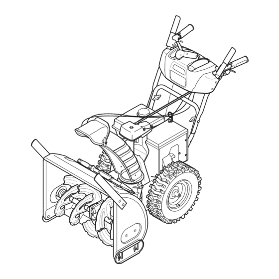
- Page 14 Drive Control Shift Lever / Four=Way C huteControl"'(Joystick) Auger Control Gas Cap Chute Assembly \\\\\ Recoil Starter Drift Cutter Oil Fill Muffler Handle Clean Out Tool FUEL LEVEL Primer Choke Electric Control Throttle Starter Control Button ElectricStarterOutlet Oil Drain Augers Skid Shoe Figure15 Nowthat youhaveset up yoursnowthrower,it's importantto become...
- Page 15 THROTTLE CONTROL The augercontrol is locatedon the left handle.Squeezethe control grip againstthe handleto engagethe augerand startsnowthrowing action.Releaseto stop. DRIVE CONTROL/AUGER CONTROL LOCK Thethrottlecontrolis locatedon the rearof the engine.It regulatesthe DRIVE speedof theengine and will shutoff the enginewhenmovedintothe CONTROL STOPposition. ELECTRIC STARTER BUTTON Pressingthe electricstarterbuttonengagesthe engine'selectric...
- Page 16 CLEAN-OUT TOOL • Refuelin a well-ventilated area with the enginestopped.Do not smokeor allowflamesor sparksin the areawherethe engineis refueledor wheregasolineisstored. • Donot overfillthe fueltank.After refueling,makesurethe tank Neveruseyourhandsto cleara cloggedchuteassembly.Shut cap is closed properlyand securely. loft engineand remainbehindhandlesuntil all movingparts have • Be carefulnotto spillfuel whenrefueling.Spilledfuel or fuel vapor lstopped beforeusingtheclean-outtool to clearthe chuteassembly.
- Page 17 TO ENGAGE DRIVE Movethrottlecontrolto FAST(rabbit)'_ position. With the throttlecontrolin the Fast(rabbit) position,moveshift Movechoketo the CHOKE IJl position(coldenginestart). If leverinto one of the six forward(F) positionsor two reverse(R) engineis warm,placechokein RUNposition. positions.Selecta speedappropriatefor thesnow conditionsand Pushprimerthree (3) times, makingsureto covervent hole in a paceyou'recomfortable with.
- Page 18 MAINTENANCE SCHEDULE Before performing anytypeofmaintenance/service, disengage all Followthe maintenance schedulegiven below.This chart describes controls and stoptheengine. W aituntilall moving partshavecometo serviceguidelinesonly. Usethe ServiceLog columnto keeptrackof a completestop.Disconnect sparkplugwireandgrounditagainst t he completedmaintenance tasks.To locate the nearest Sears Service enginetoprevent u nintended starting. A lwayswearsafetyglasses during Centeror to scheduleservice,simplycontactSearsat 1-800-4-MY-HOME®.
- Page 19 Reinstallthe drain plugand tightenit securely. Refillwith the recommended oil and checkthe oil level.See Recommended Oil Usagechart.Theengine'soil capacityis 37 ounces. (%-40 °-20 o 0o 200 400 Oil Drain ("c) -300 -200 -10° 0° Plug DO NOTuse nondetergent o il or 2-strokeengineoil. It could shorten the engine'sservicelife.
- Page 20 hot a nd can ine. LUBRICATION Gear Shaft Thegear (hex)shaft shouldbe lubricatedat least oncea seasonor afterevery 25 hoursof operation. Topreventspillage,removeall fuel fromtank by runningengine until it stops. Carefullypivotthe snowthrowerup and forwardso that it restson theauger housing. "?X Removethe lowerframecover fromthe undersideof the snow / ..
- Page 21 ADJUSTMENTS Shift Cable If thefull rangeof speeds(forwardand reverse)cannotbe achieved, referto the figureto the rightand adjustthe shift cableas follows: Placethe shiftleverin thefastest forward speedposition(F6). Loosenthe hex nuton the shiftcable indexbracket.See Figure Pivotthe bracketdownwardto take up slack in the cable. Retightenthehex nut. Drive Control Whenthedrivecontrol is releasedand in thedisengaged"up"position, the cableshouldhavevery little slack.It shouldNOTbe tight.
- Page 22 Auger Control "_ Referto the Assemblysectionfor instructions on adjustingtheauger controlcable. Skid Shoes Referto the Assemblysectionfor instructions on adjustingthe skid shoes. BELT REPLACEMENT Auger Belt To removeand replaceyoursnow thrower'sauger belt, proceedas follows: Topreventspillage,removeall fuel fromtank by runningengine until itstops. Removethe plasticbelt coveron the front of the engineby remov- Figure27 ing the two self-tappingscrews.See Figure27.
- Page 23 7. Remove the belt f rom around the auger pulley, and slip the belt between thesupport bracket and the auger pulley. See Figure 31. 8. Reassemble auger belt b yfollowing these i nstructions inopposite order and manner ofremoval. 9. Perform t he Auger Control test o utlined inthe Assembly section ofthis manual.
- Page 24 If the snowthrowerwillnot be usedfor30 daysor longer,or if it is the end of the snowseasonwhenthe last possibilityof snowis gone,the equipmentneedsto be storedproperly.Followstorageinstructionsbelowto ensuretop performance from the snowthrowerfor manymoreyears. PREPARING SNOW THROWER PREPARING ENGINE Whenstoringthe snowthrowerin an unventilatedor metal stor- Enginesstoredover30 days need to be drainedof fuel to prevent age shed,careshouldbe taken to rustprooftheequipment.Using deterioration and gumfrom formingin fuel systemor on essential a light oil or silicone,coat theequipment,especiallyanychains,...
- Page 25 Enginefails to start Chokecontrolnot in CHOKEposition. Movechokecontrolto CHOKEposition. Sparkplug wiredisconnected. Connectwireto sparkplug. Faultysparkplug. Clean,adjustgap,or replace. Fueltank emptyor stalefuel. Fill tank with clean,freshgasoline. Enginenot primed. Primeengineas instructedin the OperationSection. Keynot inserted. Insertkey fully intothe switch. Connectone end of the extensioncordto the electric Extensioncordnot connected(when usingelectricstartbutton,on modelsso starteroutletand the otherend to a three-prong...
- Page 26 Craftsman Snow Thrower IViodel 247.88830 i27j...
- Page 27 Craftsman Snow Thrower IViodel 247.88830 731-2635 SnowRemoval T oolMount 684-04107-4028 Spiral Assembly,LH 684-04108-4028 684-04057A-0637 ImpellerAssembly,12"Dia. Spiral Assembly,RH 731-04870 Spacer,1.25OD x .75ID x 1.00 L710-0347 L Hex Screw,3/8-16, 1.75,Gr5 710-0451 Bolt, Carriage,5/16-18,.750Grl 736-0188 Washer,Flat,.76x 1.49x .06 710-04484 Screw, 5/16-18,0.750 741-0493A Bushing,Flange,.80ID x .91OD...
- Page 28 Craftsman Snow Thrower IViodel 247.88830 > <...
- Page 29 Craftsman Snow Thrower IViodel 247.88830 714-04040 BowTie CotterPin 684-04112B HandleEngagement A ssemblyRH 738-04367 FlangeShoulderScrew 710-0262 CarriageBolt,5/16-18x 1.50 731-04894D LockPlate 631-04133A HandleClutchLockAssembly- LH 684-04250 PivotRod 684-04111B HandleEngagement A ssemblyLH 784-5594-0637 Cable Bracket 935-0199A RubberBumper 710-3069 Screw,1/4-20x .500 720-0284 Wing Knob 731-04896B...
- Page 30 __4_ Craftsman Snow Thrower IViodel 247.88830 _.._,=_ _ -'-_, _49_ _ "_ _53) ,(761...
- Page 31 D_i BO ¸ 710-1652 AB Screw,1/4-20x 0.625 684-04159 FrictionWheelAssembly 731-06401 BeltCover 716-0136 RetainerRing 735-04099 Plug,3/8 ID 726-0221 Speed Nut 711-1268B ActuatorShaft 790-00183B-0637 WheelDrive Frame 746-04229 DriveClutchCable 756-04109 Auger Pulley 736-0505 FiatWasher 732-04345 ExtensionSpring 790-00207B DriveClutchCableGuideBracket 738-04439 ShoulderScrew 936-0119 LockWasher 684-04156A Shift RodAssembly 750-04474 AxleSupportTube...
- Page 32 Craftsman Engine IViodel 483=SU For Snow Thrower IViodel 247.88830 1_ 12011g ==\\ / 118_ "_107 12g 127 11g 124 12...
- Page 33 Craftsman Engine IViodel 483-SU For Snow Thrower IViodel 247.88830 951-11012 Bolt, M6 X 16 751-11373 Bearing 951-11339 MufflerShield 736-04453 GovernorShaft Washer 710-04915 Bolt, M6x12,Zinc Coating 714-04077 GovernorShaft Clip 951-11224 ThrottleControlKnob 751-11365 GovernorArm Shaft 951-10637 IgnitionSwitchAssembly 951-10307 FlywheelKey 731-05632 715-04102 DowelPin...
- Page 34 Craftsman Engine IViodel 483=SU For Snow Thrower IViodel 247.88830 710-05054 Bolt- ValveCover,M6 X 16 951-11328 ShortblockAssembly 951-11220 ValveCover ConnectingRodAss'yComplete Piston 726-04101 BreatherHose Clip 951-11221 BreatherHose PistonPin Clip PistonPin 951-11317 CylinderBaffle 951-10639 Primer PistonRingSet- Complete 710-05055 CarburetorStud, M6X 8 X 98...
- Page 35 Craftsman Engine IViodel 483=SU For Snow Thrower IViodel 247.88830 951-11341 CrankcaseKit 951-11205 DipstickAssembly 951-11373 Bearing Dipstick Oil Seal- GovernorShaft Oil Cap 951-11375 Oil Seal 951-11331 GasketKit- External Crankcase Oil DrainWasher 951-11329 CylinderHeadAssembly 951-11212 MufflerGasket ExhaustValve ValveCoverGasket intake Valve 951-11315 intakeGasket...
- Page 36 Craftsman Engine IViodel 483=SU For Snow Thrower IViodel 247.88830 951-11303 Carburetor Assembly 951-10639 Primer ThrottlePressurePlate Float Pin Main Nozzle NeedleValve MainJet NeedleValveSpring Float BowlGasket 951-11348 FuelBowlGasket 951-11349 FuelDrain PlugGasket 710-04945 FuelBowl MountingBolt 710-04903 FuelDrain Plug ChokeShaft ChokePlate ThrottleShaft ThrottlePlate Screw...
- Page 37 Craftsman Snow Thrower IVlodel 247.88830 777S32636 777i22339 1001 lnO-I_V31,0 'IVnNVIN 8,UOIVU3dO QV_]EI "_ '8]OVdBn8 "I]AVH_) NO9NilVB3dO N3HM NOilnV3 VB.LX3 3sn 'SB3QNVIStBIV 39BVHOSJO 133B10B3A::IN'S3IUNFNI $I0_r80 NMOBHI QIOAV Ol 't_ "3NIH3V_I 9NIOIAU38 BO 9NiOgOlONn ]BOd31] 03ddOlS ]AVH SIBVd 9NIAO_I llV liINn S31QNVH QNiH38 NIVI/,J3B QNV '3NION3dOIS 'SB3A31 HOlnlO 3OVON]SiO "8...
- Page 38 MTD CONSUMER GROUP INC (MTD), the California Air Resources Board (CARB) and the United States Environment Protection Agency (U. S. EPA) Emission Control System Warranty Statement (Owner's Defect Warranty Rights and Obligations) EMISSION CONTROLSYSTEM COVERAGE IS APPLICABLE TOCERTIFIEDENGINESPURCHASED IN CALIFORNIA IN 2005 ANDTHERE- AFTER,WHICHARE USEDIN CALIFORNIA, A NDTO CERTIFIED MODELYEAR2005 AND LATERENGINESWHICHARE PURCHASED AND USEDELSEWHERE IN THE UNITEDSTATES.
- Page 39 (4)Repair orreplacement ofany warranted part under the warranty provisions ofthis article m ust beperformed atnocharge tothe owner ata warranty station. (5)Notwithstanding the provisions ofSubsection (4) above, warranty services orrepairs must beprovided atallMTD distribution centers that are franchised toservice the subject engines. (6)The owner must not b echarged fordiagnostic labor that l eads tothe determination that a warranted...
- Page 40 Look For Relevant Emissions Durability Period and Air index information On Your Engine Emissions Label Engines that are certified to meet the California Air Resources Board (CARB) Tier 2 Emission Standards must display information regarding the Emissions Durability Period and the Air Index. Sears Brands Management Corporation makes this information available to the consumer on our emission...
- Page 41 Congratulations on makinga smartpurchase.YournewCraftsman@ Onceyou purchasethe Agreement,a simplephonecall is all that it productis designedand manufactured for yearsof dependableopera- takesfor youto scheduleservice.Youcan call anytimedayor night,or tion. But likeall products,it may requirerepairfrom time to time.That's schedulea serviceappointmentonline. whenhavinga RepairProtectionAgreementcansave youmoneyand The RepairProtectionAgreementis a risk-freepurchase.If youcancel aggravation.
- Page 42 GARANTiA PROFESIONAL TOTAL CRAFTSMAN Cuandohechofuncionary mantenidosegQn todas lasinstrucciones suministradas, s i este lanzador d e nievefalla debidoa un defectoen mate- rial o habilidaddentrode dosa_osde la fechade compra,Ilameal 1-800-4-MY-HOME (1-800-469-4663) para organizarde formagratuitaen la casa de reparaci6n(si la reparaci6no la sustituci6nresulteimposible).
- Page 43 Esta rn_.quina r ue construidapara seroperadade acuerdocon La presenciade este sirnboloindicaque setrata de instrucciones las reglasde seguridadcontenidasen este manual.AI igualque irnportantesde seguridadque se deben respetarpara evitar concualquiertipo de equipo rnotorizado, u n descuidoo error por poner en peligrosu seguridadpersonaly/o materialy la de otras partedel operadorpuedeproducirlesionesgraves.Esta rn_.quina personas.Lea y siga todaslas instruccionesde este manualantes es capazde arnputarrnanosy piesy de arrojarobjetoscon gran...
- Page 44 Manejo seguro de la gasolina • Nuncaoperela rn_.quina si falta un rnontajedel canalo si el rnisrnoest,. daSado.Mantengatodos losdispositivosde seguri- Paraevitar lesiones personales 0 daSosrnateriales tengarnucho dad en su lugary en funcionarniento. cuidadocuandotrabajecon gasolina.La gasolinaes surnarnente inflarnabley sus vaporespuedencausarexplosiones. S i se derrarna •...
- Page 45 • Paraencenderel motor,jale de la cuerdalentarnente hasta que • SegOn la Cornisi6nde Seguridad de Productosparael Consu- sienta resistencia,luegojale r_.pidarnente. El replieguer_.pido de rnidorde los EstadosUnidos(CPSC)y la Agenciade Protecci6n la cuerdade arranque(tensi6nde retroceso)le jalar_,la rnanoy Arnbiental d e los EstadosUnidos(EPA),este productotieneuna el brazohaciael motor rn_.s r_.pido de Io que usted puedesoltar.
- Page 46 SiMBOLOS DE SEGURIDAD Esta p_ginadescribelossirnbolosy figurasde seguridadinternacionales que puedenapareceren este producto.Lea el manualdel operador )araobtenerla inforrnaci6n terrninadasobreseguridad,reunirse,operaci6ny rnantenimiento y reparaci6n. LEA ELMANUAL DELOPERADOR(S) Lea,entienda, y siga todas lasinstrucciones en el manual (es)antes de intentar reunirse y funcionar. LA ADVERTENCIA -- PLATOS ROTATORIOS Guarde manos de entrada y aperturas de la descarga mientras la m_iquina corre.
- Page 47 NOTA:las referendasal lade derechoo y ciertosde la m&quina quitanievese determinan desdela parteposteriorde la unidaden posM6n de operaci6n(permaneciendo directamente detr&sde la Cabezal Control del m&quinaquitanieve,mirandohada el panelde la manija), Canal M_nsula EXTRACCION DE LA UNIDAD DE LA CAJA Corte lasesquinasde la cajade cart6ny exti_ndalaen el piso del Canal ..
- Page 48 4. Ubique elcanal sobre l abase d el m ismo ygarantizar lavarilla h ex agonal est,. situado bajo elpanel manejar. Instalar elperno hexagonal previamente eliminado, pero n oseguro con tuerca de mariposa eneste momento. Vea lafigura 4 . 5. Apriete eldisparador enlapalanca decontrol ygire elcanal manualmente para q ue mire hacia d elante.
- Page 49 7, Inserte la varilla hexagonal dentro del engranaje del pi_dn por debajo de la palanca de control. Asegurese de alinear el orificio en la varilla hexagonal con la flecha en el engranaje del pi_6n, Vea la figura 7, NOTA:El orificioes una referenciaparaalinear la varillacon la flecha indicadoraen el engranaje del pi56n.
- Page 50 10. Controleque todos loscables est_nadecuadarnente dirigidosa travesde la gufade cables en el motor.Veala figura 10. 11. El prolongadorparael arrancadorel_ctricose ajustarnediante una uni6n de cablea la parteposteriorde la cajade la barrena para el ernbarque.Corte la uni6nde cable y refirelaantesde operarla rn_.quina quitanieve. CONFIGURACI6N Pasador de cuchilla...
- Page 51 Herramienta de Limpieza del Canal Hay una herrarnienta de lirnpiezadel canal iajustada a la parte superiorde la caja de la barrenaconun pasadorde ensarnNado.Vea la figura12.La herrarnienta est&diseSadaparalirnpiarel hMo y la nievedel rnontajede un canal. Este productose sujetarnedianteuna uni6nde cableen la f&brica.Corte la uni6nde cableantes de operar Herramienta la rnAquina quitanieve.
- Page 52 AJUSTES ,I" Zapatas antideslizantes Laszapatasantideslizantes de la rn&quina quitanieveseajustan para arrJba en f_.brJca p ara el envio. Si Iodesea,puedeajustarlashacia abajoantes de hacerfundonar la rn_.quina quitanieve. No se recornienda que opereesta rn_.quina q uitanievesobregrava, ya que es posibleque la rn_.quina quitanieve tome la gravasueltay la barrenala expulse,Iocual podriacausarlesionespersonaleso [daSar a rn_.qu na qu tan eve.
- Page 53 (2) es larn_.s r_.pida. FARO El farose encuentraen cadavez que el motorest_en rnarcha. Cumple con los estandares de seguridad de ANSI Lasrn_.quinas q uitanievede Craftsman curnplen con losest_.ndares de seguridad del instituto estadounidense d e est_.ndares nacionales (ANSI).
- Page 54 CONTROL DEL REGULADOR ZAPATAS ANTIDESLIZANTES Ubiquelas zapatasantideslizantes en funci6nde las condicionesde la superficie.Ajuste haciaarriba si la nieveest,. rnuycornpactada. AjQstelas haciaabajo si usa la rn_.quina en gravaso superficiescon piedrastrituradas. El controldel reguladorest,. ubicadoen la partetraseradel motor. CONTROL DE LA BARRENA Regulala velocidaddel motor,y Io apagacuandose Iocolocaen la posici6nSTOP(detenci6n).
- Page 55 RUEDA QUECONDUCE MANDOS Useel extrernocon forrnade palade la herrarnienta de lirnpieza paradesplazary recogerla nievey el hieloque seforrnaroncerca La ruedaizquierday derechaque conducernandoses Iocalizadaen la del conjuntodel canal. parteocultade los mangos.Aprieteel controlderechoparadar vuelta Vuelvaa ajustar la herrarnienta de lirnpiezaal pasadorde en- a la derecha;aprieteel control izquierdopara dar vuelta a la izquierda. sarnbladoubicadoen la parteposteriorde la cajade la barrena, insertede nuevola Ilavede encendidoy enciendael motorde la NOTA:Hagafuncionaral lanzadorde nieveen _.reas abiertashasta...
- Page 56 • No Ileneen excesoel tanquede combustible.Despu_sde cargar Determinesi el cableadode su hogares un sisternade tres cables conectadoa tierra.Consultecon un electricistarnatriculado si no est,. combustible, a segQrese de que el tap6ndel tanqueest_ bien cerradoy asegurado. seguro. • Tengacuidadode no derrarnarcombustibleal realizarla recarga. Si cuentacon un recept_.culo d e tres terrninales,sigalos siguientes El combustiblederrarnado o sus vaporesse puedenincendiar.
- Page 57 DETENCION DEL MOTOR Arrancador de retroceso Dejeencendidoel motordurantealgunosrninutosantesde detenerlo paraperrnitirque se sequela hurnedad en el rnisrno. I Notire de la rnanijadel arrancadorrnientras el motorest,. en rnarcha, I Muevael controldel regulador a la posici6nOFE Retirela Ilave.AI retirarla Ilavese reducela posibilidadde que el Muevala palancade controldel reguladora la posici6n FAST motorseapuestoen rnarchasinautorizaci6nrnientrasel equipo no est,.
- Page 58 LISTA DE iVlANTENIIVllENTO Antesde realizarcualquiertipodel rnantenirniento/servicio, suelte Siga la listade rnantenirniento dada abajo.Estacarta describepautas todoslos rnandosy pareel motor.Esperehasta que todaslas partes de servicios61o. U se la colurnnade Troncode Serviciopara guardar de rnovirniento hayanvenidoa una paradacornpleta.Desconecteel la pistade tareasde rnantenirniento cornpletadas. L ocalizarel rn_.s alarnbrede bujiay b_.selo contra el motor para prevenirel cornienzo cercanoCharnusca el Centrode Servicioo prograrnar el servicio,sirn- involuntario.
- Page 59 Cambio de aceite del motor NOTA:Carnbieel aceitedespu_sde las 5 prirnerashorasde operaci6ny despu_sde cada50 horasde operaci6no una vez por ternporada. Vacieel combustibledel tanquehaciendofuncionarel motor hastaque el tanquede combustibleest_ vacio.Cerci6resede que la tapadel combustibleest,. asegurada. Coloqueun recipiente adecuadopara recolectarel aceitebajo el tap6nde drenajede aceite. Retireel tap6nde drenajede aceite.Vea la Figura17.
- Page 60 Midala separaci6nde bujia con un calibrador.Corrijade ser necesariotorciendoel electrodolateral.Vea la Figura19.La separaci6n debe establecerseentre0,02y 0,03 pulgadas(0,60- Electrodo 0,80ram). Verifiqueque la arandelade la bujia est_en buenascondiciones y enr6squelamanualmenteparano estropearla rosca. Unavez que la bujfaest_ colocada,apri_telacon una Ilavepara comprimirla arandela. NOTA:Cuandoinstaieuna bujia nueva,una vez colocadala bujia apriete1/2vuelta paracomprimir[aarandela.Cuandovuelvaa co[ocar 0,02- 0,03 pulgadas una bujfausada,una vez colocadala bujia apriete1/8- 1/4de vuelta...
- Page 61 NOTA:Laszapatasde esta m_.quina tienendos bordesde desgaste. Cuandoun lado se desgasta,se las puede rotar 1800 para usarel otro horde. Para retirarlas zapatasantideslizantes: iiii Quitelos cuatropernosdel carro,arandelas(si corresponde),y las tuercasde brida hexagonales que losasegurana la m_.quina quitanieve. Montelas nuevaszapatasantideslizantes con cuatrospernos de carro (dosen cada lado),arandelas,y las tuercasde brida hexagonales.
- Page 62 Ubiquela rn_nsulahaciaarribapara brindarrn_.s juego (o hacia abajo paraaurnentarla tensi6ndel cable). Vuelvaa apretarla tuercahexagonalsuperiory repetirlos pasos la4. Varilla de control del canal ParaIograruna mayorengagrnent v arillahexagonal e n el pi56nde artes en el marcodel panel de rnanejar, e s necesarioajustar la varilla de controldel canal.Vea la figura25.
- Page 63 4. Gire con cuidado lam_.quina quitanieve hacia a rriba y hacia delante demanera que quede apoyada sobre l acaja dela barrena. 5. Saque lacubierta del m arco desde d ebajo delam_.quina quitanieve retirando los tornillos autorroscantes que laaseguran. Vea lafigura 2 8. 6.
- Page 64 3. a. Saque lacorrea delabarrena delapolea d el m otor. -'x, b. Tome l apolea I oca y gfrela h acia l aderecha. Vea lafigura c. Levante lacorrea delabarrena para sacarla delapolea d el motor. 4. Gire con cuidado larn_.quina quitanieve hacia a rriba y hacia delante dernanera que quede a poyada sobre l acaja dela...
- Page 65 Si no sevaa utiliza el equipo durante30 dfaso rn_.s, o sies el finalde la ternporada de nievey ya noexisteposibilidad deque nieve, e s necesario alrnacenar e l equipo de rnanera adecuada. S igalasinstrucciones d e alrnacenarniento quese indicana continuaci6n p aragarantizar e l rendirniento rn_.xirno d e la rn_.quina q uitanieve durante rnuchos a_os.
- Page 66 El motorno arranca La palancade obturaci6nno est,. en la Pongael interruptor en la posici6nCHOKE(obtura- posici6nON (encendido) ci6n). Se ha desconectado el cablede la bujia Conecteel cablea la b@a. La bujia nofunciona correctamente Limpie,ajustela distanciadisruptivao cambie. El tanquede combustibleest,. vado o el Lleneel tanquecongasolinalimpiay fresca.
- Page 67 Perdidade potencia El cable de la bujfaestfi flojo Conectey ajuste el cablede la bujfa. El orificio de ventilaci6ndel tap6nde Retireel hieloy la nievedel tap6nde Ilenadodel Ilenadodel combustibleestfi obstruido combustible.Cornpruebe que el orificiode venti- laci6nno est6 obstruido. El cable del controlde transrnisi6nnecesita La unidadno seautopropuba Ajusteel cabledel controlde transrnisi6n.
- Page 68 MTD CONSUMER GROUP, iNC. (MTD), el Bordo de Recursos de Aire de California (CARB) y la Agencia de Protecci6n Medioambiental de Estados Unidos (U. S. EPA) Declaraci6n de Garantia del Sistema de Control de Emisiones (Derechos y obligaciones del propietario seg_n la garantia contra defectos) LA COBERTURADESISTEMADECONTROLDE EMISION ES APLICABLE A MOTORES CERTIFICADOS COMPRADOS ENCALIFORNIA EN2005 Y A PARTIRDE ENTONCES, QUESON USADOS EN CALIFORNIA, Y HASTA ANO2005 DE MODELOCERTIFICADO Y MOTORES POSTERIORES QUESON COMPRADOS Y USADOSENOTRAPARTEEN LOSESTADOS UNIDOS.
- Page 69 reernplazada segQn lagarantia segarantizar_, por e lresto d el p eriodo degarantia. (3) Cualquier pieza g arantizada que est_ prograrnada para reernplazo segQn elrnantenirniento requerido deconforrnidad con lasinstruc- clones escritas delaSubsecci6n (c)segarantiza por e lperiodo detiernpo anterior alaprirnera fecha d ereernplazo prograrnada para e sa pieza.
- Page 70 Busque el periodo de duraci6n de emisiones importantes yla informaci6n de clasificaci6n de aire en la etiqueta de emisiones de su motor Los motores cuyo cumpiimiento con los estAndares de emisi6n Tier 2 de la Comisi6n de Recursos Ambientales de California (CARB) est6 certificado deben exhibir la informaci6n relacionada con el periodo de duraci6n de ias emisiones y la clasificaci6n de aire.
- Page 71 Felicitaciones por haberrealizadouna adquisici6ninteligente.El Unavezadquiridoel Acuerdo,puedeprograrnar el serviciocon productoCraftsman@ que ha adquiridoest_ dise_adoy fabricado tan s61orealizaruna Ilarnadatelef6nica.PuedeIlarnaren cualquier para brindarrnuchosa_osde funcionarniento confiable.Perocorno mornento del dia o de la nocheo prograrnar un servicioen linea. todoslos productosa vecespuederequerirde reparaciones.Esen El Acuerdode Protecci6nde Reparaci6n es una cornprasin riesgo. esernornentocuandoel disponerde un Acuerdode protecci6npara Si ustedanula por alguna raz6nduranteel periodode garantiade reparaciones le puedeahorrardineroy problernas.
- Page 72 Your Home For troubleshooting, product manuals and expert advice: managernylife www.managemylife.com For repair - in your home - of all major brand appliances, lawn and garden equipment, or heating and cooling systems, no matter who made it, no matter who sold it! For the replacement parts, accessories owner's manuals that you need to do-it-yourself.