
Related Manuals for Omnimount Lift 42


Summary of Contents for Omnimount Lift 42
-
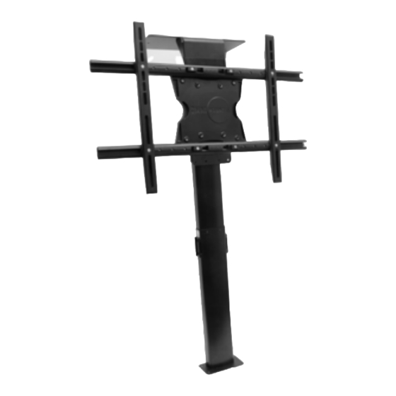
Page 1: Universal Adapter
Lift 42 Motorized Flat Panel Lift System with Universal Adapter. ULN # 10235 PN # Lift 42 = L1-10235-PRO-101008vE INSTRUCTION MANUAL IMAGES MAY DIFFER FROM ACTUAL PRODUCT. - Page 2 (800.668.6848) or info@omnimount.com. You must supply a copy of your original receipt. If your product must be shipped to OmniMount for inspection, you will be responsible for the shipping charges. Replacement product shipped to you will be returned freight pre-paid.
- Page 3 Contents Contents Base Mount Lift Column Bayonet Bracket Screen Support Top Plate Control Box Remote Control IR Receiver/Control switch Corner brackets Universal Adapter Vertical Extension Rails and covers Screen Adapter Motor cable Power cable...
- Page 4 Contents Monitor Kit: Parts M-A through M-N are used to connect the TV to the universal adapter. Spacers may be necessary for a proper fit with recessed mounting holes or to allow access to TV inputs. Monitor Kit L-U-vA Pouch # Part # Description Philips screws M4 x 15mm...
-
Page 5: Lift Column
Before Installation Prior to enclosure construction and lift assembly, please read through the below warnings and recommendations to ensure a successful installation! PINCH POINT WARNING! • Improper construction of lift enclosure can create dangerous pinch points. It is the responsibility of the installer to ensure the intended use of this product does not create hazardous pinch zones. - Page 6 Before Enclosure Construction! Assemble lift mechanism and connect the TV to be used in the install to determine dimensions for the lift enclosure prior to construction. Be sure to leave room for adjustments If necessary. An out of cabinet assembly of the mechanism can be done using steps 1,4,6,8,9 and 10 in order.
- Page 7 Measurements Required For Cabinetry Dimensions Use previous page to find the minimum INTERIOR dimensions for custom enclosures. Width Height Depth...
- Page 8 Step 1 Attach the Base Bracket (1) to the Lift Column (2): • Using the small Hex wrench and 6mm x 20mm screws (O), connect the base bracket to the lift column. Note that one side is counter sunk to ensure flush installation of screws.
-
Page 9: Bayonet Bracket 1
Step 2 Attach the Bayonet Bracket (3) to the enclosure: • Using the #10 x ¾” screws (Q), attach the bracket so that the top edge of the brackets back plate is 20” above the bottom mounting surface (the bottom of the cabinet or top of the spacer block if used). - Page 10 Step 3 Secure Lift Column and Base Bracket in enclosure: • Gently glide the lift column into place on the bayonet bracket so that the tapered slots on the column are secured to the extrusions on the bracket. Gently push down until the base bracket is touching the bottom of the enclosure.
-
Page 11: Screen Support
Step 4 Connect Screen Adapter (12) to the Screen Support (4): • Use the large hex wrench to secure the screen adapter to the screen support using four 3/8-16 x ¾” screws (S). Depending on TV size and mounting hole pattern the screen adapter can be vertically adjusted for optimal fit. - Page 12 Step 5 Initialize the lift system: • Connect the motor cable to the control box and “pigtail” on the lift column as shown in figures A and B. • Connect the IR receiver/control switch and control box power as shown in figures C and •...
-
Page 13: Top Plate(
Step 6 Attach the Screen Support(4) and Top Plate(5) to the Lift Column(2): • Before attaching the top plate ensure that the rubber guide on the “pigtail” is secured in the square cutout on what will be the front of the lift column (fig. A). Failure to do so may result in damage to the wire. - Page 14 Step 7 Attach lift assembly to enclosure base: • Using a level on the top plate ensure that the lift column and assembly are level within the enclosure. Gently tap the base of the column left or right to bring the top plate level. •...
-
Page 15: Universal Adapter
Step 8 Attach the Universal Adapter to the TV: • Place the TV face down on a protected surface. • For larger TV’s, the vertical rails may need swapped out for the longer included rails. Rails are swapped by removing 2 Phillips screws per rail. •... -
Page 16: Screen Adapter
Step 9 Connect the TV and universal adapter to the lift column: • Partially install two ¼-20 x ½” (W) hex screws into the top rear of the universal adapter (fig. A). • Lift and lock TV into position on screen adapter (fig. B). •... - Page 17 Step 10 Install universal adapter rail covers: • Carefully attach the correct plastic covers to the universal adapter.
- Page 18 • Improper use of guide pins may result in property damage or injury. If you are unsure or are having difficulty using the guide pins with a floating top, contact a professional installer or OmniMount customer service. Enclosure lid Guide pins...
- Page 19 Guide Pin/Top Plate Template...
- Page 20 OmniMount Systems, Inc. 8201 South 48th Street Phoenix, AZ 85044-5355 1-800-MOUNT-IT 1-800-668-6848 www.omnimountpro.com Thank you for purchasing an OmniMount product.