Table of Contents
Advertisement
J_
Ie J Y2
owners
manual
MODEL NO.
161.216300
Caution:
Read Rules For
Safe Operation
and Complete
Operating Test
Procedures
Carefully
IIIII
IIIII .I
I III illll U
III!IIII
INE ANALYZ
FOR
12
VOLT
SYSTEMS
OPERATING
INSTRUCTIONS
SAFETY
RULES
TUNE-UP
PROCEDURES
I IIIIIII
III III
I
PRINTED
IN U.S.A,
REPAIR
PARTS
III
II
SEARS, ROEBUCK
AND CO. U.S.A.
CH!CAGO,
ILLINOIS
60684
.
II
IJ
IIIII[
I
.
I
IIIIIIIIIIIIII IIIWHIIIIIIIII
II
II
L
IllIII
. . I II I
,JJ .....
II
IJLJIIJIII I III1[
.
l Ill . .
I
I iilliiII
III II
I I IIIIIIIIIIIIIIIIIIII
2-168302
Advertisement
Table of Contents

Related Manuals for Sears 161.216300


Summary of Contents for Sears 161.216300
- Page 1 Ie J Y2 owners manual MODEL NO. 161.216300 INE ANALYZ VOLT SYSTEMS OPERATING INSTRUCTIONS Caution: SAFETY RULES Read Rules For Safe Operation TUNE-UP PROCEDURES and Complete Operating Test Procedures REPAIR PARTS Carefully IIIII IIIII .I I III illll U III!IIII IllIII .
- Page 2 RULES FOR SAFE AUTOMOTIVE TESTING WARNING -- READ CAREFULLY Read this OperaUon Manual and these Rules for Safe Automotive Testing carefully. Failure to follow instructions and safety rules could result in sedous bodily injury and/or damage to the Instrument. Before starting the engine, set the parking brake and place the Keep hands, hair, neckbe, loose clothing and test leads well gear selector in NEUTRAL on standard...
-
Page 3: Engine Analyzer Controls, Connections & Accessories
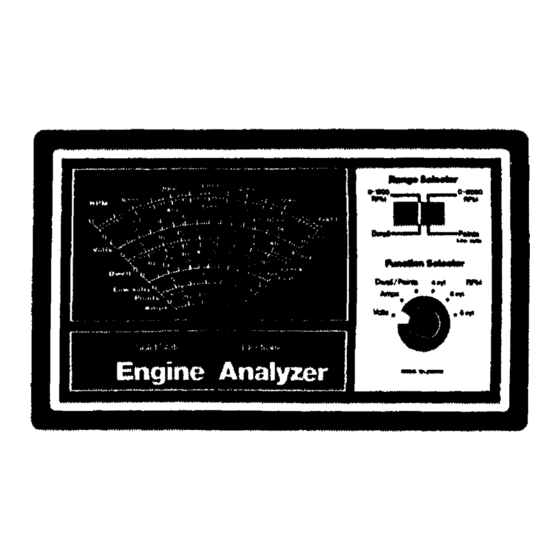
ENGINE ANALYZER ANGE SELECTOR This selects the Dwell or Points/Low Volts lunctions CONTROLS, CONNECTIONS, of the analyzer, as well as the 0-1200 or 0-6000 RPM AND ACCESSORIES ranges. BATTERY LEAD DESCRIPTION. Model 161.2163 Engine The Red clip is connected to the positive (+) battery Analyzer has a clearly labeled meter and controls as terminal,... - Page 4 1+ GM HEI ADAPTOR The GM HEt Adaptor is used to provide Connection to the "TACH" terminal on GM HEt systems. See Figure 7 for typical installation. 2+ GM DIAGNOSTIC ADAPTOR The GM Diagnostic Adaptor is used to make con- nection to vehicles equipped with the GM Diagnostic Connector, (1976 - 1982).
- Page 5 -)TO IGNITION SWITCH DELCO WITH INTEGRAL COIL INSERT DIAGNOSTIC ADAPTER AOAPTER _'. _,._ REMOVE PRIMARY TACH CONNECTION GREEN Clip CAP FROM GREEN Delco HEr 1974. 1985 TACH TEST CONNECTOR FIGURE PRIMARY TACH CONNECTION GREEN Clip Toyota IIA (Integraled Ignition Assembly) 1983 - 1985 F}GURE t0 Note:...
- Page 6 ELECTRICAL SYSTEM-- Check the alternator/generator output rating as listed on its color-coded tag or _tamped on the alternator/ PRELIMINARY CHECKS generator frame. Forexample, 60A or IOOAindicates a 60 Ampere or 100 Ampere alternator/generator. This INTRODUCTION. Before performing electrical rating should equal or exceed the manufacturer's system tests, carefully read the following information.
-
Page 7: Cranking Circuit Voltage Loss Test
CRANKING CIRCUIT VOLTAGE LOSS TEST, CHARGINL_ _Y_ 1_M VUL i/_L_I;: It is the function of the charging system to keep the battery THE CRANK1NG CIRCUIT VOLTAGE LOSS TEST charged when the engine is running and to power the checks for voltage losses in the cranking system, rest of the vehicle's electrical load requirement (ignition, 1. - Page 8 MISCELLANEOUS VOLTAGE TESTS 13. Shut off all accessories, return the engine to curb idle, and shut it off. This analyzer can perform many of the voltage tests called 14. If the results obtained in Steps 5, 10, or 12 are signifi - out in the vehicle service mandal,...
- Page 9 to) L;onnect [ne analyzer to the vehicle as shown in (e) It dwelt is within specification no adjustment is Figures 1 and 4. necessary. (c) Function Selector - Dwell/Points ..(d) Range Selector - Points/Low Volts NOTE NOTE There is a direct relationship between dwell end timing. However, it is onlya one way relationship.If you change When testing a vehicle with dual points, alternately the dwell angle of the breaker points, you will auto-...
- Page 10 Getector a5 follows: 6. Reassemble distributor a nd recheck dwellreading withengine operating a tidlespeed. For RPM measurement, Repeat steps 5 and6if necessary. Function Selector - RPM (4, 6, or 8 cylinder match the engine under test) e Range Selector- 0-1200 for idle RPM 0-6000 for High RPM For MiC So{enoid dwell measurement, Function...
- Page 11 [ ..... KEY NO. PART NO. DESCRIPTION ..J, , ,, , ,,,,,j,, , ,,i ..i000-252 Ampere shunt 38-728 Cable Assembly, Ampere shunt 38-729 Cable Assembly, Green Clip 400-861 Case, bottom 270-117 Screw, Case Self-tap. #6-20 x 1" 38-727 Cable Assembly, Red and Black clip Switch Decal...
- Page 12 IIII I IIIIIIIIII ....IIIIIIIIIIIIIIII I III IIIlI ENGINE owners ANALYZER manual Now that you have purchased your ENGINE ANALYZERt should a need ever exist for repair parts or servicer simply contact Sears, Roebuck and Co. stores. Be sure to pro- vide all pertinent facts when you call or visit.