Table of Contents
Advertisement
Operator's
Manual
I CRAFTSMAN°I
_ PROFESSI
ONAL_
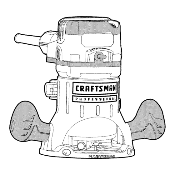
14.0 Amp, Variable Speed
2-1/2 Peak HP Router Combo
With Fixed Base and Plunge Base
Model No. 320.27680
WARNING:
To reduce the risk of
injury, the user must read and
understand
the Operator's
manual
before using this product.
c us
• WARRANTY
• SAFETY
• UNPACKING
• DESCRIPTION
• OPERATION
• MAINTENANCE
• TROUBLESHOOTING
• ESPANOL
Sears Brands Management
Corporation,
Hoffman
Estates,
IL 60179
U.S.A.
www.craftsman.com
Advertisement
Table of Contents

Related Manuals for Craftsman 320.27680


Summary of Contents for Craftsman 320.27680
- Page 1 Operator's Manual I CRAFTSMAN°I _ PROFESSI ONAL_ 14.0 Amp, Variable Speed 2-1/2 Peak HP Router Combo With Fixed Base and Plunge Base Model No. 320.27680 c us • WARRANTY • SAFETY • UNPACKING • DESCRIPTION WARNING: To reduce the risk of •...
- Page 2 View and Part List page 42-48 Sears Repair Parts Phone Number Back Cover CRAFTSMAN PROFESSIONAL ONE YEAR LIMITED WARRANTY FOR ONE YEAR from the date of purchase, this product is warranted against any defects in material or workmanship. With proof of purchase, defective product will be replaced free of charge.
- Page 3 The purpose of safety symbols is to attract your attention to possible dangers. The safety symbols and the explanations with them deserve your careful attention and understanding. The symbol warnings do not, by themselves, eliminate any danger. The instructions and warnings they give are no substitutes for proper accident prevention...
- Page 4 SAVE THESE INSTRUCTIONS Some of these following symbols may be used on this tool. Please study them and learn their meaning. Proper interpretation of these symbols will allow you to operate the tool better and more safely. SYMBOL NAME DESIGNATION/EXPLANATION Volts Voltage Amperes...
-
Page 5: Power Tool Safety Warnings
GENERAL POWER TOOL SAFETY WARNINGS WARNING: Read all safety warnings and instructions. Failure to follow the warnings and instructions may result in electric shock, fire and/or serious injury. • Know your power tool. Read the operator's manual carefully. Learn the applications, as well as the specific potential... -
Page 6: Personal Safety
PERSONAL SAFETY • Stay alert, watch what you are doing and use common sense when operating a power tool. Do not use the tool while tired or under the influence of drugs, alcohol, or medication. A moment of inattention while operating power tools may result in serious personal injury. -
Page 7: Service Safety
Always check the tool for damaged parts before use. Before further use of the tool, a guard or other part that is damaged should be carefully checked to determine if it will operate properly and perform its intended function. Check for misalignment or binding of moving parts, breakage of parts, and any other condition that may affect the tool's operation. - Page 8 Use only identical replacement parts when servicing a tool. Follow the instructions in the maintenance section of this manual. Use of unauthorized parts or failure to follow maintenance instructions may create a risk of electric shock or injury. SPECiFiC SAFETY RULES FOR ROUTER •...
- Page 9 1-1/4 inches. To use cutter bits with a larger diameter, install and use a sub-base with a larger diameter opening (sold separately at Sears stores or other Craftsman outlets). • Do not use large router cutter bits for freehand routing.
- Page 10 _h, WARNING: Your router should never be connected to the power source when you are assembling parts, making adjustments, installing or removing bits, cleaning, or when it is not in use. Disconnecting the router will prevent accidental starting, which could cause serious personal injury. When unpacking the box, do not discard any packing materials...
- Page 11 Plunge Base Vacuum Port for Plunge Base Vacuum Port for Fixed Base 2 Chip Shields 2 Thumb Screws (for attaching port to plunge base) © 1/4-in. Collet/Nut Edge Guide Depth-Adjustment Wrench Collet/Nut Wrench 27683 ManuaLRevised_11-0120 Page 11...
- Page 12 I ,] _]_II]_III[,]_] KNOW YOUR ROUTER (Fig. 1) NOTICE: Before attempting to use your router, familiarize yourself with all of the operating features and safety requirements. Your router has a precision-built electric motor and it should only be connected to a 120-volt, 60-Hz AC only power supply (normal household current).
-
Page 13: Product Specifications
WARNING: Do not allow familiarity with the router to cause a lack of alertness. A fraction of a second of carelessness is enough to cause severer injury PRODUCT SPECIFICATIONS Rating 14.0 Amps No Load Speed 10000-25000 RPM Peak HP 2-1/2 Input 120V, 60Hz AC Collets/Nuts... - Page 14 Protective Plunge Post Bellows protect guideposts from woodchips, dust, and moisture. Spindle Lock for easy 1-wrench bit changes. Includes 1/4 and 1/2 inch Self-Releasing Collets/Nuts for use with a wide variety of 1/4 in. and 1/2 in. router bits, sold separately. 10.
- Page 15 1-1/4 inches. To use cutter bits with larger diameters, use sub-bases with larger openings, sold separately at Sears stores or other Craftsman outlets. WARNING: Always turn the motor off and unplug the router before making any adjustments or installing accessories.
- Page 16 Press the spindle-lock button to engage Collet and lock the spindle shaft and collet/nut Spindle Lock (Fig. 3) Place the wrench on the collet/nut turn it counterclockwise to loosen the collet/nut slightly so it can accept cutter bit shank. Insert the cutter bit shank into the collet/ nut assembly as far as it will go, then back the shank out until the cutters are...
- Page 17 NOTICE: See the instructions for removing the motor housing from the plunge base. Place the router motor upside down on its top cap with the collet/nut pointing up. Press the spindle-lock button to engage and lock the spindle shaft and collet/nut (Fig.
- Page 18 _1, WARNING: Always wear safety goggles or safety glasses with side shields during power tool operations, or when blowing dust. If operation is dusty, also wear a dust mask. Always make sure that the cutter bit shank, collet/nut and motor spindle are clean and free of woodchips, dust, residue, grease and rust before installing a cutter bit or collet/nut.
- Page 19 After all adjustments are made, close the motor clamp securely. To install the Motor in Plunge Base (Fig. 5a) 1. Turn the motor off and unplug the Fig. 5a router from the power source. Place the plunge base on a fiat surface.
-
Page 20: Adjusting The Depth Of Cut
Lift the motor straight up and out of the base, sliding the motor housing "slot" (C) free from the pin in the plunge base. Set the motor upside down on its top cap with the collet/nut pointing up, and remove the cutter bit. WARNING: Always remove the cutter bit from collet/nut when the router is... - Page 21 The depth indicator ring (D), located on the fine adjustment dial is marked in 1/64th inch increments. Turning the fine adjustment dial clockwise 180 ° (1/2 turn), lowers the cutter bit 1/16 inch. One full turn clockwise 360 ° lowers the bit 1/8 inch. The system allows a maximum of 7 full 360 °...
- Page 22 Apply an even, downward pressure on the plunge action until the cutter bit reaches the desired depth, then move the plunge-lock lever "down" to the locked position. To raise the bit and the plunge action, unlock the plunge-lock lever. The plunge action will automatically retract from the workpiece return to the raised position.
- Page 23 NOTICE: When making depth adjustments on the plunge base, the motor clamp should always be closed securely. Using the Depth-Stop Turret to Set Up Deep Cuts (Fig. 10) NOTICE: Making a single deep cut is never advisable. Smaller diameter cutting bits are easily broken by too much side thrust and torque.
- Page 24 TOGGLE "ON/OFF" SWITCH (Fig. 11) Your router motor is turned "ON" and "OFF" Fig. 11 with the toggle switch located on the top cap of the motor housing. The left side of the toggle switch hood (as you face it) is marked "O" for "OFF" and the right side (as you face it) is marked "1"...
- Page 25 To attach the edge guide to the fixed or Fig. 14 plunge base, simply insert the edge guide rods into the edge-guide mounting slots either from the left or the right. For fix base Tighten the lever on the left by turning it clockwise to secure the edge...
- Page 26 Variable Speed Selection Chart Never exceed these bit speeds Cutting-Bit Diameter Maximum Speed UP to 1 in. (25mm) 1-1/4 in. to 1-3/4 in. (31-44mm) 2 in. to 2-1/2 in. (50-63.5mm) 2-3/4 in. to 3 in. (69-75mm) 3 in. to 3-1/2 in. (75-90mm) Reduce the speed when using extra large bits (with a cutting diameter 1 inch or greater) or heavy cutter bits.
-
Page 27: Edge Routing
Much of routing is a trial-and-error process of making various adjustments, followed by test cuts. To avoid ruining good material, make test cuts on scrap materials. How you place your router onto a workpiece (starting the cut) with a fixed base or a plunge base depends on the type of routing you are going to produce:... - Page 28 To begin the cut, gradually feed the cutter bit into the edge of the workpiece. When the cut is complete, turn router motor "OFF" and allow the cutter bit come to a complete stop before removing it from the workpiece. Unplug the router from the power source, and inspect the finished cut.
- Page 29 INTERNAL ROUTING WITH PLUNGE BASE (Fig. 20) 1. With the depth-of-cut set, and the plunge Fig. 20 action locked in the raised (Up) position, turn the router motor "ON" and allow the router motor to reach the selected speed (see Fig. 20). To begin your cut, unlock the plunge-lock lever and gently lower the plunge action evenly into the workpiece.
- Page 30 When freehand routing: Draw or lay out the pattern on the workpiece. Choose the appropriate bit. Follow the instructions for INTERNAL ROUTING, and rout the pattern in two or more passes. Do not exceed 1/8 in. depth of cut in a single pass. This will help provide better control, as well as serve as a guide on the next passes.
-
Page 31: Router Feed Direction
NOTICE: The size (diameter) of the pilot that Fig. 22a is used determines the maximum cut width that can be made with the pilot against the workpiece edge (the small pilot exposes the entire bit; the large one reduces this amount by 1/16 in.). - Page 32 WARNING: Kickback causes the power tool to jerk back toward the user, causing possible loss of control and serious injury. Always take precautions against kickback as described in this operator's manual. DIRECTION OF FEED - INTERNAL CUTS (Figs. 24 and 24a) When making an internal cut, such as a Fig.
- Page 33 FEEDING TOO QUICKLY (Fig. 25} Clean and smooth cuts can only be achieved Fig. 25a when the cutter bit is rotating at a relatively high speed, taking very small bites, producing Bit Shank tiny, clean-cut chips. Forcing the feed of the cutter bit forward too quickly slows the rotational speed of the cutter bit, and the bit takes bigger bites as it...
-
Page 34: Dust Collection
shield from the plunge base, simply loosen -Fig. 26a the screw and take the chip shield off the base (Fig. 26a). _1, WARNING: The chip shield helps to keep dust and chips away from the operator; they will not stop objects larger than woodchips that may be thrown from the bit. - Page 35 TO ADJUST DEPTH WITH DEPTH-ADJUSTMENT WRENCH (Figs. 28, 28a and 28b) NOTICE: The Depth-Adjustment wrench supplied is used to adjust the depth when Fig. 28 the router is fixed to the router table (Model No. 320. 28160), sold separately. WARNING: Always read and follow all directions for mounting...
- Page 36 Turn off the router. Loosen the router motor clamp. Lock the plunge-depth locking lever. Insert the wrench into the adjusting hole on the tabletop. Turn the depth rod on the router clockwise with the wrench to move the collet/nut up, or counterclockwise to move the collet/nut down.
-
Page 37: Maintenance
All other parts represent an important part of the double-insulation system and should be serviced only by a qualified Craftsman service technician. WARNING: For your safety, always turn off the switch and unplug the router motor from the power source before performing any maintenance cleaning. - Page 38 REPLACEMENT OF CARBON BRUSHES (Fig. 29) Replacement brush sets are Fig. 29 available through Sears Parts and Repair Centers. Unplug the router motor before inspecting replacing brushes. Replace both carbon brushes when either has less than 1/4 in. length of carbon remaining, or if the...
- Page 39 1/2 in. collet. WARNING: The use of attachments or accessories that are not recommended for this tool might be dangerous and could result in serious injury. Sears and other Craftsman outlets offer a large selection of Craftsman router accessories designed for specific routing applications.
- Page 40 straight 1/8-in. 3/8- n 1/4-in. straight l i straight straight ..3/4-in. [. 5/16-in. i[i} 1/2-in. straight straght iLii straight dovetail 3/8-in. dove tail 1/2-in. dove tail round nose 1/2-in. round nose 1/2-in. 90 d v groove v groove 1/2 x 1-in. 3/8x1/2-in.
- Page 41 1/2-in. bead and cove bead cove 1/16-in. & bead classic cove with bead 1/4-in. roman ogee Roman ogee ¸ 3/8-in. rabbeting rabbeting 1/4-in. veining veining 1/2-in. core box core box 1/2-in. mortising mortising 1/4-in. panel pilot panel pilot 1-3/8-in. 45 o chamfer chamfer 27683 ManuaLRevised_11-0120 Page 41...
- Page 42 14.0 Amp Combo Pro Router Model No. 320.27680 The Model Number will be found on the Nameplate attached to the motor unit. Always mention the Model Number when ordering parts for this tool. 27683 Manual_Revised_11-0120 Page 42...
- Page 43 14.0 Amp Combo Pro Router Model No. 320.27680 The Model Number will be found on the Nameplate attached to the motor unit. Always mention the Model Number when ordering parts for this tool. 27683 ManuaLRevised_11-0120 Page 43...
- Page 44 14.0 Amp Combo Pro Router Model No. 320.27680 The Model Number will be found on the Nameplate attached to the motor unit. Always mention the Model Number when ordering parts for this tool. 27683 ManuaLRevised_11-0120 Page 44...
- Page 45 14.0 Amp Combo Pro Router Model No. 320.27680 The Model Number will be found on the Nameplate attached to the motor unit. Always mention the Model Number when ordering parts for this tool. 3321134000 Rear Cover 3123313000 Transparent 5610220000 Thread Forming Screw 5610017000 Thread Forming Screw 4900278000...
- Page 46 5630179000 5620069000 Screw 2823121000 Collet assembly 5620061000 Screw 3421190000 Spindle lock cover 5620041000 Screw 3320460000 Adjusting Knob 3123281000 Indicator 3550854000 Shaft 3320274000 Handle 5620024000 Hexagon Socket Screw 2823165000 Mounting 3121637000 Chip Shield 2823122000 Lever Assembly 3703872000 Plate 5630015000 Prevailing Torque Hexagon 5660005000 E Ring 3660498000...
- Page 47 5650014000 Plain Washer 3660313000 Spring 3550913000 Depth Stop Bar 3703949000 Clip 3123453000 Sleeve 3123453000 Sleeve 3123434000 Depth Indicator 3550083000 Depth Adjusting Bolt 3402338000 Lock Bolt 3123498000 5630016000 Hexagon Nut 3123497000 Cover 2823166000 Plunge Frame 5620039000 Screw 5650007000 Spring Washer 3420398000 Plunge Lock Lever 3660254000 Torsion Spring...
- Page 48 3123500000 Suppo_ Plate 3550588000 Guiding 3703925000 Fence 5620050000 Screw 5650015000 Spring Washer 5650013000 Washer 3123344000 Chip Shield 3123286000 Vaccum Adapter 3402471000 Wrench 3126054000 Handle Sleeve 27683 Manual_Revised_11-0120 Page 48...
- Page 49 27683 Manual_Revised_11-0120 Page 49...
- Page 50 27683 Manual_Revised_11-0120 Page 50...
- Page 51 27683 Manual_Revised_11-0120 Page 51...
- Page 52 Your Home For troubleshooting, product manuals and expert advice: managemylife www.managemylife.com For repair - in your home - of all major brand appliances, lawn and garden equipment, or heating and cooling systems, no matter who made it, no matter who sold it! For the replacement parts, accessories and owner's manuals that you need to do-it-yourself.