Table of Contents
Advertisement
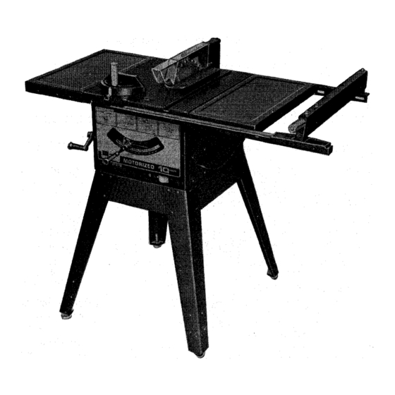
]Sears]
owners
manual
MODEL NO.
113.29580
SAW ONLY
113.295820
SAW WITH LEGS AND
TWO TABLE EXTENSIONS
Serial
Number
Model and serial
number may be found
at the right-hand side
of the base.
You should record both
model and serial number
in a safe place for
future use.
CAUTION:
Read
GENERAL
and
ADDITIONAL
SAFETY
INSTRUCTIONS
carefully
CRAFTSMAN°
IO-INCH
MOTORIZED
TABLE SAW
• assembly
• operating
• repair
parts
Sold by SEARS,
ROEBUCK
AND
CO., Chicago,
IL. 60684
U.S.A.
Part No, 62657
Printed in U.S.A.
Advertisement
Table of Contents

Related Manuals for Craftsman 113.295820


Summary of Contents for Craftsman 113.295820
- Page 1 TWO TABLE EXTENSIONS Serial Number Model and serial number may be found at the right-hand side of the base. You should record both CRAFTSMAN° model and serial number in a safe place for future use. IO-INCH MOTORIZED CAUTION: TABLE SAW...
- Page 2 FULLONEYEAR WARRANTYONCRAFTSMAN TABLESAWS If within one year from the date of purchase, this Craftsman Table Saw fails due to a defect in material or workmanship, Sears will repair it, free of charge. Warranty service is available by simply contacting the nearest Sears store or Service Center throughout the United States.
-
Page 3: Blade Guard
ADDITIONAL SAFETY INSTRUCTIONS FOR TABLE SAWS WARNING: YOUR SAFETY, thrown back at the operator at excessive speed. This OPERATE YOUR SAW UNTIL IS COMPLETELY can usually be avoided by keeping the guard and ASSEMBLED AND INSTALLED ACCORDING TO THE spreader place all "THRU-SAWING"... - Page 4 16. NEVER FEED MATERIAL INTO CUTTING B. Never use grinding wheels, abrasive cut-off wheels, TOOL FROM THE REAR OF THE SAW. An accident friction wheels (metal slitting blades) wire wheels or and serious injury could result. buffing wheels. 17. THINK SAFETY. 11.
-
Page 5: Table Of Contents
If yoursawis for use onless than150voltsit has a plug If the outlet you are planning to use for this saw is of the thatlooks likebelow. two prong type DO NOT REMOVE OR ALTER 3-PRONG PLUG GROUNDING PRONG IN ANY MANNER. Use an adapter as shown and always connect the grounding lug to a known ground. - Page 6 UNPACKING AND CHECKING CONTENTS WARNING: YOUR SAFETY, NEVER CONNECT PLUG TO POWER SOURCE OUTLET UNTIL TOOLS NEEDED ASSEMBLY STEPS ARE COMPLETE, HAVE READ AND UNDERSTAND THE SAFETY OPERATIONAL INSTRUCTIONS. Hammer Medium Screwdriver Small Screwdriver LIST OF LOOSE PARTS No. Part Name Qty.
- Page 7 Lockwasher, 5/16 in. ExternalType (approx.dia.of hole5/16 in.) ....WingScrew,1/4 in.-20 x 1/2 in. long ... Hex Hd. Screw, 5/16- 18 x 1-1/2 in. long ..Hex Hd. Screw,5/16 - 18 x 1 in. long ..The following parts are included with Model 113.295820 (NOT SUPPLI ED IN CANADA) No.
- Page 8 If the insert is BELOW the table surface, remove insert and bend the tabs (with pliers) enough to make the insert ABOVE the table surface. Re-install insert and adjust as described under "2". DO NOT TIGHTEN SCREW TO THE POINT WHERE IT DEFLECTS THE INSERT.
- Page 9 EXT. LOCKWASHER HEX. HEAD SCREW 1 IN. LONG 5/16 tN FLAT WASHER INSTALLING RIP FENCE GUIDE BARS From among loose parts find following hardwa re: 5/16 iN. 2 Hex. Head Screws, 5/16 in.- 18 x 1-1/2 in. long REAR GUIDE 2 Hex.
- Page 10 SCREWS THROUGH HOLESMARKED "X" ASSEMBLING STEEL LEGS NOTE: Steel Legs are furnished with Model 113.295820. From among the loose parts, find the following Hardware: ..24 Truss Head Screws; 1/4 in. - 20 x 5/8 in. long (top SIDE STIFFENER of screw is rounded) 24 Lockwashers, 1/4 in.
- Page 11 ALIGNING TABLE EXTENSIONS 1. "Tap" extensions upwards or downwards, using a block of wood and a hammer until they are even with top of saw table. Be sure end of extensions are even with front BLOCK OF WOOD edge of saw. 2.
- Page 12 SCREWS rip fence must be PARALLEL with the sawblade and Miter Gauge grooves... Move fence until it is along side of groove. Do NOT LOCK IT. It should be parallel to groove. If it is not; FENCE HEAD Loosen the two "'Hex. Head Screws.'"...
- Page 13 ADJUSTING RIP SCALE POINTER 1. Turn ELEVATION crank counterclockwise until blade is up as high as it will go. LOCK HANDLE "" IMPORTANT: BLADE must be SQUARE (90 ° ) to TABLE, in order to ALIGN rip fence. 2. Position fence on right side of sawblade so that touches the sides of the teeth .
- Page 14 Lay a piece of flat straight wood and a square on saw table and rotate the SPREADER SUPPORT until the bracket is aligned with square. MAKE SURE END OF SUPPORT, BRACKET ROD ARE EVEN . .. using an 1/8 in. setscrew wrench, TIGHTEN THE SET SCREWS ONLY.
- Page 15 GETTING TO KNOW YOUR BLADE GUARD ANTI-KICKBACK PAWLS MITER GAUGE LOCK HANDLE SAW BLADE MITER GAUGE SPREADER RIP FENCE HEAD MITER GAUGE TABLE INSERT HOLES ATTACHING FACING TILT CRANK RIP FENCE LOCK HANDLE ELEVATION CRANK RESET ON-OFF SWITCH ON-OFF SWITCH CAUTION: Before turning switch on, make sure the blade...
- Page 16 RESET BUTTON See "Motor Specifications NOTE: When bevel crosscutting, attach facing so that it Electrical Requirements" section, "Motor Safety extends to the right of the miter gauge and use the miter Protection." gauge in the groove to the right of the blade. AUXILIARY FACING ELEVATION CRANK...
-
Page 17: Work Helpers
/ ",,,-,,/ 4qEMOVING AND INSTALLING SAWBLADE WARNING: FOR YOUR OWN SAFETY, TURN SWITCH "OFF" REMOVE PLUG FROM POWER SOURCE OUTLET BEFORE REMOVING INSTALLING SAWBLADE. A. Remove insert. B. Place ARBOR wrench on flat surfaces of saw ARBOR . . . ARBOR NUT wrench on nut . - Page 18 THESE EDGES MUST BE PARALLEL h.4_3/4_ 45° NOTCH 1-5_8 "_[___L.T_T WORKPIECE ,/411,/4 --'t 1/4 3//8 NOTE: dimensions 'n inches 3//8 PLYWOOD PUSH STI CK NOTE: _,11dimensions in inches PUSH BLOCK PUSH STICK AND PUSH BLOCK PLYWOOD Make the Push Stick using a piece of 1 x 2. Make the Push Block using a piece of 3/8 in.
-
Page 19: Repetitive Cutting
When cutting long workpieces, also invert AUXILIARY FENCE/WORK SUPPORT and position it on of the guide bars to support the workpiece as near to the end as possible. Use the Hold-Down Clamp (Optional Accessory) on the miter gauge for greater accuracy. -
Page 20: Miter Cutting
MITER CUTTING MITER CUTTING is known as cutting wood at an angle other than 90 ° with the edge of the wood. Follow the same procedure as you would for crosscutting. Adjust the miter gauge to the desired angle, and lock it. The miter gauge may be used in either of the grooves in the table. - Page 21 ALWAYS SUPPORT LONG WORKPIECES RIPPING RIPPING is know as cutting a piece of wood with the grain, or lengthwise. This is done using the rip fence. Position the fence to the desired WIDTH OF RIP and lock in place. Before starting to rip, be sure Rip Fence is parallel...
- Page 22 When WIDTH OF RIP is NARROWER than2 in., the push stick CANNOT be used because the guard will interfere... USE the AUXILIARY FENCE and PUSH BLOCK. Attach auxiliary fence to rip fence with two "C" clamps. Feed the workpiece by hand until the end is approx. 1 in. from the front edge of the table, Continue to feed using the PUSH BLOCK.
-
Page 23: Cutting Panels
AUXILIARY FENCE/ WORK SUPPORT CUTTING PANELS When cutting panels (whenever fence is positioned outside table surface), ALWAYS AUXILIARY F ENCE/WOR K SUPPORT. Unlock fence and raise rear end. Position AUXILIARY FENCE as shown and attach with two "C" clamps. RABBETING Rabbeting is known as cutting out a section of the corner of a piece of material. -
Page 24: Blade Tilt, Or Squareness Of Blade To Table
HEELING ADJUSTMENT or PARALLELISM OF SAWBLADE TO MITER GAUGE GROOVE While cutting, the material must move in a straight line PARALLEL to the SAWBLADE . . . therefore both the miter gauge GROOVE and the FENCE must be PARALLEL tothe SAWBLADE. If the sawblade IS NOT parallel to the miter gauge groove, the blade will bind at one end of the cut. - Page 25 If blade IS SQUARE to table; Check pointer If POINTER DOES NOT point to the "O" mark on the bevel scale; B. Loosen screw and adjust pointer.., using medium screwdriver. BLADE COVERED WITH PIECE OF CARDBOARD If blade is NOT SQUARE to table.., the 90 °...
-
Page 26: Blade Elevation
Frequently blow out any dust that may accumulate inside teeth. the saw cabinet and the motor. Frequently clean your cutting tools with Craftsman Gum and Pitch Remover. A coat of automobile-type wax applied to the table will help to keel_ the surface clean and allow workpieces to slide more freely. - Page 27 LUBRICATION Elevation screw threads and pivot nut. (First Clean with The saw motor bearings have been packed at the factory Craftsman Gum & Pitch Remover.) with proper lubricant and require no additional lubrication• The following parts should be oiled occasionally with SAE 3.
-
Page 28: Tilt And Elevation Mechanism
TROUBLE SHOOTING WARNING: FOR YOUR OWN SAFETY, TURN SWITCH "OFF" AND ALWAYS REMOVE PLUG FROM POWER SOURCE OUTLET BE FOR E TROUBLESHOOTING. TROUBLE SHOOTING -- GENERAL TROUBLE PROBABLE CAUSE REMEDY Blade out of balance. Excessivevibration. Discard Blade and use a different blade. Miter gauge not adjusted Cannot make square See "Adjustments"... - Page 29 TROUBLE SHOOTING -- MOTOR (Continued) REMEDY TROUBLE PROBABLE CAUSE 1. Request voltage check from the power company. Motor starts slowly 1. Low voltage will not trip relay. or fails to come up 2. Have motor repaired or replaced. 2. Windings burned out to full speed.
- Page 30 PARTS LIST FOR CRAFTSMAN 10 INCH MOTORIZED MODEL NO. 113.29580 & 113.295820 31" 35 34 Figure 1...
- Page 31 PARTS LIST FOR CRAFTSMAN 10 INCH MOTORIZED MODEL NO. 113.29580 & 113.295820 Always order by Part Number -- not by Key Number FIGURE 1 PARTS LIST Part Part Description Description 62540 Bar Assembly, Fence Guide 62523 Gauge Assembly, Miter (See Figure 4)
- Page 32 PARTS LIST FOR CRAFTSMAN 10 INCH MOTORIZED MODEL NO. 113.29580 & 113.295820 L ..T-° 17 16 *If this part is removed, discard and replace with a new retaining ring. Figure 2...
- Page 33 PARTS LIST FOR CRAFTSMAN 10 INCH MOTORIZED MODEL NO. 113.29580 & 113.295820 FIGURE 2 PARTS LIST Part Part Description Description 62628 Table, Saw 62651 Rod, Motor 805297-1 Screw, Flat Hd. 5/16-18 × 1-1/4 60076 Washer, .505 x 1-1/8 x 1/16 STD 511107 *Screw, Pan Hd.
- Page 34 PARTS LIST FOR CRAFTSMAN 10 INCH MOTORIZED MODEL NO. 113.29580 & 113.295820 FIGURE 3 - 62525 FENCE ASSEMBLY Part Description 62525 Fence Assembly, Rip 62524 Handle STD 551031 *Washer, 21/64 x 1/2 x 1/32 62534 Indicator, Fence 60049 *Screw, Pan Hd. Type "T"...
- Page 35 PARTS LIST FOR CRAFTSMAN 10 INCH MOTORIZED MODEL NO. 113.29580 & 113.295820 FIGURE 4 - 62523 MITER GAUGE ASSEMBLY Part Description 62523 tGauge Assembly, Miter 62524 Handle, Miter Gauge STD 551031 *Washer, Plain, .320 x 1 x 1/16" 62014 Gauge, Miter STD 600803 *Screw, Mach., No.
- Page 36 PARTS LIST FOR CRAFTSMAN 10 INCH MOTORIZED MODEL NO. 113.29580 & 113.295820 * If this part is removed, discard and replace with a new push nut. 3 14" FI GUR E 5- 62655 GUARD ASSEMBLY Part Description 62655 Guard Assembly...
- Page 37 PARTS LIST FOR CRAFTSMAN 10 INCH MOTORIZED MODEL NO. 113.29580 & 113.295820 FIGURE MODEL 113.295820 ONLY (NOT SUPPLI ED IN CANADA) Part Description 60314 Screw, Serrated Truss Hd. 1/4-20 x 5/8 62552 62554 Stiffener, Side STD 551225 * Lockwasher, Ext. 1/4...
- Page 38 PARTS LIST FOR CRAFTSMAN 10 INCH MOTORIZED MODEL NO. 113.29580 & 113.295820 FIGURE 7 -- TABLE EXTENSION FOR MODEL 113.295820 ONLY 60323 Screw, Serrated Truss Hd. 1/4-20 x 1" 62547 Extension Bracket, Corner Support No. 2 62548 Bracket, Corner Support No. 1...
- Page 39 NOTES...
-
Page 40: Repair Parts
Sears owners 10 INCH MOTORIZED TABLE SAW manual SERVICE Now that you have purchased your 10 inch motorized table saw should a need ever exist repair parts or service, simply contact any Sears Service Center and most Sears, Roebuck and Co.